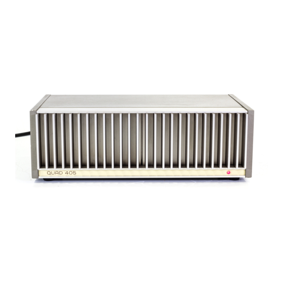
Table of Contents
Advertisement
Quick Links
- 1 Amplifier Board Layout M12565 Iss
- 2 Circuit Diagram M12333 Iss. 6 - Amplifier Pcb M12565 Iss
- 3 Circuit Diagram M12333 Iss. 7 - Amplifier Pcb M12565 Iss
- 4 Circuit Diagram M12333 Iss. 10 - Amplifier Pcb M12565 Iss
- 5 Modifications
- 6 Circuit Diagram M12333 Iss. 5 - Amplifier Pcb M12368 Iss. 9
- 7 Conversion of a 405 to a Mono 180 Watt Amplifier
- 8 Replacing Transformer
- Download this manual
Advertisement
Table of Contents

Summary of Contents for Quad Electroacoustics QUAD 405
- Page 1 Œ 405 POWER AMPLIFIER Service Data The Acoustical Manufacturing Co. Ltd. (Œ) Huntingdon, Cambridgeshire, PE29 6XU, England Tel: +44(0)1480 447700 Fax: +44(0)1480 431767 www.quad-hifi.co.uk...
-
Page 2: Table Of Contents
page Contents Circuit Description Test Equipment Disconnecting Clamp Circuits Amplifier Circuit Testing Clamp Circuit Testing Fault Finding Modifications Clamp Circuit Replacing a Clamp Board Conversion of a 405 to a Mono 180 watt amplifier Replacing Transformer Replacing Amplifier Modules Π405-2 Assembly Diagram Circuit Diagram M12333 iss. -
Page 3: Circuit Description
CIRCUIT DESCRIPTION The QUAD 405 is ã two channel power amplifier primarily intended for use in high quality sound reproducing systems. The amplifier is usually used with QUAD control units though other signal sources can readily be accommodated. Û amplifier uses â current dumping output circuit, á Œ invention which eliminates many of Á problems associated with transistor amplifiers, and covered by patents in several countries. -
Page 4: Test Equipment
0 to 12V d.c. power supply Variac a.c. power supply Fig. 2 illustrates a simple switching circuit which may assist if much testing is anticipated. SUGGESTED SWITCHING ARRANGEMENT FOR TESTING QUAD 405 Fig. 2 Before testing, Á cover of Á 405 should be removed. -
Page 5: Amplifier Circuit Testing
AMPLIFIER CIRCUIT TESTING M12368 - M12565 Á following test procedure is with reference to a 240V amplifier with no voltage limiters. Select: Controls Y1 - 0.5V/cm d.c. coupled Y2 - 0.1V/cm d.c. coupled Timebasë 0.2 ms/cm ST 17OOA- Volts/power 100W RMS Distortion Ratio 0.01% 8OkHz and 400Ï... -
Page 6: Fault Finding
FAULT FINDING The following information may assist in locating faults occuring on the amplifier boards of a 405. In each case only the faulty channel of the 405 is driven, as in the test procedure. The input should be a sine wave of 0.5V RMS and the output should be applied to an 8„ load unless otherwise stated. The numbers refer to the relavent test check. -
Page 8: Modifications
MODIFICATIONS TO PRINTED CIRCUIT BOARDS. Amplifier Board M12368 iss.5 originally fitted. Circuit diagram iss. 2. Amplifier board M12368 iss.6 Copper track layout modified - component layout ünchanged. Amplifier board M12368 iss.7 Circuit diagram iss. 3. R4 changed from 10k to 22k R5 changed from 10k to 4k7 R9 changed from 180„... -
Page 9: Clamp Circuit
CLAMP CIRCUIT Introduced co-incident with amplifier PCB M12368 iss. 9 ¤ serial number 9001. All 405s with serial numbers 9000 ¶ under being returned for service, should be fitted with å clamp board as shown below. At serial number 59001 Á clamp circuit was fitted as an integral part of the amplifier board M12565 iss. 3. Û... -
Page 10: Conversion Of A 405 To A Mono 180 Watt Amplifier
CONVERSION OF 405 TO A MONO 180W AMPLIFIER To carry out Á conversion, t˙e modification kit œ410MOD should first be obtained. Remove thë 405 cover ¶ base plate. Unplug thé AMP connectors from Á right-hand channel PCB (right-hand side when viewed from front). Release the clip securing thë... -
Page 11: Replacing Transformer
™ ™ Fig. 16 REPLACING THE QUAD 405 TRANSFORMER Disconnect the a.c. supply and remove top cover (2 M4 screws) and bottom plate (4 M4 screws). Note the connections ¶ then unsolder the external wiring to the a.c. supply transformer. - Page 12 Œ 405-2 Û original 405 provided 100 Watts per channel into load impedances between 4.5„ and 8 „. To meet Á need of 4„ and 8„ loudspeakers whose impedance falls below 4.5„, Á 405-2 was introduced in January 1983 at serial number 65000, but thê 405 modules had already been fitted from serial number 62500 onwards. Many earlier amplifers have also since been converted to 405-2 by owners ¶...


Need help?
Do you have a question about the QUAD 405 and is the answer not in the manual?
Questions and answers