Advertisement
Quick Links
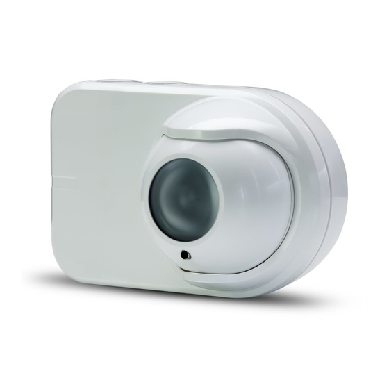
Installation Sheet - OSID Smoke Detection System
This installation sheet provides information on how to install the OSID Smoke Detection System. Full product
information can be found in the Product Guide (Document No. 15204).
OSID Alignment Tools for the Emitter and Imager are sold separately. They are required for all product installations.
Please contact your local Xtralis supplier for ordering information.
OSID Installation Kit (OSID-INST)
1
Determine the positions of the Imager and Emitter Components.
Make sure that the intended mounting locations meet the following criteria:
•
Emitter spacing must comply with local codes and standards (B)
•
Emitters must be located within the Field of View (FOV) of the Imager (A)
•
Clear path between the Emitter and Imager
•
Mounted well above the head-height of a person
•
Avoid direct sunlight onto the units
When securing the detector to the mounting surface, mount the Imager first so that the approximate edges of its
field of view can be determined. This will show the region in which the Emitter units can be located.
The Imager and Emitter/s should be placed within a distance H below the ceiling. This value will vary according
to regional specifications, geometry, and specific requirements for the installation. The distance H for flat
ceilings is shown in the following table.
Basic spacing requirements for "S" in diagram (B) are shown in the following table.
For full information on spacing requirements, please refer to your local codes and standards.
2
Detach Mounting Bracket and Front Cover.
•
To Detach the unit from the Mounting Bracket (A), open the front cover and with a screwdriver push the
lip backwards to then slide the unit up to detach from the Mounting Bracket
•
To provide cable access to the Termination Card of the Imager or externally-powered Emitter, use a
screw driver as shown in (B) to remove the Front Cover (C) from the main assembly. Remove the cut-
outs from the back or top of the main assembly by using a sharp blade to cut around the circular discs.
3
Mounting via Mounting Bracket (Option 1):
Please follow the instructions in this step if you have chosen to secure the detector component to the mounting
surface using the supplied mounting bracket. If mounting directly to the mounting surface, please skip to Step 4.
•
Using the screw holes of the bracket as a template, mark the installation point (A).
•
Use the appropriate fasteners to fix the mounting brackets to the mounting surface. It is recommended
that starwashers are used to prevent the brackets slipping.
•
Attach the rear assembly of the component onto the mounting brackets (B)
•
When mounting the Imager units onto the brackets, ensure that the ribbon cable at the back of the front
ball does not get caught between the unit and the bracket, as movement of the front ball may pull the
ribbon cable out of the connectors.
4
Mounting directly to the mounting surface (Option 2):
Follow this step if you have chosen to secure the detector component directly onto the mounting surface without
using the supplied mounting bracket.
•
Drill the mounting screw holes of the detector component (three places) (A).
•
Using the drilled screw holes as a template, mark the installation point.
•
Use appropriate fasteners to secure the detector component to the mounting surface.
Standard
Distance from Ceiling (H)
NFPA72
-
AS1670.1
25 to 600 mm (1 to 23.6 in.)
BS5839.1
25 to 600 mm (1 to 23.6 in.)
GB50166
300 to 1000 mm (11.8 to 39.4 in.)
Standard
Maximum Spacing
NFPA72
18.3 m (60 ft)
AS1670.1
14 m (45.9 ft)
BS5839.1
15 m (49.2 ft)
GB50166
14 m (45.9 ft)
A
Y
X
Y
X = HORIZONTAL FOV
Y = VERTICAL FOV
B
X°
A
B
C
A
B
A
B
Advertisement

Related Manuals for Xtralis OSID


Summary of Contents for Xtralis OSID
- Page 1 Installation Sheet - OSID Smoke Detection System This installation sheet provides information on how to install the OSID Smoke Detection System. Full product information can be found in the Product Guide (Document No. 15204). OSID Alignment Tools for the Emitter and Imager are sold separately. They are required for all product installations. Please contact your local Xtralis supplier for ordering information. OSID Installation Kit (OSID-INST) Determine the positions of the Imager and Emitter Components. Make sure that the intended mounting locations meet the following criteria: • Emitter spacing must comply with local codes and standards (B) • Emitters must be located within the Field of View (FOV) of the Imager (A) • Clear path between the Emitter and Imager • Mounted well above the head-height of a person • Avoid direct sunlight onto the units When securing the detector to the mounting surface, mount the Imager first so that the approximate edges of its field of view can be determined. This will show the region in which the Emitter units can be located. The Imager and Emitter/s should be placed within a distance H below the ceiling. This value will vary according to regional specifications, geometry, and specific requirements for the installation. The distance H for flat ceilings is shown in the following table. X = HORIZONTAL FOV...
- Page 2 NEXT Vout PREV DETECTOR EXTERNAL RESET CONTROL PANEL 5 - 32 VDC ≥ 3 SECONDS Manually adjust the Emitter/s and Imager until they are aligned: Note: The OSID Laser Alignment Tool must be used to align the system. Follow these steps to adjust the optical sphere (A) of the detector component to align the system: 1. Switch on and insert the OSID Alignment Tool in the alignment hole (B). 2. To align an Emitter, move the alignment tool until the laser beam points near the Imager and within the limits shown in Diagram C. Rotate the alignment tool 90° clockwise to lock the sphere into place and activate the Emitter. A STOP position will be felt when the sphere is locked. 3. To align the Imager, use the OSID Alignment Tool to position the Imager to point directly towards a single Emitter or in the gravitational centre of multiple Emitters. Rotate the alignment tool 90° clockwise to lock the sphere into place. A STOP position will be felt when the sphere is locked. 4. Make sure that the alignment of the Emitter or Imager is according to the specified limits after locking the sphere. Remove the laser tool.
Need help?
Do you have a question about the OSID and is the answer not in the manual?
Questions and answers