Advertisement
Quick Links
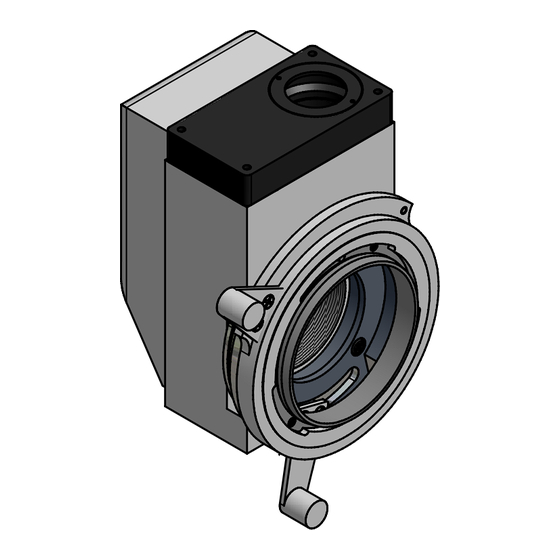
BEFORE UPGRADE
(COMPLETE ORIGINAL
B
CAMERA COUPLER ASSEMBLY)
A
Mounting bayonet for
original Topcon film camera
(Topcon camera model AM-SL, etc.)
2
Topcon SL-5d (6e) Slit Lamp
Digital Camera Upgrade
Product Illustration
Richard J Kinch, PhD -- Palm Beach County, Florida USA -- http://www.truetex.com
2
1
(COMPLETE DIGITAL
CAMERA COUPLER ASSEMBLY)
topcon_sl-5d,6e-Tmount.idw
1
AFTER UPGRADE
Mounting bayonet for
digital SLR camera
(Canon, Nkon, etc.)
B
A
Advertisement

Related Manuals for Topcon SL-5d

Summary of Contents for Topcon SL-5d
- Page 1 Topcon SL-5d (6e) Slit Lamp Digital Camera Upgrade Product Illustration AFTER UPGRADE BEFORE UPGRADE (COMPLETE DIGITAL (COMPLETE ORIGINAL CAMERA COUPLER ASSEMBLY) CAMERA COUPLER ASSEMBLY) Mounting bayonet for Mounting bayonet for digital SLR camera original Topcon film camera (Canon, Nkon, etc.) (Topcon camera model AM-SL, etc.)
- Page 2 This coupler block is a component of the as Nikon) are available. original slit lamp instrument and not supplied with this kit. While all Topcon SL-5d and SL-6e slit lamps are ready to accept this coupler, not all of them were equipped with this removable, optional item.
- Page 3 CAUTION: The original Topcon screws are extremely tight and glued in place with a threadlocker compound. Removing these screws without damage requires proper tools and a firm hand. Topcon SL-5d (6e) Slit Lamp If you have any doubt or difficulty in performing this disassembly, Digital Camera Upgrade we recommend you send your components to us for installation.
- Page 4 STEP 2: On the back of the old camera mount assembly, remove the stud, using a flat-bladed screwdriver. Again, use care and firm pressure, because the parts should be thread-locked. Breech ring with handle STEP 3: After removing the stud, separate the breech ring and its handle from the rest of the assembly by unscrewing it *clockwise* (the threads are LEFT HANDED, reversed from the usual direction).
- Page 5 4 screws Threaded ring STEP 4: Remove the 4 screws holding the threaded ring on the rest of the assembly. Separate the threaded ring from the rest of the assembly. Rest of the assembly Richard J Kinch, PhD -- Palm Beach County, Florida USA -- http://www.truetex.com topcon_sl-5d,6e-Tmount.idw...
- Page 6 Two screws to remove STEP 5: From remaining assembly, remove two screws holding handle onto lock ring, and separate the handle and the lock ring from the base ring. Handle to separate Use care as these screws should be thread-locked. This completes the disassembly.
- Page 7 Screws and handle previously removed from lockring STEP 6: Assemble the old lockring onto the back of the new T-mount ring. This is a close, nesting fit, so use care when assembling. The two posts on the lockring where the New T-mount ring handle attaches must fit into the curved slot in the T-mount ring.
- Page 8 STEP 7: Assemble the T-mount assembly to the coupler block Original coupler block with the 4 screws previously removed. Screw the T-mount camera adapter onto the threads of the T-mount assembly. These threads are ordinary right-hand threads that screw on clockwise. The threads are fragile, Standard T-mount so use care.
Need help?
Do you have a question about the SL-5d and is the answer not in the manual?
Questions and answers