
Related Manuals for Delphi EZ-Pro 15-6 Kiln

Summary of Contents for Delphi EZ-Pro 15-6 Kiln
- Page 1 EZ-Pro 15-6 Kiln Operating Manual Delphi has teamed up with Jen-Ken Kilns and Orton to produce the most user friendly, versatile kiln for glass artists ever. www.DelphiGlass.com 800-248-2048 3380 E. Jolly Road Lansing, MI 48910...
- Page 2 This manual contains instructions on the operation of the kiln and Delphi EZ-PRO controller as well as a discussion of general fusing procedures. It is not intended to replace a fusing class or comprehensive fusing instructional media. Revised: October 22, 2007...
-
Page 3: Table Of Contents
Table of Contents Safety First ....................5 About Your Kiln ..................6 Introduction ..................6 Kiln Accessories ................8 Kiln Specifications ................9 Choosing a Location for Your Kiln ..........10 Setting up Your Kiln ..............11 Quick Start Guide or Enough Reading –... - Page 4 Firing Process ..............31 Firing Stages ..............32 Firing 90 COE Glass for Beginners ..........34 Firing 96 COE Glass for Beginners ..........36 Batch Annealing Glass Beads ............38 Firing Your Metal Clay Projects ............. 40 Intermediate Mode ................ 42 Keeping a log ..............
-
Page 5: Safety First
Do not drop or slam the lid shut. o Let the kiln cool to room temperature before opening the lid. o NOTE: If you are in doubt about anything, call Delphi Glass 800.248.2048 or Jen-Ken Kilns during regular business hours at 800.329.KILN. -
Page 6: About Your Kiln
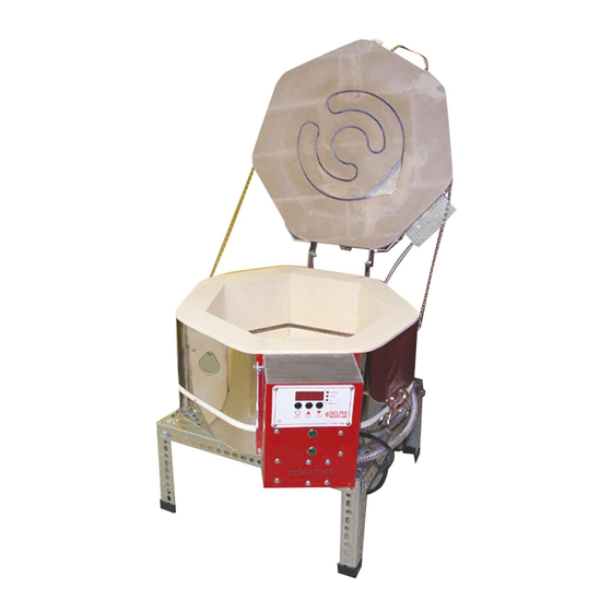
Introduction The Delphi EZ- Pro Kiln 15-6 is a professional quality Jen-Ken kiln. The controller has been designed and programmed to Delphi specifications by Orton Ceramics. Elements Elements are the coils of wire that produce heat inside the kiln. They are made from a high quality, high-temperature wire. - Page 7 Kiln Brick All Jen-Ken kilns are made of hand selected 2400°F refractory brick. The brick is strong as a whole and has a very long life. The brick can chip easily and care should be taken to avoid bumps while loading and unloading shelves.
-
Page 8: Kiln Accessories
RECOMMENDED KILN ACCESSORIES Glass Kiln Wash is a mixture of very fine minerals that will not fuse or melt together at high temperatures and act as a barrier between the kiln shelf or mold and glass. It is used to prevent glass from sticking to the firebrick bottom of the kiln and the kiln shelves. -
Page 9: Kiln Specifications
KILN SPECIFICATIONS To operate the kiln safely and efficiently, your kiln needs the proper electrical outlet with the correct electrical capacity and voltage. The chart below will assist you in the selection of the proper wire and breaker size for your Jen-Ken Kiln. A licensed electrician or the local power company should determine if you have the proper voltage and wiring. -
Page 10: Choosing A Location For Your Kiln
CHOOSING A LOCATION FOR YOUR KILN The proper location is as important as choosing the right kiln. Below are some safety guidelines. o Please review the safety considerations listed on page 5 when selecting a location for your kiln. o Your kiln should be located in a covered, dry, fireproof and well ventilated area, but never in a small enclosed area such as a closet, cabinet or very small room. -
Page 11: Setting Up Your Kiln
SETTING UP YOUR KILN o Assemble the kiln stand and place it on the floor in your work space. o Remove all packaging from the kiln and place it on the stand. Do not plug it in yet. o Make sure that your kiln sits completely level. It may be necessary to use a level to determine o Open the lid of the kiln and inspect the interior looking for anything unusual like broken brick. -
Page 12: Enough Reading - I Want To Melt Something
Enough of this reading stuff – I want to melt something! For those of you who can‟t wait, here is a brief guide to get you up and running. It is strongly recommended that you do take time to look over the controller instructions as soon a possible. -
Page 13: Ez-Pro Controller
Delphi EZ-Pro Controller This button is for selecting a firing program and advancing through the programming steps. After programming is complete, use this button to Start and Stop the firing. This button is used to change the firing program during programming and to change the display values for specific program settings. -
Page 14: Temperature Display Preference
diagnostic alarms that may occur during a firing. To silence an active buzzer, Press any button. Temperature display preference All temperature displays on the controller can be viewed as F (Fahrenheit) or C (Celsius). The temperature display preference is set by positioning a small circuit board jumper on the back side of the controller that is labeled C/F. - Page 15 Ramp Rate Each step of a firing program must have a programmed Rate of temperature increase or decrease. These rate values are selected as Degrees per Hour. During the programming the display prompt for Rate settings are rA followed by the step number like rA1, rA2, rA3, etc…...
-
Page 16: Program Modes
Program Modes The EZ-Pro controller allows the operator to select 1 of 5 program modes for different glass art or craft applications. The program mode is prompted on the controller display when the controller is turned on. The 5 available modes are -90- For 90 COE glass projects -96-... -
Page 17: Coe Program Mode
-90- Program Mode The 90 COE mode provides 4 preset firing schedules for glass forming and 4 optional User Programs for creating custom firing schedules. The 4 preset programs are recommended firing schedules that can also be customized if necessary. These programs provide the various heating and cooling steps for easy selection. -
Page 18: Coe Program Mode
The preset 90 COE programs can be edited. Each program segment can be changed by the operator. To restore the factory values, enter a zero value for the first rA1 segment of each program and press the Program button. In addition to the 90 COE preset programs, the -90- mode provides 4 User defined programs for custom firing schedules. -
Page 19: Bead Program Mode
This program heats at 300F/hour to 1165F and holds this temperature for 10 minutes. Then cools rapidly to 960F and holds this temperature for 60 minutes. Then cools at 100F/hour to 800F and shuts off. Program Rate Temp Hold FUSE 300F/hour 1220F 00.30... -
Page 20: Metal Clay Program Mode
This program heats at 400F/hour to 980F and holds this temperature for 10 minutes. Then cools at 150F/hour to 670F and shuts off. 2” beads batch annealing Displayed as bd 3 This program heats at 300F/hour to 980F and holds this temperature for 20 minutes. Then cools at 100F/hour to 670F and shuts off. -
Page 21: User Program Mode
This program heats as fast as possible to 1650°F and holds this temperature for 10 minutes. PMC+ Slow Displayed as P-SL This program heats at 1500°F/hour to 1470°F and holds this temperature for 30 minutes. PMC3 Slow Displayed as P3SL This program heats at 1500°F/hour to 1110°Fand holds this temperature for 45 minutes. - Page 22 Each step of a firing program must have a programmed Rate of temperature increase or decrease. This is the speed of the heat-up or cool-down. These rate values are selected as Degrees per Hour. „Degrees per hour‟ rate can be determined by dividing the total amount of temperature change by the number of hours required to achieve the temperature change.
-
Page 23: Other Program Notes
Hold Time is entered in Hours & Minutes format. The middle decimal point light on the controller display is used to separate Hours from Minutes. For Example, a 1 hour hold time should be set like [01.00], while a 1 hour and 30 minute hold time would be [01.30]. -
Page 24: Thermocouple Offset Option
Thermocouple Offset Option Thermocouple Offset allows you to correct the temperature display a few degrees in a positive or negative direction. This can improve the controller accuracy if the thermocouple probe is aged or if the firing results appear to be slightly under or over fired. -
Page 25: Options Menu
Options Menu During an active firing, the Increase button will activate an options menu and scroll through the available options with each button press. These options allow you to make adjustments to the firing program without stopping the firing. The available options follow. -
Page 26: Flow Diagram For Options Menu
To set the alarm, Press Increase button during the active firing until the alarm prompt ALAr is displayed. Then Press the Program button to display the current alarm temperature setting. Adjust the temperature setting with the Increase or Decrease buttons. Then Press Program button to return to the normal firing mode. -
Page 27: Status Display Codes
3. When power is restored, the temperature drop during the power interruption must be less than 72ºF (40ºC). If not, the display will show the alarm code PF 3 and terminate the firing. Status Display Codes Below is a list of normal display codes which indicate the controller mode of operation. - Page 28 FAIL - This alarm will appear during an active firing and indicates that the thermocouple sensor is no longer detected. The signal was lost during and the firing was terminated. The controller can not operate without a thermocouple signal. In most cases, the thermocouple has failed and will need replacement, or the electrical connections for the thermocouple may be loose or damaged.
-
Page 29: Wiring Diagram
FE # - Fatal software Errors, FE Alarms indicate a hardware failure or software problem with the controller. These alarms will disable the normal controller operation and require corrective action. If a Fatal Error occurs during an active firing, the firing is terminated. These alarms include; FE 1 –... -
Page 30: Beginner Instructions
FUSED GLASS PROJECTS Working with Tested Compatible Glasses To ensure success when fusing glass, use glass that has been pre-tested by the manufacturer How to prepare your glass project Select glass that is “tested compatible” and has the same COE (Coefficient of Expansion) for the entire project. -
Page 31: Firing Process
Between 1000°F and 1250°F (538°C – 677°C), the glass is softening, becoming more pliable, and starting to act more like a liquid and less like a solid. At the top end of this temperature range, glass will slump if held for a period of time. Visually the top layer of the glass will begin to soften and round over on the edges and the sides will start to become wet and glossy looking, or fire polished. -
Page 32: Firing Stages
Firing stages Initial Heating from Room Temperature (room temperature to 1200°F range): During the initial heating, the glass is very brittle and susceptible to breaking (thermal shock) if it‟s heated up too quickly. During this stage, it‟s best to take a conservative approach and slowly heat up the glass. - Page 33 The size of your project is defined by both the diameter of the piece as well as the number of layers of glass. Glass as a material is a very poor heat conductor. The larger or thicker your project is, the more slowly it needs be fired so that the glass has more time to heat or cool evenly all of the way through.
-
Page 34: Firing 90 Coe Glass For Beginners
FIRING YOUR 90 COE GLASS PROJECT Please note: All of the pre-programmed firing schedules are based on the slowest firing schedule for large projects. These programs can be used for all of your glass fusing regardless of project size. Begin in the IDLE mode To begin programming the kiln, it must be in the IdLE mode. - Page 35 Press (Decrease) button to engage the correct firing program and the LED light beside “Review” will light up. Additionally, the firing program will begin to display on the LED display beginning with rA 1. Once the review has been completed, the display will show Strt.
-
Page 36: Firing 96 Coe Glass For Beginners
FIRING YOUR 96 COE GLASS PROJECT Please note: All of the pre-programmed firing schedules are based on the slowest firing schedule for large projects. These programs can be used for all of your glass fusing needs regardless of project size. Begin in the IDLE mode To begin programming the kiln, it must be in the IdLE mode. - Page 37 Press (Decrease) button to select the firing program and once selected the LED light beside “Review” will light up. Additionally, the firing program selected will begin to display on the LED display beginning with rA 1. Once the review has been completed, the display will show Strt.
-
Page 38: Batch Annealing Glass Beads
ANNEALING GLASS BEADS About these annealing programs Programs 1-3 in this grouping will batch anneal glass beads made of Bullseye, System96, and Moretti (Effetre) glasses. Program 4 is set for continuous annealing while you create. Safety First Never try to put a bead already on the mandrel directly into a preheated or actively firing kiln unless the kiln has a properly installed bead door. - Page 39 Once completed the LED display will return to the IdLE mode. Select the firing program To select the correct firing program: Press (Program) button to display the current firing program Press (Increase) button to scroll to the correct program for your project Batch annealing beads up to ½”...
-
Page 40: Firing Your Metal Clay Projects
FIRING METAL CLAY Drying Time Allow your pieces to be completely dried before firing them in the kiln to ensure that they don‟t warp. Loading the kiln If you fire both glass and metal clay in your kiln, it is recommended that you invest in a second shelf so that you can fire only glass on the glass kiln shelf, and only metal clay silver on the other kiln shelf. - Page 41 To select the correct firing configuration: Press (Increase) button to scroll to the correct configuration, Metal Clay Press (Program) button to select this configuration. Once completed the LED display will return to the IdLE mode. Select firing program To select the correct firing program, Press (Program) button to display the current firing program Press (Increase) button to scroll to the correct program for your project P-FS Fast Fire PMC+...
-
Page 42: Intermediate Mode
INTERMEDIATE MODE: Keeping a log There is no “one program fits all” firing schedule for kilns. Even supposedly identical kilns behave slightly differently. Plugging the same kiln into different outlets in your house may also alter the firing schedule you need. Additionally, different size projects or different colors of glass will react differently, necessitating changes to your firing schedules. -
Page 43: Professional Mode
PROFESSIONAL MODE: PROGRAMMING CUSTOM FIRING PROGRAMS You can enter up to 22 custom firing programs in the controller for all of your firing needs. Each program can contain up to 8 steps (segments). Special note: All changes made to both the pre-programmed and customer programs will be permanently be stored in the memory until you change them! Pre- Custom... - Page 44 11. If you are programming over an existing program that has more segments than the current program you are entering, at the beginning of the next segment, Press (Decrease) button to change the rate to 0 12. Press (Program) button to program the change, and the display will prompt Strt. 13.
- Page 45 90 COE Pre-Programmed Firing Programs FUSE Segment Rate, °/Hr Set Point Temp Hold/Soak Time Full Fuse 300° F 1250° F 30 min 600° F 1480° F 10 min Full 960° F 40 min 150° F 700° F Segment Rate, °/Hr Set Point Temp Hold/Soak Time Tack Fuse 300°...
- Page 46 90 COE Custom Firing Programs Rate, Set Point Hold/Soak USr1 Segment °/Hr Temp Time Rate, Set Point Hold/Soak USr2 Segment °/Hr Temp Time Rate, Set Point Hold/Soak USr3 Segment °/Hr Temp Time Rate, Set Point Hold/Soak USr4 Segment °/Hr Temp Time...
- Page 47 96 COE Pre-Programmed Firing Programs Rate, Set Point Hold/Soak FUSE Segment °/Hr Temp Time Full Fuse 300° F 1220° F 30 min 600° F 1465° F 10 min Full 960° F 40 min 100° F 800° F Rate, Set Point Hold/Soak Segment °/Hr...
- Page 48 96 COE Pre-Programmed Firing Programs Rate, Set Point Hold/Soak USr1 Segment °/Hr Temp Time Rate, Set Point Hold/Soak USr2 Segment °/Hr Temp Time Rate, Set Point Hold/Soak USr3 Segment °/Hr Temp Time Rate, Set Point Hold/Soak USr4 Segment °/Hr Temp Time...
- Page 49 Bead Annealing Pre-Programmed Firing Programs Segment Rate, °/Hr Set Point Temp Hold/Soak Time Small Beads (1/2") 500° F 980° F 5 min 300° F 670° F Segment Rate, °/Hr Set Point Temp Hold/Soak Time Medium Beads (1") 400° F 980° F 10 min 150°...
- Page 50 Bead Annealing Custom Firing Programs Rate, Set Point Hold/Soak USr1 Segment °/Hr Temp Time Rate, Set Point Hold/Soak USr2 Segment °/Hr Temp Time Rate, Set Point Hold/Soak USr3 Segment °/Hr Temp Time Rate, Set Point Hold/Soak USr4 Segment °/Hr Temp Time...
- Page 51 PMC Pre-Programmed Firing Programs Rate, Set Point P-FS Segment °/Hr Temp Hold/Soak Time PMC + Fast Full 1650° F 10 min Rate, Set Point P-SL Segment °/Hr Temp Hold/Soak Time PMC + Slow 1500° F 1470° F 30 min Rate, Set Point P3SL Segment...
- Page 52 Metal Clay Custom Firing Programs Rate, Set Point Hold/Soak USr1 Segment °/Hr Temp Time Rate, Set Point Hold/Soak USr2 Segment °/Hr Temp Time Rate, Set Point Hold/Soak USr3 Segment °/Hr Temp Time Rate, Set Point Hold/Soak USr4 Segment °/Hr Temp Time...
- Page 53 User Custom Firing Programs (USr) USr1 Segment Rate, Set Point Temp Hold/Soak Time °/Hr USr2 Segment Rate, Set Point Temp Hold/Soak Time °/Hr USr3 Segment Rate, Set Point Temp Hold/Soak Time °/Hr USr4 Segment Rate, Set Point Temp Hold/Soak Time °/Hr...
- Page 54 USr5 Segment Rate, Set Point Temp Hold/Soak Time °/Hr USr6 Segment Rate, Set Point Temp Hold/Soak Time °/Hr...
-
Page 55: Controller Warranty
Orton Controller Limited Warranty This limited warranty is given only to the immediate purchaser (“Buyer”) of the Autofire ® Express kiln controller. This limited warranty is not transferable. The Edward Orton Jr. Ceramic Foundation (“Orton”) warrants the controller motherboard installed on the Express (“Warranted Components”) to be in good working order under normal operating conditions for a period of one (1) ®...
Need help?
Do you have a question about the EZ-Pro 15-6 Kiln and is the answer not in the manual?
Questions and answers
"Menu" not engaging on EZ-Pro Kiln Controller
The "Menu" may not be engaging on the Delphi EZ-Pro 15-6 Kiln Controller because the controller is not in the correct state to accept input. Ensure the kiln is plugged in, turned on, and displaying "IdLE" before attempting to access the menu. Additionally, check if the correct button sequence is being followed to enter the menu. If the issue persists, there may be a problem with the controller or a failed relay.
This answer is automatically generated