Table of Contents
Advertisement
Quick Links
OPERATING AND
INSTALLATION MANUAL
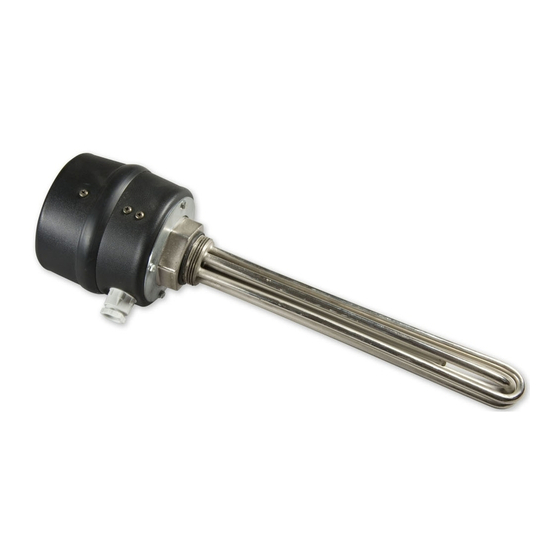
SCREW-MOUNTED ELECTRICAL HEATING
Družstevní závody Dražice - strojírna s.r.o.
Dražice 69, 294 71 Benátky nad Jizerou
Phone.: +420 /326 370 990
Fax: +420 / 326 370 980
e-mail: prodej@dzd.cz
UNIT
TJ 6/4" -2
TJ 6/4" - 2,5
TJ 6/4" - 3.3
TJ 6/4" - 3.75
TJ 6/4" - 4.5
TJ 6/4" - 6
TJ 6/4" - 7.5
TJ 6/4" - 9
Advertisement
Table of Contents

Related Manuals for Drazice TJ 6/4“ -2


Summary of Contents for Drazice TJ 6/4“ -2
- Page 1 OPERATING AND INSTALLATION MANUAL SCREW-MOUNTED ELECTRICAL HEATING UNIT TJ 6/4“ -2 TJ 6/4“ - 2,5 TJ 6/4“ - 3.3 TJ 6/4“ - 3.75 TJ 6/4“ - 4.5 TJ 6/4“ - 6 TJ 6/4“ - 7.5 TJ 6/4“ - 9 Družstevní závody Dražice - strojírna s.r.o. Dražice 69, 294 71 Benátky nad Jizerou Phone.: +420 /326 370 990 Fax: +420 / 326 370 980...
-
Page 2: Table Of Contents
CONTENTS PRODUCT TECHNICAL SPECIFICATION ....................... 4 FUNCTION DESCRIPTION ........................4 ADVICE FOR CUSTOMERS ........................4 DESIGN AND GENERAL HEATER DIMENSIONS ................... 4 OPERATION AND FITTING INSTRUCTIONS ....................5 ASSEMBLY ............................5 ELECTRICAL INSTALLATION ........................ 6 2.2.1 GENERAL INFORMATION for ELECTRICAL INSTALLATION ............6 2.2.2 WIRING SCHEME ........................ - Page 3 CAREFULLY READ THIS MANUAL BEFORE INSTALLING THE WATER HEATER! Dear customer, The Works Cooperative of Dražice – Machine Plant, Ltd., would like to thank you for your decision to use a product of our brand. With this guide, we will introduce you to the use, construction, maintenance and other information on electrical water heaters.
-
Page 4: Product Technical Specification
1 PRODUCT TECHNICAL SPECIFICATION 1.1 FUNCTION DESCRIPTION The screw-mounted electrical heating unit (heating unit) is designed exclusively for water heating. It is designed as an additional heating source in water heaters connected in a system with solar collectors. It can also be used as an additional source of heating in accumulation tanks. -
Page 5: Operation And Fitting Instructions
HEATING HEATING TIME TIME FROM FROM ELECTR. UNIT UNIT OUTPU CONNECTION 10°C TO TYPE 35°C TO PROTECTI TEMPERAT LENGTH LENGTH WEIGHT connection 60°C 60°C URE SCOPE (L1) (approx 150 (approx 150 l) °C 1 PE-N AC TJ 6/4“ – 2 IP 45 5 –... -
Page 6: Electrical Installation
2.2 ELECTRICAL INSTALLATION 2.2.1 GENERAL INFORMATION FOR ELECTRICAL INSTALLATION The heating unit is connected to a 230/400 V 50 Hz electrical network conductor with a corresponding section and a protection adequate to the heating element output. Notice: The power supply must contain a breaker disconnecting all poles of the network. Perform the installation in compliance with applicable CSN standards. -
Page 7: Heating Unit Operation
2.3 HEATING UNIT OPERATION Simple control consists only of setting the desired temperature on the control thermostat knob. The setting range is 5 -74°C. The recommended set temperature is 60°C approximately. The * symbol – fuse against freezing 5-8°C. When the control light is on, the element is running. 2.4 INSPECTION, MAINTENANCE Maintenance involves decalcification of the heating element in certain time intervals selected by water hardness at the place of use. -
Page 8: Important Notices
3 IMPORTANT NOTICES 3.1 INSTALLATION REGULATIONS When active, the element and the termowells have to be surrounded with a sufficient amount of water from all sides. Thermic water flow must not be prevented. Mounting positions – horizontal or vertical from under. The length of the 6/4 “...
Need help?
Do you have a question about the TJ 6/4“ -2 and is the answer not in the manual?
Questions and answers