Table of Contents
Advertisement
Quick Links
Dear Customer,
You have just purchased a ROLLAND Spreader.
We appreciate the trust you place in us.
The Spreaders by ROLLAND were designed to make the most of
spreading techniques. They result from our technology and our
experience in this field.
This manual should be considered as part of your Rolltwin or
Rollmax Spreader.
For proper use, and to exploit all the capabilities of your Spreader,
we recommend that you carefully read and follow all instructions in
this manual.
The proper function and longevity of your spreader depends on
it as well as your safety and that of others.
Keep this instruction manual so that you can consult it in due
course. It must always accompany the spreader, even in case of
resale.
Non-compliance with the said instructions indemnifies the
manufacturer and the dealer of all liability.
We reserve the right to make any changes to our products at
any time we deem useful without obligation to modify products
previously delivered or on order. We also reserve the right to change
without notice models that are defined in our catalogues, brochures
or on our website.
Yours faithfully.
Original instruction : French
03/2012
Z.A des Landes
29800 TREFLEVENEZ - FRANCE
Tél. : 00 33 (0)2 98 85 13 40
Fax : 00 33 (0)2 98 21 38 15
www.remorquerolland.com
1
V –h –
NT0002
Advertisement
Table of Contents

Related Manuals for ROLLAND ROLLTWIN

Summary of Contents for ROLLAND ROLLTWIN
- Page 1 The Spreaders by ROLLAND were designed to make the most of spreading techniques. They result from our technology and our experience in this field. This manual should be considered as part of your Rolltwin or Rollmax Spreader. For proper use, and to exploit all the capabilities of your Spreader, we recommend that you carefully read and follow all instructions in this manual.
-
Page 2: Table Of Contents
Summary 1-Safety instructions 2-Conditions of warranty 3-Presentation of the vehicle -Areas of use -Vehicle identification -Technology and options 4-Commissioning (PDI) 5-Normal use and instructions -parking -loading -transport -spreading 6-Settings -Drawbar 7-Care and maintenance -Braking systems -undercarriage -Cleaning/lubrication -Adjusting the bed tension -Adjusting the steering axle -Maintenance of controller and hydraulic unit - Wearing parts... -
Page 3: 1-Safety Instructions
1-Safety instructions Before commissioning, study the instructions and follow the safety guidelines! In this user guide we have marked with this symbol all hazards or risks that operators are subject or exposed to. Signs and security stickers attached to the spreader show you that it is safe to use the machine: Respecting the instructions = safety Normal use The spreader is designed and manufactured for normal use as described in this... -
Page 4: 2-Conditions Of Warranty
Spreaders lifts are covered against defects in parts and workmanship for one year from the date of commissioning. In no event can ROLLAND SA be held responsible for an incident due to a failure to comply with instructions for use, safety or maintenance. -
Page 5: 3-Presentation Of The Vehicle
3 – Presentation of the vehicle This manual is common to all spreaders in the ROLLAND range. It was designed to give you all necessary information about the vehicle you have just purchased and to allow you to get the get the most out of it. - Page 6 Drawn agricultural vehicles fall under two distinct regulations : The highway code The labour code Rolland vehicles come with a sheet crossed out with a red bar and a notice containing a statement of compliance. These two documents show that the two regulations have been met.
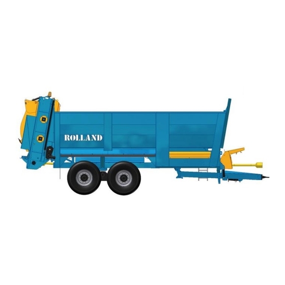
- Page 7 Side view ROLLTWIN ROLLMAX ROLLMA Front and rear view ROLLTWIN ROLLMAX Body Running gear Front panel Beaters Protection cover Slurry door Hose arrier Spreader frame (2100Kg maxi) Drawbar Spreader table Drawbar adjustment V –h – 03/2012 Original instruction : French...
-
Page 8: Technology And Options
Technology and options available : Rings : Welded rotating ring Welded flat ring Removable ring Drawbars with 8 holes interface allowing several types of ring to be fitted (flat, rotating, spoon, DIN) Hydraulic drawbar only on "ROLLMAX" V –h – 03/2012 Original instruction : French NT0002... - Page 9 Driving direction Running gear : Single axle Bogey Rocker with offset shaft Tandem with tie rods Tridem Rollfast V –h – 03/2012 Original instruction : French NT0002...
- Page 10 Bed control: There are several types of floor controls, in each, several functions can be managed from the electrical control box in the cabin in addition to the tractor control valve that is always available. Here in this table are the various available combinations: Wiring diagram for tractor troubleshooting (independent hydraulics).
- Page 11 This table explains the function of the components that make up the 18 existing types of feeds. In the column "relevant system" there are numbers that use the line advances (for example a two section distributor is used in the feeds 121, 122, 123, 221, 222, 223).
- Page 12 Element Function Relevant system Hydraulic motor Supplied with oil, drives the gear which drives bed. motor 160 cm ³ for the All models single drives and two motors cm³ connected in parallel for the double drives. Proportional controller Ensures the distribution of oil in the circuit in proportion to a given electrical...
- Page 13 The various control boxes Element Function Relevant feed Controls the bed and regulates its speed, two setting ranges (hare / tortoise) for optimum accuracy. The driving is done 111, 211 via the tractor control valve Controls the bed and regulates its speed, two setting ranges (hare / turtle) for optimum accuracy.
- Page 14 It requires the installation of a clevis on the tractor. Note that the self-steering Rolland axle can become a follower axle when a tractor is without a clevis because locking cylinders of the follower axle have been retained.
- Page 15 Weighing : It is possible to equip the ROLLTWIN and ROLLMAX spreaders with a weighing system. Weight information is detected by sensors on the drawbar and the axle. The data is then memorised in the weight conrol box per client or plot.
-
Page 16: 4-Commissioning (Pdi)
4 – Commissioning (PDI) Vehicle coupling system : The coupling may not exceed the speed of 32 km/h or 20 mph road speed. The connection is provided by a standard ring (all types of couplings can be used with hook, ring bolt or spoon coupling). PROCEDURE . - Page 17 Connecting the pressure outlets : . The connections must be made with the engine shutdown, hydraulic pressure released and ignition key removed Hose marking Function Hose marking Function Bed pressure (DE) Brakes Bed reverse (DE) Close hood (DE) Load transfer (SE) Open hood (DE)
- Page 18 Brake system : The spreaders are equipped with three brake systems, each one assuring a specific function. When parking, use the mechanical hand brake. During the transport it is the hydraulic brake that is used. The third system is a safety device for in case the coupling breaks (a cord between the hand brake and a fixed point on the tractor).
- Page 19 Pneumatic braking system Element Function Illustration Emergency relay valve Ensuring the service brake and (VRU) the automatic braking of the trailer case coupling breakage or pressure drop in the supply line Static corrector Adjusts the brake pressure, that (optional) is the brake force, depending on the load condition of the vehicle.
- Page 20 1 Emergency relay 2 Fixed correcteur 3 Relay valve 4 Brake valve 5 Reservoir 6 Feed 7 Control 8 Pressure 9 Brake cylinders Example of air braking system on 2 axles (40 kmh) Installation of the drive shaft : PROCEDURE .
- Page 21 Depending on your tractor a bridge on your tractor socket may be necessary. If this is the case: Rolland cannot take any responsibilty for an overheated circuit. This modification is done by the client and is his responsibilty.
- Page 22 Depending on your trailer, one or two clevis forks must be mounted on your tractor. These are provided but the adaptation and installation are not covered by ROLLAND. In fact, depending on the make and model of tractor, the forks' position may vary slightly.
- Page 23 Actuator of the rear axle Axis of the drawbar ring Actuator of the front axle Installing the cylinder : For this operation, no pressure may be present in the circuit. If your installation has only one cylinder, the automatic latching system allows its installation easily. Simply attach the cylinder to the tractor and slowly steer it round to lock it.
- Page 24 Concerning follower and self-steering axles Any self-controlled running gear can be used in steering mode. To do this, simply place the cylinder(s) to the side(s) of the drawbar in the space provided for this purpose. The axis ball cylinder - tractor clevis then serves to block the cylinders. The pressure in the circuit must always be released (monitor through the pressure gauges).
-
Page 25: 5-Normal Use And Instructions
5 – Normal use and instructions Above, the explicit representation of icons shown on the vehicles representing the various risks (risk of crash, fall risk, etc..). Parking: During storage of the vehicle the observance of certain rules is mandatory for your safety but also in order to have a vehicle ready for use when needed. - Page 26 Loading : Any damage due to overloading is in no case covered by manufacturer's warranty. .Never exceed the vehicle payload .Check the good load distribution on the vehicle .Check balance load, good stability manoeuverability of the vehicle. . Ensure during loading that no hard substance (stone, pieces of wood, iron, etc.) is loaded into the spreader, it could cause damage.
- Page 27 Set the PTO in motion without accelerating and bring it to normal speed of 1000 rpm. All ROLLAND spreaders are designed to operate in this regime except in exceptional cases (540 rpm). In all cases, the plan to use is specified by a sticker on the hose carrier at the front of the vehicle.
-
Page 28: 6-Settings
6 – Settings Preamble: Unplug the power supply before carrying out any adjustments (see § 1-1 on page 3) Adjustments to the mechanical drawbar : Adjustments to the mechanical drawbar : The setting of the drawbar enables a level body according to the coupling height, giving a greater flexibility and a maximum weight transfer to the rear axle of the tractor. -
Page 29: 7-Care And Maintenance
7 – Care and maintenance To carry out the maintenance under good conditions, the following safety rules must be met : Block the wheels. Engage the mechanical brake. (hand brake) Unload the vehicle. Check the brake system (every 6 months) Parking and emergency brake Verify the correct tension of the parking / emergency brake. - Page 30 If your vehicle is equipped with self-adjusting rods, the operation of lining play compensation manages itself. Check lining wear through the hole provided for this purpose. If the pads are unusable or questionable, contact your local ROLLAND dealer. View port - linings...
- Page 31 Maintenance of the running gear : Maintenance work on the running gear must be performed by qualified and competent staff with the appropriate tools and a specialised workshop approved by the vehicle manufacturer. General inspection For : ½ tandem, tandem rods Check and tighten all the nuts on the axle fixation flanges and the draw rods if present.
- Page 32 Cleaning and lubricating : Clean the body with copious amounts of water after each transport of corrosive or soiled goods. After washing, follow up with a general lubrication (oil spray) and verify the brake functions. For all cleaning and lubrication operations, the machine should be shut down (see §1-1 of page 3) Every 10 hours: -Grease the bed chain drive front and rear...
- Page 33 Instructions for cleaning Caution: this operation requires special precautions in addition to those cited throughout this document (pages 3, 17, 20 and 26 in particular) and in this chapter. Mandatory: Ensure the machine is stopped and the discharge of the device is complete.
- Page 34 Adjustment of the bed tension : This adjustment must be performed every 50 hours of use. It prevents premature wear of components and keeps the chains in position. To carry out the tension adjustment of the 2-chain there are 2 stretchers (A) outside the skip, for the 4-chain, there are the two tensioners (A) and 2 more (B) in the middle.
- Page 35 Steering axle : Checking and adjusting the alignment Immobilise the vehicle, the steering axle well inline, lock cylinders retracted, on a level surface. Measure the distance between the front wheels and the rear follower axle. The same value should be found. If this is not the case, unblock the 2 lock nuts of the coupling rod, and rotate it in order to get the distance at the front to be identical to that at the back.
- Page 36 Maintaining the regulator and hydraulic unit Shutdown the vehicle (see §1-1 of page 3) Check the oil level and tightness of the tank. Remember to change the oil and regulator filter every year. To change the filter, unscrew the protection bowl (red). Clean the inside of the bowl with a cleaning agent (do not use cloth or paper towels), change the filter and then replace the bowl.
- Page 37 Replacing the wearing parts: The spreader assembly contains parts that wear and must be replaced regularly, there is no advised service life for these parts as they wear out faster or slower depending on the type of manure or according to settings made by the operator. Element Quantity (per beater or per disc) Wear arm - disc...
- Page 38 Maintenance of mechanical housings: Shutdown the machine completely (see § 1-1 on page 3) Change the oil in the various mechanical boxes every year or after 200 hours using the SAE 140 respecting the following quantities: Assembly Housing Oil quantity (in litres) (In the direction of travel) Middle Left...
-
Page 39: Wheels And Tyres
Wheels and tyres: Check the wheel nuts and tyre pressures regularly Inflation Proper inflation of tyres allows optimum grip, comfort and performance. Also the tyres will last longer and the surfaces will be preserved. We strongly discourage: - An under-inflation, which distorts the carcass and may cause a tyre failure. - The over-inflation which reduces the area of contact with the ground resulting in a loss of adhesion. - Page 40 Features of tyres available for the Rolltwin : Correction Type Service Max. load at Dimension value pressure 40km/h* hubodometer 18 4/30 A324 Alliance 4080 1550x467 1.68 18 4/34 A324 Alliance 4200 1632x467 1.77 18 4/38 A356 Alliance 6270 1733x516 1.88...
-
Page 41: Lighting
Lighting: When replacing a bulb, be sure to respect the indicated power and the connection of the wire. reference function colours Number-plate lighting white Brake lights + stop Indicators orange Reflector Note: There is an option to automatically protect the lighting against dung spray. -
Page 42: 8-Assembly
8 – Assembly Installation of a Beacon : The beacon can be powered via the sidelights, in some cases it can be powered via a 3-pin plug. If the power is supplied via the side lights, the maximum power of the beacon is 21 watts (text in triangle: Caution! Revolving light 21 watts only) V –h –... - Page 43 Equipment assembly : These operations are the responsibility of the dealer, as he alone is trained and approved. Means of access to the machine must be in place to ensure there are no risks of falling, among others. PROCEDURE After having smeared with grease, install the rear posts. The grease facilitates their mounting and demounting because adjustments are optimized to ensure the tightness of the assembly.
- Page 44 Install the rear panels, the middle pillars then fix them with the bolts provided for this purpose. V –h – 03/2012 Original instruction : French NT0002...
- Page 45 Install the front risers followed by the front pillars and then fix them with the bolts provided for this purpose. V –h – 03/2012 Original instruction : French NT0002...
- Page 46 Procedure for mounting the silage doors (option Rollmax) Before installing your silage door, you must remove the beater frame of your spreader. The operation must be performed by your ROLLAND dealer, the only ones authorised, trained and to have the tools.
- Page 47 Silage Door « LOULOU » After having smeared with grease, install the side panels. The grease facilitates their mounting and demounting because adjustments are optimized to ensure the tightness of the assembly. Fix to the body of the spreader using the bolts provided.
-
Page 48: 9-Annexes
9 – Annexes ANNEX 1 INSTRUCTION FOR USE OF THE HYDRAULIC DRAWBAR SUSPENSION 1- PRESENTATION OF THE SYSTEM All drawbars with a damping system rather than a mechanical leaf spring but consisting of elements using hydraulic technology are called drawbar with hydraulic suspension. - Page 49 The various elements are assembled according to the following plan : 3- RECOMMENDATIONS FOR SETTINGS AND USE The drawbar should be adjusted so that the chassis of the trailer is horizontal. However, some cylinder movement must be possible to absorb dynamic impacts ( 3cm) 2 modes of operation are possible : The operator predefines once and for all its coupling height.
-
Page 50: Passive Suspension
ANNEX 2 INSTRUCTIONS FOR THE PASSIVE SUSPENSION OF AN Axle (closed circuit) PRESENTATION OF THE SYSTEM All axles are equipped with an independent damping system that are said to be with passive or closed circuit suspension. The circuit is completely independent of the tractor. The suspension is set once and for all (even though it is changed occasionally). - Page 51 2 comments : A system for counter roll of the vehicle is provided in the assembly. Oil will never "take the easy route". The load will constantly be equal over the four wheels, which allows us also to "dispense" with tipping stabiliser. ...
- Page 52 b.To decrease the height of the suspension (lower the body) : To remove the oil from the suspension system (for example, if the height is considered too high), proceed as follows: Connect the hose identified by a marking (long green) to the tractor. Open the two outer taps of the block (see photo).
- Page 53 ANNEX 3 INSTRUCTIONS FOR THE HYDROPNEUMATIC SUSPENSION OF AN AXLE (open circuit) PRESENTATION OF THE SYSTEM : All undercarriages equipped with a damping system with instant automatic level correction are said to have hydropneumatic suspension. The system is permanently coupled to the tractor. The ideal is to provide a single acting valve (LS if possible) and a free return to the source.
- Page 54 2-2 Functions of the buttons on the control box : Red button: Up manual raising of the vehicle Down manual lowering of the vehicle Green button : set to automatic mode or system initialisation (chapter 3-1) 2-3 Hydraulic connection diagram : For confidentiality reasons, we will not disclose our hydraulic circuit diagram.
- Page 55 3. RECOMMENDATIONS FOR SETUP AND USE 3-1 Initialisation of the system : Like with any electronic control system, an initialisation is required so that the system is able to instantly know its position relative to its upper and lower limits. The initialisation consists of the detection, validation and memorisation of the upper and lower limits.
- Page 56 Overload or breakage of the wire connection of the solenoids (electrical connection) If one of these fault situations occurs, the lamp flashes and the solenoid control switches off for safety reasons. Similarly, in manual mode, no function can be executed. The user must validate the fault by switching off the power to the electronics module for 3 seconds and then putting it back on.
- Page 57 This pressure information is transcribed to a box in the cabin which gives us information on the load in the vehicle. A patent for this system has been applied for by Ets Remorques ROLLAND V –h – 03/2012...
- Page 58 10 – Maintenance log Date Operation Remark Initial -Check the wheel nuts After 50 km, then 2 times per year or at the beginning of each campaign. - Check inflation pressures 2 times per year or at the beginning of each campaign.
- Page 59 Maintenance log Date Operation Remark V –h – 03/2012 Original instruction : French NT0002...
-
Page 60: 11-Declaration Of Conformity
11- EC declaration of conformity for machinery According to Annex IIA of the Machinery Directive 2006/42/EC Manufacturer : Ets ROLLAND Address : Z.A des Landes 29800 TREFLEVENEZ Name and address of the person authorised to compile the technical file: Name : Béatrice LE GALL Address : Z.A des Landes 29800 TREFLEVENEZ... -
Page 61: 12-Certificate Of Warranty -Declaration Of Commissioning
12- CERTIFICATE OF WARRANTY - DECLARATION OF COMMISSIONING A copy to be stored in this manual OPERATOR Name : ………………………………………………………………………………………………. Address : ……………………………………………………………………………………………… Postcode : …………………City: …………………………..Country……………………………….. Telephone : ……………………………… Mobile tel. ………………………………… Fax : ………………………… Email : ………………………………………………………………. VEHICLE Vehicle type : …………………………………………………………………….………………...
Need help?
Do you have a question about the ROLLTWIN and is the answer not in the manual?
Questions and answers