Table of Contents
Advertisement
Advertisement
Table of Contents

Related Manuals for VIP Color VP750

Summary of Contents for VIP Color VP750
- Page 1 VIPColor VP750/VP700 Printer U s e r G u i d e...
- Page 2 Copyright © 2018 VIPColor Technologies Pte Ltd. All rights reserved. No part of this document may be photocopied, reproduced, or translated to another language without the prior written permission of VIPColor Technologies Pte Ltd. Trademarks Firefox is a trademark of the Mozilla Foundation. Intel and Intel Core are trademarks of Intel Corporation in the U.S.
-
Page 3: Safety Precautions
Safety Precautions Electrical Shock Hazard Do not disassemble any part of your printer. There are no user-repairable parts inside the printer. Disassembly of any part of the printer will void all warranties. Fire Hazard Keep the printer well away from all heat sources and flammable substances. Switch your printer off immediately and unplug the power cord from the wall socket if you notice any of the following: •... - Page 4 Printer Usage • Ensure adequate ventilation to the printer. Blocking ventilation openings around the printer may cause it to overheat and become damaged. • Keep liquids and heavy objects away from the printer. Heavy objects may warp the outer shell, damaging the printer. Liquids may discolor or damage the skin and, if they penetrate it, may damage the printer beyond repair.
-
Page 5: Table Of Contents
Contents Safety Precautions ............3 Using the Printer. - Page 6 Config Options on the Control Panel ........76 Printer Interface (GPIO) Specifications .
-
Page 7: Using The Printer
Chapter 1 Using the Printer Parts of the Printer Using the Control Panel Choosing Label Media Loading Label Media Printing Labels Printing Borderless (Full-Bleed) Labels Saving Custom Media Size Settings Turning Off the Printer Managing Printer Security (Administrator) Embedded Web Server (EWS) Other Support Tools NOTE: Once the printer has been set up, be sure to change the security passwords using the Embedded Web Server (EWS). -
Page 8: Parts Of The Printer
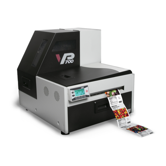
Parts of the Printer Media Cover Top Cover Output Slot Control Panel Front Cover GPIO Port USB Port Ethernet Port Power Socket Power Switch Using the Printer... -
Page 9: Using The Control Panel
Using the Control Panel The printer is ready to print when the control panel displays Printer Online. The Data and Status LEDs together with messages indicate the printer status and any potential problems (Table The control panel also shows the estimated levels of the ink cartridges. In the example below, the yellow ink cartridge level is between 25 to 50%. - Page 10 The icons above the printer buttons indicate their functions (Table • When the printer is online, press (Config) to access the configuration menus. The options are described in Config Options on the Control Panel on page 76. • Press to scroll through the menus. •...
-
Page 11: Selecting The Security Level
Selecting the Security Level By default, the printer powers up in security Level 0 (operator), which does not allow changes to some printer parameters. To make changes, select security Level 1 (supervisor) and enter the password provided by your administrator. Security Level 2 gives administrator access to all functions. -
Page 12: Choosing Label Media
Choosing Label Media Ensure that the label media meets the requirements for the printer (see Table 3 the following illustrations). Always test the media first to see if it meets your expectations. To check the compatibility of label media, print the barcodes test page. Table 3 Media specifications Media Type and Dimensions Media type... - Page 13 Figure 2 Gap (Transmissive) Media Minimum Maximum 0.125”(3.0 mm) 0.3” (8.0 mm) 2.0” (50.8 mm) 0.4” (10mm) 2.0” (50.8 mm) 8.5” (216.0 mm) 2.0” (50.8 mm) 40.0” (1016.0 mm) Figure 3 Black Mark (Reflective) Media Reverse side of tag stock Minimum Maximum 2.0”...
- Page 14 Print Test Page Load 4” x 4” or larger labels (with inter-label gap or continuous). MAINTENANCE PRINT TEST PAGE 1. On the control panel, select (Config) Barcodes. Sample Barcodes Test Page Printer Online (Config) CONFIGURATION 2. MAINTENANCE (Select) MAINTENANCE 1.
-
Page 15: Loading Label Media
Loading Label Media 1. Open the media cover. Loosen the knob and remove the roll cover. 2. Load the media roll. Replace the roll cover, with the flat side against the media roll. Then tighten the knob fully. 3. Feed the media under the arm and into the media feed slot. Wait for the printer to load the media. - Page 16 4. Close the media cover. Using the Printer...
-
Page 17: Printing Labels
Printing Labels The printer is ready to print when the control panel displays Printer Online. 1. Select the Print command from your application. 2. Select the printer and click the Setup, Properties or similar button. The print settings displayed are the defaults that were set in the printer driver. 3. - Page 18 Figure 4 Printing Preferences Print pages without any gap (continuous media only) Render entire document to disk before sending to the printer. Select this option if labels are skipped when printing large files. Select this option if labels are skipped when printing small labels.
-
Page 19: Select The Media Type
Select the Media Type Selecting the media type that matches the media you are printing on will usually give the best print results. Select this Media Type: When you are printing on: Plain Paper Plain (uncoated) paper and labels. Matte Coated Label Matte coated labels. -
Page 20: Adjust Alignment For Printing
Adjust Alignment for Printing Always print a few test labels to check the alignment of the image. If the image is not centered, adjust the top of form and/or left edge offsets on the Media tab of the printer driver. A positive value for Top of Form adjusts the image towards the top of the label. -
Page 21: Printing Borderless (Full-Bleed) Labels
The following procedure describes how to make the adjustments on the VP750/VP700 printer. Note the following: • This method requires fine-tuning of the printing position, which will be difficult if the label gap is very small e.g. -
Page 22: Saving Custom Media Size Settings
Saving Custom Media Size Settings Any custom media size settings will be lost if the printer driver is updated. Make a backup copy of these settings by exporting them to a file. Whenever the printer driver is updated, you can import the settings from the backup file. Export Custom Media Size Settings 1. -
Page 23: Turning Off The Printer
Turning Off the Printer Always use the Power button to turn off the printer. Removing power to the printer in any other manner may damage the printer. 1. Press the Power button on the control panel, then press (Select) to confirm. Printer Online SWITCH OFF 1. - Page 24 If the Printer Will Not Switch Off If the printer does not respond when you press the Power button, press and hold the power button for 5 seconds. The printer should switch off. However, it will not be able to perform the normal shutdown processes. Do not use this option unless it is absolutely necessary.
-
Page 25: Managing Printer Security (Administrator)
On the Windows Start menu, select All Programs > VIPColor > VIPColor VP750/VP700 Label Printer > Toolbox. b Click VIPColor VP750/VP700 Label Printer to launch the default web browser and open the EWS for your printer. c Click Login to log in with your admin password. - Page 26 3. Set the password and click Submit. • The EWS password can have 3 to 12 alphanumeric characters. Special characters are not allowed. • The control panel password must contain 3 digits. Change Security Level for Printer Settings The administrator can change the security level for the following protected printer settings, which are enabled at Level 1 by default.
-
Page 27: Embedded Web Server (Ews)
The administrator can also log in to view additional information and change various settings. 1. On the Windows Start menu, select All Programs > VIPColor > VIPColor VP750/VP700 Label Printer > Toolbox. - Page 28 The EWS contains the following pages: • Printer Status • Security Setup • Network Setup • Diagnostics • Advanced Settings Table 4 EWS: Printer Status EWS Page Description Information Shows printer and printhead information, and print counters. Control Panel – Click Launch to launch the remote control panel (Figure 6).
- Page 29 Table 5 EWS: Security Setup EWS Page Description Printer Password Set the passwords for accessing the following: • Embedded Web Server (EWS). • Level 1 (Supervisor) security on control panel. • Level 2 (Administrator) security on control panel. The EWS password can have 3 to 12 alphanumeric characters.
- Page 30 Adjusting Gap/Mark Sensor Thresholds 1. Load the media to be tested. 2. On the EWS Diagnostics page, under Sensor Threshold Values: a Select the test media type. b Specify the length of the label (min. 1”) and click Submit to apply the value. c Click TEST to run the test.
- Page 31 Advanced Settings • Advanced Settings 1 • Advanced Settings 2 • Import/Export Setting Table 7 EWS: Advanced Settings 1 EWS Page Description Select a command and click Submit to send it to the printer. Remote commands Mid Job Servicing For roll-to-roll print mode only Interval Select a servicing interval and click Submit.
- Page 32 Table 7 EWS: Advanced Settings 1 (continued) EWS Page Description Enable ink spit every Select this option to protect the printhead in a dry environment, characterized by 10 min in standby low humidity (~20% RH) and low temperature (~15°C or 59°F). mode Enable MM servicing When selected, servicing and error messages for the service station are displayed...
- Page 33 Table 7 EWS: Advanced Settings 1 (continued) EWS Page Description Display last job page When selected, the number of labels printed will be displayed on the front panel count when printer is until the next print job starts. idle Disable COM port When selected, the printer will ignore or not transmit signals through the COM port, which is used mainly for debugging.
- Page 34 Table 8 EWS: Advanced Settings > Advanced Settings 2 EWS Page Description • Pause Printer Pause Settings The printer will print labels at the selected time interval. • Print & Present Move the printhead to the capped position at the selected time interval after the last print.
- Page 35 Table 9 EWS: Advanced Settings > Import/Export Settings EWS Page Description Import Setting Import the Advanced Settings from another printer. Export Setting Export the Advanced Settings to another printer. Using the Printer...
-
Page 36: Other Support Tools
Other Support Tools On the Windows Start menu, select All Programs > VIPColor > VIPColor VP750/VP700 Label Printer > Support Tools. The Support Tools consist of the following: • Get Tech Support: Opens the Technical Support web page. • Buy Consumables: Opens the consumables web page for you to purchase ink supplies online. -
Page 37: Printer Maintenance
Chapter 2 Printer Maintenance Guidelines for Preventive Maintenance Replacing an Ink Cartridge Cleaning the Printhead Replacing the Printhead Opening/Closing the Clamshell Cleaning Debris from the Cutting Zone Cleaning the Sensors Replacing the Output Module/Cutter Assembly Replacing the Service Station Replacing the Transfer Wiper Assembly Replacing the Aerosol Fan Filter Replacing the Waste Ink Absorber Printer Maintenance... -
Page 38: Guidelines For Preventive Maintenance
Guidelines for Preventive Maintenance Recommended maintenance depends on the print mode that is most frequently used. If you mostly print Roll to Roll (≥80%), refer to Table 10. Otherwise, see Table 11. Inspect means to check the condition and replace if necessary. Note that these are general guidelines for preventive maintenance. -
Page 39: Replacing An Ink Cartridge
Replacing an Ink Cartridge Do not open the front cover if the control panel shows Servicing Printhead. Wait for the servicing to be completed first. 1. Open the front cover of the printer. 2. Open the latch and remove the empty ink cartridge. 3. -
Page 40: Cleaning The Printhead
Cleaning the Printhead The printer provides three automated cleaning cycles for the printhead: Normal, Extended, and Extreme. Always start with the Normal cleaning cycle and proceed to the next level only if print quality does not improve. PRINTHEAD CLEAN Normal.. 1. -
Page 41: Replacing The Printhead
Replacing the Printhead Make sure all the ink cartridges are installed before replacing the printhead. 1. Open the printer top cover. PRINTHEAD Replace. 2. On the control panel, select (Config) Printer Online (Config) CONFIGURATION 3. PRINTHEAD (Select) PRINTHEAD 2. - Page 42 3. When the printhead latch is released, open the latch fully. 4. Hold the printhead by the handle and push it toward the printhead latch. Once the printhead is released, lift it out of the printer. NOTE: Dispose of the old printhead according to local regulations. Printer Maintenance...
- Page 43 5. Remove the new printhead from its packaging. Do not touch the ink couplings, electrical contacts, or nozzles. ink couplings NOTE: Keep the orange cover. You will need it to cap the printhead if it is removed from the printer. nozzles electrical contacts No less than 45°...
- Page 44 7. Close the printhead latch. Check that ink is flowing through the tubes on both sides of the printhead. 8. Close the top cover. Printer Maintenance...
-
Page 45: Opening/Closing The Clamshell
Opening/Closing the Clamshell In the following procedures you may need to open the clamshell in order to access the areas inside the printer. Opening the Clamshell Do not open the top cover if the control panel shows Servicing Printhead. Wait for the servicing to be completed first. 1. - Page 46 Closing the Clamshell Squeeze and hold the clamshell latches while you gently lower the clamshell back into place. Do not allow the clamshell to drop when closing it. Printer Maintenance...
-
Page 47: Cleaning Debris From The Cutting Zone
Cleaning Debris from the Cutting Zone Clear all debris from the cutting zone to avoid contaminating the print zone, especially fine dust particles. 1. Open the top cover. 2. Vacuum any debris from the cutting zone (shown in green). cutter path Open the clamshell and also check below the cutting zone, at the bottom of the printer and in front of the ink cartridges. -
Page 48: Cleaning The Sensors
Cleaning the Sensors Always keep the media path clean as accumulated dust can affect printing. Open the clamshell to its highest position. 2. Vacuum any dust or debris from the sensors. Use the rollers to help you locate the sensors as shown in Figure 3. -
Page 49: Replacing The Output Module/Cutter Assembly
Replacing the Output Module/Cutter Assembly Tools • Nitrile powder-free gloves • Small flat-heat screwdriver • T10 Torx driver • Scissors or cutter (for cable ties) • Cable ties Keep the cutting zone free from debris. Check cut labels to ensure that the cuts have clean edges and replace the cutter assembly when necessary. - Page 50 Figure 8 Connectors and cables on left side of clamshell connector for output module connector for cutter assembly 5. Use a T10 Torx driver to remove the four screws securing the output module. Remove the outer screws (a) first. 6. Carefully remove the output module from the clamshell. There is a black cable looped across the bottom of the output module.
- Page 51 Replace Cutter Assembly If replacing the cutter assembly, continue with the following steps. 1. Use a small flat-head screwdriver to release the wire harness connector for the cutter assembly (labeled CUTTER MODULE) and separate it (Figure 2. Remove the two screws (a) securing the cutter assembly and remove the assembly (Figure Figure 9 Cutter assembly on clamshell...
- Page 52 Installation 1. Seat the output module on the cutter assembly, aligning the mounting holes for the screws. 2. Loop the black cable over the bottom of the output module, pushing it back into the notches at the corners of the cutter assembly. 3.
-
Page 53: Replacing The Service Station
Replacing the Service Station NOTE: Before you begin, remove the printhead and cap it with the orange protective cover. Tools • Nitrile powder-free gloves • T20 Torx driver • Disposable towels Removal Open the clamshell to its highest position. SERVICE STATION Eject. - Page 54 5. Pull the service station forward until you can disconnect the flex cable to the wiper motor. Loosen the clip on the connector (Figure 10) to release the flex cable. flex cable Ensure that the flex cable does not come into contact with any metallic surface.
- Page 55 7. Carefully align the service station with the guide rails and slide it into the print engine. Push it in by applying even pressure near the edges, to ensure that the it goes in straight. guide rail Check the alignment: the cap on the service station must be parallel with the edge of the platen as shown below.
-
Page 56: Replacing The Transfer Wiper Assembly
Replacing the Transfer Wiper Assembly Removal 1. Follow the instructions to remove the service station. 2. Disconnect the wiper motor cable from the PCB. 3. Release the PCB from the mounting clip. mounting clip wiper motor cable 4. Route the cable through the housing as you remove the transfer wiper assembly. wiper roller NOTE: Dispose of the old transfer wiper assembly according to local regulations. - Page 57 Installation 5. Route the wiper motor cable through the housing as you insert the new transfer wiper assembly into the service station. 6. Push the cable between the clips. Align the PCB with the mounting clip and push gently into place. 7.
-
Page 58: Replacing The Aerosol Fan Filter
Replacing the Aerosol Fan Filter You can replace the aerosol fan guard or just replace the fan filter. Tools • Nitrile powder-free gloves • Flat-head screwdriver To replace the fan filter: Open the clamshell to its highest position. 2. Insert the tip of a flat-head screwdriver into the slot at the corner of the aerosol fan guard, and pry the cover off. -
Page 59: Replacing The Waste Ink Absorber
Replacing the Waste Ink Absorber Tools • Nitrile powder-free gloves 1. Open the front cover of the printer. 2. Squeeze the latches on both sides of the waste ink tray and pull it out. 3. Remove the waste ink absorber and replace it with a new one. 4. - Page 60 Printer Maintenance...
-
Page 61: Troubleshooting
Chapter 3 Troubleshooting If Error Messages Appear Poor Print Quality or Incorrect Printout Other Printing Problems Clearing a Media Jam Clearing Clogged Ink Nozzles Adjusting Sensor Sensitivity Troubleshooting... -
Page 62: If Error Messages Appear
If Error Messages Appear If error messages are displayed on the printer control panel, check the following table for the solution. Error Message Possible Cause Solution Clamshell Open The clamshell is open. Close the clamshell. The clamshell sensor is damaged Contact Technical Support for part replacement. - Page 63 Error Message Possible Cause Solution Mech Error [code] Printer mechanical fault. Note the error code and contact Technical where [code] > 01 Support. If Mech Error 2 or Mech Error 3a/3b appears during installation, see Troubleshoot Printer Setup on page 65. Do not attempt to restart the printer more than 3 times if the same Mech Error appears.
- Page 64 Error Message Possible Cause Solution No Media No media is detected. Load a new roll of labels. The media is not properly inserted Re-load the media. into the input guide. Wrong Media Problems with the media. Printer feeds media without printing page 69.
- Page 65 Table 12 Troubleshoot Printer Setup Possible Cause Solution Service station is jammed. Ensure that the cardboard is removed from inside the printer. Service station was tilted 1. Turn off the printer: Press the Power button on the control panel, then during shipment.
-
Page 66: Poor Print Quality Or Incorrect Printout
Poor Print Quality or Incorrect Printout Problem Possible Cause Solution Long stripes of missing Ink nozzles are clogged. Clearing Clogged Ink Nozzles on page 70. print or vertical light streaks on several labels Printed barcode cannot The media is not suitable for Replace the media. - Page 67 Problem Possible Cause Solution Mixed or muddy colors The printhead is dirty. 1. Run Extended cleaning cycle from the control MAINTENANCE panel ( (Config) CLEAN Extended). If print quality shows some improvement, repeat Extended cleaning until the print quality is satisfactory.
- Page 68 Problem Possible Cause Solution Mis-registration or Media settings do not match Make sure the settings are correct for the media labels are skipped the media loaded in the printer. (e.g. media size and orientation). The media does not meet the Choosing Label Media on page 12 for the specifications.
-
Page 69: Other Printing Problems
Other Printing Problems Problem Possible Cause Solution Printer feeds media without Media settings do not match Make sure the Media Layout setting (gap, printing and then displays the media loaded in the black mark, or continuous) in the printer Wrong media on the LCD. printer. -
Page 70: Clearing A Media Jam
Clearing a Media Jam 1. Open the media cover. 2. Cut off the jammed media from the media roll. Open the clamshell to its highest position. 4. Remove the jammed media from inside the printer. Close the clamshell and top cover. 6. - Page 71 2. From the control panel, run Normal printhead cleaning. MAINTENANCE CLEAN Normal) (Config) • If print quality shows some improvement, repeat Normal cleaning until the print quality is satisfactory. • If print quality does not improve, continue with step 3.
-
Page 72: Adjusting Sensor Sensitivity
Adjusting Sensor Sensitivity Adjust the sensor sensitivity if you encounter the following problems: • The printer keeps feeding media and does not print. This may be because the printer is unable to detect the gap or black mark between labels and the sensor sensitivity needs to be increased. -
Page 73: Appendix
Appendix System Requirements Config Options on the Control Panel Printer Interface (GPIO) Specifications Regulatory Information Worldwide VIPColor Technologies Contacts Appendix... -
Page 74: System Requirements
System Requirements The computer used to print must meet the minimum requirements listed below. Specifications Processor Intel® Core™2 and above Operating system Supported operating systems with the latest updates: • Windows 10 (32- and 64-bit) • Windows 8 (32- and 64-bit) •... - Page 75 3. Select the .NET Framework 3.5.1 entry and click Next. 4. Confirm the installation by clicking Install. 5. When installation is complete, click Close. You may be prompted to restart the computer. Appendix...
-
Page 76: Config Options On The Control Panel
Config Options on the Control Panel On the control panel, press (Config) to access the following menus and options. Some settings require security Level 1 or Level 2 (see Selecting the Security Level page 11). Menu/Option Description SETUP Language Select the display language for the printer control panel. Supported languages are: English, French, German, Spanish, Italian, Traditional Chinese, Simplified Chinese, and Japanese. - Page 77 Menu/Option Description Page Cutting Select the printer default print mode. The available modes are • Sheet per cut • Print and Present • Roll to Roll (Leave first label blank) • Roll to Roll (Print from first label) • Roll to Roll (Multiple job queue When the use printer setting is selected in the driver, the printer will use this mode.
- Page 78 Menu/Option Description EXT SIGNAL PRINT By I/O When this option is selected, the printer receives the print job but will not print until it receives a signal from an external device. Printer Interface (GPIO) Specifications on page 81. Appendix...
- Page 79 Menu/Option Description ADJUST OFFSET Offset range: ±0.5” or ±12.7 mm. Use these options for borderless printing only. Left Edge – Top of Form: – Bottom of Form: – Top of Form Adjust the starting line of the image. Bottom of Form Adjust the ending line of the image.
- Page 80 Menu/Option Description NETWORK List Network Print the network setup parameters which will fit neatly on a 4” x 4” label (with inter-label gap or continuous as specified in the EWS Diagnostics page). DHCP Setting Set the IP settings on the printer. •...
-
Page 81: Printer Interface (Gpio) Specifications
Printer Interface (GPIO) Specifications The Printer Electrical Signal Interface and Protocol is developed to coordinate the printing of labels with an external process in a production workflow. Using this protocol, the printer (Device A) receives a print job but will not print until it receives a signal from an external device (Device B). - Page 82 Figure 13 Timing Diagram Table 13 GPIO Pin Assignment (D-sub 9-pin Connector) Signal Description HIGH (3.3 V) ADC 5 Print job ready (output) (GPIO A25) External device ready (input) (GPIO D04) Printer error (output) (GPIO D08) LOW (0 V) Appendix...
-
Page 83: Regulatory Information
Regulatory Information FCC Statement NOTE: This equipment has been tested and found to comply with the limits for a Class A digital device, pursuant to Part 15 of the FCC Rules. These limits are designed to provide reasonable protection against harmful interference when the equipment is operated in a commercial environment. - Page 84 声明 此为 A 级产品,在生活环境中该产品可能会造成无线电干扰。在这种情况下,可 能需要用户对其干扰采取切实可行的措施。 警告使用者 這是甲類的資訊產品,在居住的環境中使用時可能會造成射頻干擾 : 在這種情況 下,使用者會被要求採取某些適當的對策。 VP750/VP700 产品 : 有毒和危险物品表 按照电子信息产品中国污染控制管理方法的要求 (依据 SJ/T11363-2006 标准) 有毒和危险物品 铅 水银 镉 六价格 多溴化苯 多溴化二苯醚 部件名称 (Pb) (Hg) (Cd) (PBB) (PBDE) 外部表面,隔板以及底盘 PCAs 以及电气元件 电缆线材 光学系统 转轴 液压 / 气压系统...
- Page 85 VP750/VP700 限用物質含有情況標示聲明書 限用物質及其化學符號 Restricted substances and chemical symbols 鉛 汞 鎘 六價鉻 多溴聯苯 多溴二苯醚 單元 Unit Lead Mercury Cadmium Hexavalent Polybrominate Polybrominated (Pb) (Hg) (Cd) chromium d biphenyls diphenylethers (Cr(VI)) (PBB) (PBDE) 外殼,隔板以及 底盤 PCAs 以及電氣 元件 電纜線材 光學系統 轉輥和滾筒...
-
Page 86: Worldwide Vipcolor Technologies Contacts
Worldwide VIPColor Technologies Contacts VIPColor Technologies USA, Inc. 41300 Boyce Road Newark CA 94538, USA Phone: +1 510 744 3770 www.vipcolor.com/us Venture Electronics Spain S.L. C Pagesia, 22-24 08191 Rubí Barcelona, Spain Phone: +34 93 588 3018 www.vipcolor.com/uk VIPColor Technologies Pte Ltd 5006 Ang Mo Kio Avenue 5 #05-01/12 TECHplace II Singapore 569876...
Need help?
Do you have a question about the VP750 and is the answer not in the manual?
Questions and answers