Table of Contents
Advertisement
SERVICE
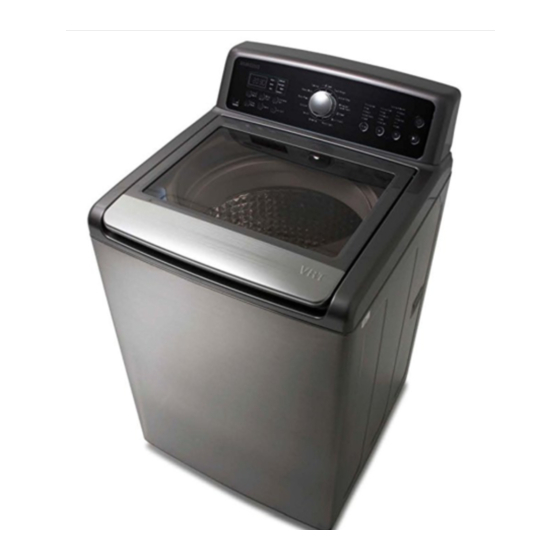
WASHING MACHINE (TOP-LOADING)
WA5451*
Refer to the service manual in the GSPN (see the rear cover) for the more information.
WASHING MACHINE
TOP-LOADING TYPE
Model Name : WA5451AB*
(ORCA PROJECT)
Model Code : WA5451ABW/XAA
Manual
1. Safety Instructions
2. Features and Specifications
3. Disassembly and Reassembly
4. Troubleshooting
5. PCB Diagram
6. Wiring Diagram
7. Schematic Diagram
CONTENTS
Advertisement
Table of Contents

Related Manuals for Samsung WA5451AB Series


Summary of Contents for Samsung WA5451AB Series
- Page 1 WASHING MACHINE TOP-LOADING TYPE Model Name : WA5451AB* (ORCA PROJECT) Model Code : WA5451ABW/XAA SERVICE Manual WASHING MACHINE (TOP-LOADING) CONTENTS 1. Safety Instructions 2. Features and Specifications 3. Disassembly and Reassembly 4. Troubleshooting 5. PCB Diagram 6. Wiring Diagram 7. Schematic Diagram WA5451* Refer to the service manual in the GSPN (see the rear cover) for the more information.
-
Page 2: Table Of Contents
CONTENTS 1. Safety instructions ..............1 1-1. -
Page 3: Safety Instructions
1. SAfETY INSTRuCTIONS 1-1. SAfETY INSTRuCTIONS fOR SERVICE ENGINEERS ► Be sure to observe the following instructions to operate the product correctly and safely to prevent possible accidents and hazards while servicing. ► Two types of safety symbols, Warning and Caution, are used in the safety instructions. Hazards or unsafe practices that may result in severe personal injury or death. WARNING Hazards or unsafe practices that may result in minor personal injury or property damage. CAuTION WARNING BEfORE SERVICING... - Page 4 WARNING WHILE SERVICING • Check if the power plug and outlet are damaged, flattened, cut or otherwise degraded. 4 If faulty, replace it immediately. Failing to do so may result in electric shock or fire. • Completely remove any dust or foreign material from the housing, wiring and connection parts. 4 This will prevent a risk of fire due to tracking and electrical hazard.. • When connecting wires, make sure to connect them using the relevant connectors and check that they are completely properly. 4 If tape is used instead of the connectors, it may cause fire due to tracking. • Make sure to discharge the PBA power terminals before starting the service. 4 Failing to do so may result in a high voltage electric shock. • When replacing the heater, make sure to fasten the nut after ensuring that it is inserted into the bracket-heater. 4 If not inserted into the bracket-heater, it touches the drum and causes noise and electric leakage. WARNING AfTER SERVICING • Check the wiring. 4 Ensure that no wire touches a rotating part or a sharpened part of the electrical harness. • Check for any water leakage.
- Page 5 CAuTION BEfORE SERVICING • Do not sprinkle water onto the washing machine directly when cleaning it. 4 This may result in electric shock or fire, and may shorten the product lifetime. • Do not place any containers with water on the washing machine. 4 If the water is spilled, it may result in electric shock or fire. This will also shorten the product lifetime. • Do not install the washing machine in a location exposed to snow or rain. 4 This may result in electric shock or fire, and shorten the product lifetime. • Do not press a control button using a sharp tool or object. 4 This may result in electric shock or damage to the product. CAuTION WHILE SERVICING • When wiring a harness, make sure to seal it completely so no liquid can enter. 4 Make sure that they do not break when force is exerted. • Check if there is any residue that shows that liquid entered the electric parts or harnesses. 4 If any liquid has entered into a part, replace it or completely remove any remaining moisture from it. • If you need to place the washing machine on its back for servicing purposes, place a support(s) on the floor and lay it down carefully so its side is on the floor. 4 Do not lay it down on its front. This may result in the inside tub damaging parts. Safety Instructions _ 3...
- Page 6 CAuTION AfTER SERVICING • Check the assembled status of the parts. 4 Now is a good time to inspect your work. Review all connections and wiring, including mounting hardware. • Check the insulation resistance. 4 Disconnect the power cord from the power outlet and measure the insulation resistance between the power plug and the grounding wire of the washing machine. The value must be greater than 10MΩ when measured with a 500V DC Megger • Check whether the washing machine is level the floor with respect to the original position of the washing machine prior to service. By doing this now will reduce for the need of customer dissatisfaction and redo call.
-
Page 7: Features And Specifications
2. fEATuRES AND SPECIfICATIONS 2-1. fEATuRES features Description VRT® • This Samsung washer performs smoothly at top spin speeds, minimizing noise and vibration. (Vibration Reduction Technology) • Even bulky garments and blankets get super clean. The Largest Capacity The large capacity leaves enough room for a more thorough, cleaner wash. • Clean your drum with one button! PureCycle™ This Pure Cycle is specially designed to remove detergent residue & dirt (Tub Cleaning cycle) bulidup in the tub, without the need for special chemical detergents. -
Page 8: Specifications
2-2. SPECIfICATIONS TYPE TOP LOADING WASHER A. Height 44.6 " / 1135 mm B. Width 27 " / 686 mm DIMENSION (Inches / cm) C. Height with Door open 57.5 " / 1465 mm D. Depth 28.6 " / 728 mm WATER PRESSURE 137~800 kpa (20 psi ~116 psi) WEIGHT... -
Page 9: Detail Features
2-3. DETAIL fEATuRES Grade WA5471 * WA5451* Image Capacity (IEC) Diamond interior drum PureCycle™ Washing Cycles Main Spec Internal heater VRT® Pulsator material Max rpm 1,100 1,100 Motor DD motor DD motor Color Stainless Platinum Neat White Center display 88:88 88:88 Jog Dial Grace Same Grace Same... -
Page 10: Options Specifications
2-4. OPTIONS SPECIfICATIONS Item Item Name Code No. Remark ASSY-HOSE WATER (C) DC97-15648A Default ASSY-HOSE WATER (H) DC97-15648B Default HOSE-HANGER DC62-10278A Default MANUAL-BOOK DC68-03050A Default Note • You can purchase additional water supply and drain hoses from a service center. 8 _ Features and Specifications... -
Page 11: Disassembly And Reassembly
3. DISASSEMBLY AND REASSEMBLY 3-1. TOOLS fOR DISASSEMBLY AND REASSEMBLY Tool Type Remarks Heater(1),Tub(16), Fixer screw(5), Motor(1), 10mm Balance(5) Box driver 17mm Damper(2), Damper(friction 1) 10mm Replaced by box driver Double-ended spanner 17mm A Tool for protecting empty turning of bolt or abrasion from using box driver Vice pliers For disassembly of Spin drum Others Common tools for servicing (screwdriver, nipper,... -
Page 12: Standard Disassembly Drawings
3-2. STANDARD DISASSEMBLY DRAWINGS ► This is a standard disassembly diagram and may differ from the actual product. Use this material as a reference when disassembling and reassembling the product. Part figure Description 1. Remove the 2 screws holding the control panel assembly and turn the panel over. Sub PCB Assembly 2. Separate the wire connected to the sub PCB. 3. - Page 13 Part figure Description 1. After separating the control panel, separate the water-valve housing. 2. Remove the 3 fixing screws and remove the screw from the main PCB. Water Valve 3. Remove the wire-harness and release the 4 clamps connecting the hoses. When releasing the clamps, take care that you do not tear the hoses. Disassembly and Reassembly _ 11...
- Page 14 Part figure Description 1. Separate the control panel. 2. Separate the water valve housing. 3. Remove the 4 screws holding the bracket frame. 4. Lift the top cover assembly and leave it at a slant. 5. Use a pair of pliers to pull down the holder shaft.
- Page 15 Part figure Description 1. Remove the 4 screws from the frame-bracket (U/L). 2. Separate the control panel assembly. 3. Separate the water valve, the main PBA, the pressure switch and the filter EMI housing. Top Cover Separate the housing to prevent stress and Assembly damage to the wire-harness. / Door Switch 4. Separate the main wire hareness, the pressure switch hose clip , Gnding screw . 5. Release the bleach hose clamp. 6.
- Page 16 Part figure Description 1. Place the frame in such a way that the front faces left. 2. Disconnect the wire next to the circulation pump. Circulation - Pump 3. Remove the circulation pump housing. 4. Remove the 6 screws. 5. Separate the pump cover. 1. Separate the connector. MEMS 2.
- Page 17 Part figure Description 1. Remove the 2 screws holding the panel control Separate all the wires connected to the housing. 2. Remove the 4 screws fixing the tub-cover, release the hook on the side, and separate the tub-cover. Clutch Assembly (continued) 3. Separate the pulsator-cap by inserting the tip of a (-) screwdriver between the pulsator- cap and the pulsator and then lifting the screwdriver up (↑).
- Page 18 Part figure Description 4. Remove the bolt holding the pulsator with a 10mm wrench. Clutch Assembly (continued) 5. Remove the shaft with the jig wrench. - Release the nut in a clockwise direction. - Fasten the nut in a counterclockwise direction. 6. Place the main body so that the front frame faces upward and remove the 4 bolts holding the saddle with a 10mm wrench.
- Page 19 Part figure Description 7. Remove the bolt holding the DD-motor housing with a 17mm wrench and then remove the motor housing. 8. Remove the 6 bolts holding the DD-motor with a 10mm wrench. Clutch Assembly (continued) 9. Separate the 2 marked housings and then remove the DD-motor. 10. Press the hook to separate the housing.
- Page 20 Part figure Description 11. Separate the slide guide and the coupling by pulling them forward. Disassemble the coupling and the spring. 12. Remove the 2 screws holding the drain motor. 13. Remove the 5 screws holding the slide guide assembly. Clutch Assembly (continued) 14.
-
Page 21: Troubleshooting
4. TROuBLESHOOTING 4-1. ERROR MODES ► This is a washer integrated error mode. for detailed information, refer to the general repair scripts. for uSA Error Type Causes Remarks The part of the hose where the water level sensor is located is damaged (punctured). The hose is clogged with foreign material. - Page 22 for uSA Error Type Causes Remarks A switch contact error because of a deformation of the When the door is opened after starting door hook (Before operation operation) When the door is pulled by force - The door lock switch terminal is connected incorrectly. Door Error (Unlock - The door lock switch terminal is broken. Fail) This occurs intermittently because of an electric wire leakage...
- Page 23 for uSA Error Type Causes Remarks - After the completion of the clutch position detection, and the clutch hall signal is invalid, the spin drum is 1. Check the clutch hall sensor. shaken left and right and then the clutch hall signal is 2. Check the wire connector terminals. clutch motor evaluated again. hall sensor 3. Check the clutch switching status. This, if the clutch hall signal is still invalid,the clutch error - Check the coupling assembly and position switching status is checked and then the disassembly status. operation is restarted.(If the 15 reattempts fail, this error occurs.) If the output from the MEMS sensor is over 4.5V or 1. Check the MEMS sensor and PBA. MEMS error under 0.5V and it continues for 5 seconds, this error 2. Check the wire connector terminals...
-
Page 24: Corrective Actions For Each Error Code
4-2. CORRECTIVE ACTIONS fOR EACH ERROR CODE 22 _ Troubleshooting... - Page 25 Troubleshooting _ 23...
- Page 26 24 _ Troubleshooting...
- Page 27 Troubleshooting _ 25...
- Page 28 26 _ Troubleshooting...
-
Page 29: Pcb Diagram
5. PCB DIAGRAM 5-1. MAIN PCB Location Part No. function Description Location Part No. function Description TE1~4 IC15 Motor Control Control to Motor RY8~10 Load Control Turn ON/Off the Load(Valve etc.) SSR1 RY12 Main Relay Main Power Relay Door Lock Switch • Drive the Door Lock Switch RY1,Q5 FUSE Limit the Over-Current... -
Page 30: Detailed Manual For Connector And Relay Terminal Part (Main Pcb)
5-2. DETAILED MANuAL fOR CONNECTOR AND RELAY TERMINAL PART (MAIN PCB) ► CN3 1 Door Lock Motor 2. Door Lock Motor 3. GND 4. Unlock Contact 5. Lock Contact 6. Reed Switch 7. 5V-1 ► CN2 1. Standby 2. TX 3. -RX 4. Reset 5. 5V-IS 6. GND 7. -
Page 31: Sub Pcb
5-3. SuB PCB Location Part No. function Description Micom1 Control Function Control Key and LED Function Sensing Thermistor , Water Lavel and vibration Jog Dial Jog Dial Communication Part Connect Main PBA Conecting Sensing Part Connecting Thermistor , Water Lavel and Mems Sensor LED1~28 LED Lamp Display Function Buzzer Making a sound SW2~6 Switch Operating or changing Function PCB Diagram _ 29... -
Page 32: Detailed Manual For Connector Terminal Part (Sub Pcb)
5-4. DETAILED MANuAL fOR CONNECTOR TERMINAL PART (SuB PCB) ► CN2, CN10 All Of Pin Connected Display & Key scan Part ► CN9 ► CN8 ► CN7 1. Sub Reed 1. 3.3V-Mems 1. U3.3V 2. Water Level 2. SPC 2. Reset 3. -
Page 33: Dsp Pcb
5-5. DSP PCB Location Part No. function Description DSP1 LED Display Display Function LED1~28 Display Display Function CN1,2 Connector Connecting Sub PBA SW1~6 Switch Operating or changing Function PCB Diagram _ 31... -
Page 34: Detailed Manual For Connector Terminal Part (Dsp Pcb)
5-6. DETAILED MANuAL fOR CONNECTOR TERMINAL PART (DSP PCB) ► CN1, CN2 All Of Pin Connected Display & Key scan Part 32 _ PCB Diagram... -
Page 35: Wiring Diagram
6. WIRING DIAGRAM 6-1. WIRING DIAGRAM (WA5471* / WA5451*) n REfERENCE INfORMATION BLACK BLUE GREEN GRAY NATURAL ORANGE PINK SKYBLU SKYBLUE VIOLET WHITE YELLOW Wiring Diagram _ 33... -
Page 36: Schematic Diagram
7. SCHEMATIC DIAGRAM 7-1. MAIN CONTROL (WA5471* / WA5451*) ► This Document can not be used without Samsungs authorization. +15V +15V KIA7805AF +12V-IS JUMP DC_LINK DC_LINK BST-06-52 CE11 IC12 PTC1 47uF 100nF +15V AC1-1 +5V-IS AC1-1 ES3D ES3D CE12 PTC2 200V 3A CE17 CE16 CE15 R125 1000uF IC15 47uF 47uF 47uF... -
Page 37: Sub Control (Wa5471* / Wa5451*)
7-2. SuB CONTROL (WA5471* / WA5451*) ► This Document can not be used without Samsungs authorization. +3.3V BKGD +3.3V WATER_THERM WATER_THERM REED_2 REED_2 100nF BZ_ENA BZ_ENA RESET RESET POWER_ON POWER_ON BKGD 1M J 0.125W MEMS_POWER MEMS_POWER BKGD SMW250-04DW XOUT XOUT AD10011608 10MHz +3.3V +3.3V 0.022nF 0.022nF REED_1 +3.3V REED_1 PTC4 PTG3/KBI1P3... -
Page 38: Dsp Control (Wa5471* / Wa5451*)
7-3. DSP CONTROL (WA5471* / WA5451*) ► This Document can not be used without Samsungs authorization. PURPLE_PJT DSP1 LED3 9 10 11 12 DGD-D5818V-A LED2 3.1mm RED LED1 3.1mm 3.1mm LED7 LED6 LED5 LED4 LED11 3.1mm 3.1mm 3.1mm 3.1mm 3.1mm LED10 LED9 LED8 3.1mm 3.1mm 3.1mm PURPLE_PJT SW3 SW6 SW5 36 _ Schematic Diagram... - Page 39 GSPN (GLOBAL SERVICE PARTNER NETWORK) Area Web Site America http://gspn3.samsungcsportal.com Europe, MENA, CIS, Africa http://gspn1.samsungcsportal.com China, Asia, Japan http://gspn2.samsungcsportal.com © 2012 Samsung Electronics Co.,Ltd. All This Service Manual is a property of Samsung Electronics Co.,Ltd. rights reserved. Any unauthorized use of Manual can be punished under applicable Printed in Korea International and/or domestic law. Code No.: DC68-02839A...