biodex 850-000 Instructions For Use Manual
Multi-joint system
Hide thumbs
Also See for 850-000:
- Installation instructions manual (16 pages) ,
- Instructions for use manual (108 pages)

Related Manuals for biodex 850-000


Summary of Contents for biodex 850-000
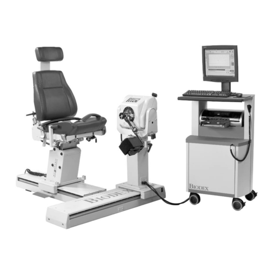
- Page 1 BIODEX MULTI-JOINT SYSTEM INSTRUCTIONS FOR USE 850-000, 840-000, and 852-000 FN: 18-142 5/18...
- Page 2 840-000, and 852-000. Additional information and resources are available upon request or directly from the Biodex website, http://www.biodex.com. If the desired information is not found, please feel to contact a local distributor or Biodex directly at supportservices@biodex.com Thank you, Biodex Medical Systems...
-
Page 3: Table Of Contents
Table of Contents Product Certifications and Classifications ................... 5 Warnings and Cautions ......................6 Important Safety Information ..................6 Introduction ........................8 Multi-Joint System ......................8 Dynamometer ........................ 9 Positioning Chair ......................12 ... - Page 4 Definition of Symbols The following symbols and their definitions are used and implied throughout this manual. Definition Symbol Read instructions before using this product. Caution Warning Mandatory Action Dangerous Voltage On Power Pinch Point Off Power Earth (ground) Alternating Current Fuse USB Connector/Cable Waste in Electrical Equipment...
-
Page 5: Product Certifications And Classifications
Service (see Contact information). Note: Complete information on the Electromagnetic Compatibility for the Multi-Joint System can be located in the Compliance Supplement located on the Biodex website (www.biodex.com) or can be obtained by contacting Biodex Customer Service (see Contact information). -
Page 6: Warnings And Cautions
It may also help to have a fixed location from which all subjects approach and leave the chair. Be aware that use of Biodex technology requires professional expertise for • discerning appropriate treatment techniques. Each subject’s unique situation should be taken into account before beginning any type of testing or rehabilitation program. - Page 7 To relocate the system, the system is disconnected from power source. Use the wheels to move the system. Contact information Manufactured by: Biodex Medical Systems, Inc. 20 Ramsey Road, Shirley, New York, 11967-4704 Tel: 800-224-6339 (Int’l 631-924-9000) Fax: 631-924-8355 email: supportservices@biodex.com...
-
Page 8: Introduction
1. Introduction Indications for Use The Multi-Joint System is used to identify, treat, and document the physical impairments that cause functional limitations typical of sports injuries, orthopedics, pediatric medicine, and neurorehabilitation. Contraindications What are the contraindications to isokinetic testing or exercising? Absolute Contraindications: Acute strain (musculotendinous unit) or sprain (non contractile tissue) •... -
Page 9: Dynamometer
COMFORT STOP Figure 1.2. Dynamometer positioning controls and adjustments. Rotation Knob Tilt Knob Height Lever Foot Pedals (travel) (850-000, 840-000) Shaft Red Dot (on dynamometer shaft) Rotate Counterclockwise Button Rotate Clockwise Button Hold/Resume Button Comfort Stop 10. Locking Knob Storage 11. - Page 10 After proper height is established, always secure the locking handle. Dynamometer Travel (850-000, 840-000): The Foot Pedals allow the dynamometer to move along the travel in a horizontal plane left or right of the positioning chair. To move the dynamometer, press down on either foot pedal and slide the dynamometer to the desired location.
- Page 11 Comfort Stop. A second Hold/Resume button is activated by a hand-held remote located to the right of the control panel on the Clinical Data Station (CDS) cart. CAUTION: Comfort Stops (Dynamometer, Remote): These buttons provide the subject with the ability to instantaneously terminate exercise in any mode.
-
Page 12: Positioning Chair
Indicator, located at the bottom on either side of the seatback frame. Seat Height (850-000): The motorized seat may be automatically raised or lowered over a range of 14 inches. To adjust the seat height, step down on the <▲> or <▼> Seat Height Foot Switches, located at the rear base of the chair. - Page 13 NOTE: Be sure to support the Cervical Support with one hand before loosening the locking knob. If the Cervical Support is not supported, it may slide down and pinch a hand as the knob is loosened. Stabilization Straps: The Positioning Chair is fitted with a Thigh Strap and Buckle (secured toward the front on each side of the seat frame), a Pelvic Strap and buckle (secured directly beneath the Seatback Tilt handle on the seat back frame,) and a pair of Shoulder Straps and buckles (secured toward the back on each side of the seat base).
- Page 14 Figure 1.3. Positioning Chair Adjustments (850-000). Seat Rotation Handle Receiving Tubes Chair Foot Pedals Seat Height Foot Switches Cervical Support Adjustment Knob Seatback Tilt Handle Seatback Fore/Aft Handle Stabilization Handles...
-
Page 15: Seatback Brace
Figure 1.4. Positioning Chair Attachments: T-Bar Adapter Footrest Limb-Support Pad Seatback Brace The Seatback Brace is designed to provide added stability when the seatback is used in a lowered position at zero degrees seat rotation for side lying, supine and prone patterns (particularly of the hip). -
Page 16: The Controller
4. Loosen the Seatback Brace locking knob. Extend the lower part of the brace and insert the rod-end swivel into the trolley mount clevis. Insert the clevis pin. 5. Position the patient per protocol; lock the Seatback Brace locking knob to secure. -
Page 17: Dynamometer Attachments
Status/Diagnostics Panel (LEDs): This panel provides information to assist in troubleshooting of dynamometer/control panel problems. In the event of a system malfunction, always be sure to record that LEDs light before attempting to correct a problem or restart the system. Contact a Service Representative whenever the status panel indicates a malfunction. - Page 18 Patterns: Shoulder: Ex/Flex Ab/Ad Diagonals Figure 1.9. Shoulder/Elbow Attachment (Insert in Shoulder/Elbow Adapter) Patterns: Shoulder: In/Ex Rotation Elbow: Ex/Flex (remove cuff) Note: Only one Shoulder/Elbow Adapter is supplied. The same adapter is used with the Shoulder Attachment and Shoulder/Elbow Attachment. Figure 1.10.
- Page 19 Wrist Attachment Wrist Adapter Figure 1.11. Wrist Attachment Patterns: Wrist: Ex/Flex Radial/Ulnar Deviation Forearm: Pro/Supination Figure 1.12. Hip Attachments (Left and Right) Patterns: Hip: Ab/Ad Ex/Flex CAUTION: Ensure finger guard is in place when using this attachment. See Figure 1.16.
- Page 20 Figure 1.13. Combination Ankle Attachment Patterns: Ankle: Plantar/Dorsi Flexion Inversion/Eversion Note: See Using the Combination Ankle Attachment (next section). Figure 1.14. Finger Guard Positioned Correctly on Dynamometer for Knee and Hip Attachments. Patterns: Knee: Ex/Flex CAUTION: Placing hands or fingers between the dynamometer input shaft (or attachment) and the mechanical ROM stops may result in serious injury.
-
Page 21: Using The Combination Ankle Attachment
Using the Combination Ankle Attachment G D A h B E C F Figure 1.15. The Combination Ankle Attachment Adjustment Mechanisms. A. Footplate Rotation Lever B. Footplate Tilt Lever C. Heel Cup Release Buttons D. - Page 22 tags per test or exercise protocol by aligning the white “P” with the red dot for plantar\dorsiflexion or the green “I” to the red dot for Inversion\Eversion. Tighten the lever to secure the footplate in place. Heel Cup Position: To facilitate alignment of the subject’s axis of rotation with the dynamometer shaft, it may be necessary to raise or lower the patient’s foot on the footplate by adjusting the heel cup position.
-
Page 23: Operation
2. Operation Considerations for Safe Operation of the Multi-Joint Systems: 1. The clinician should always be present during testing or exercise sessions. Do not allow subjects to test or exercise by themselves. 2. Range limits should always be set after the subject is positioned according to protocol and before switching to a test or exercise mode. -
Page 24: Readying The System For Use
Dynamometer Operation screen. The message “Set ROM Limits” should now be displayed in the System Status window at the top of the screen. The system is now ready for use. Note: Should a coded initialization error message be displayed, contact Biodex Customer Service. - Page 25 Biofeedback Operation – Biofeedback Operation incorporates all the functions that, in earlier versions of Multi-Joint Systems, were controlled by the front panel. In this mode, clinicians can set up and begin patient exercise without entering patient-specific data such as name, address, weight, etc.
- Page 26 reached. In Passive mode, the dynamometer initiates motion when the <Start> button is pressed, requiring no active participation by the subject. Passive Mode Clinical Applications: 1. The Passive mode is frequently used post-operatively for the benefits of continuous passive motion, which assist with nourishment of the joint. 2.
- Page 27 Isometric Mode – In this mode, the dynamometer maintains zero velocity at any selected point in the range of motion. Significant change in joint angle and overall muscle length does not occur. Isometric Mode Clinical Applications: 1. The Isometric mode may be used pre- or post-surgery with discretion. 2.
-
Page 28: Additional Considerations
a window of 90 ft-lb (122.4Nm). Reactive Eccentric mode allows for direction changes at any point in the range of motion. Reactive Eccentric Mode Clinical Applications: 1. The Reactive Eccentric mode may be used to perform submaximal or maximal eccentrics. 2. -
Page 29: Proper Testing Technique
7. The Multi-Joint System is a versatile piece of equipment, making it difficult to document every possible setup position. If a non-documented position is used, document it. If it becomes a position that is used often, send the information to Biodex. Proper Testing Technique 1. -
Page 30: Software Operation
3. Software Operation Patient Selection Window This window is used to keep track of the patient's general information and test history. The Patient Selection Window displays information such as general patient information, admission dates, release dates, as well as diagnosis. From this window view patient test/exercise information can be viewed and notes can be added. -
Page 31: Protocol Definition Window
Protocol Definition Window This window is used to select a test/exercise protocol for the current patient. In the protocol database, there exists a factory-installed list of standard protocols from which to select. Follow steps (1 to 3) to select a protocol. 1. -
Page 32: Linked Protocol Window
Linked Protocol Window This window is used to customize a series of protocols that can be used again. Follow steps (1 to 6) to create a sequence of protocols. 1. Click on the Create Linked icon located on the toolbar to open the setup window. 2. -
Page 33: Dynamometer Operation Window
Dynamometer Operation Window This window provides the user the ability to jump between test, exercise, and BioFeedback mode. Operations can be started and stopped from this window. In the middle of this window is a graph that monitors real-time torque applied versus time during dynamometer operations. The patient's name, joint, patterns, and other information about the current mode are also displayed in this window. -
Page 34: Set Range Of Motion (Rom)
Set Range of Motion (ROM) Figure 3.1. Set Range of Motion (ROM) Screen. - Page 35 Step Icon Action Setting the ROM (steps 1 to 5): Click the icon to display the ROM window (if it is not already displayed). Select the side to be tested from the Side Selected section. 3 Click <Clear Limits> to clear the previous ROM limits. ...
-
Page 36: View Anatomical Setup
View Anatomical Setup This window lets the user select a ROM pattern to view for reference. ROM patterns include away and toward directions as well as degrees by which to set the dynamometer. There are two methods for viewing: 1. Picture View 2. -
Page 37: Report Wizard
AVI View AVI view opens Windows® media player with a movie on "how to" setup the dynamometer for the selected ROM pattern. Note that the AVI movie files are very large in size. The user has the option at installation to place them on the hard drive or read off of the CD-ROM. Note: Slight delays in movie frames may be experienced depending on the speed of the CD-ROM drive. - Page 38 available, select the desired side. Using the drop-down menu, select a test date for comparison. The program will automatically order the test dates comparing the most recent test date to the previous test date. 2. Choose one or more Report options. As options are selected, the list of available reports will change to reflect only those reports that are available for the given set of options.
- Page 39 Rehab Summary Report Generation 1. Select Rehab Session Summary from the "Choose Report: " selection box. 2. Choose the report by clicking on the report description. The item will become highlighted, click on Print Preview to advance to the Rehab Session Summary Report Selection screen. 3.
- Page 40 5. Choose the side(s) to graph from the Sides section. Involved is always checked as default. To compare both sides, select the uninvolved side. There is an Option section allowing the user to specify if a graph legend is to be generated. If graph legend is unchecked, labels will be plotted above the generated line(s).
- Page 41 accordingly. The Y Scale may be set to a user specified maximum or minimum by unchecking the Auto box, type in a new setting and press the <Re-scale> button to update the Curve Analysis window. Cursors - When Cursors are enabled the user is able to place an "A" and "B" cursor line for easy identification of specific areas between reps directly on the Curve Analysis window.
-
Page 42: Biofeedback Mode
BioFeedback Mode The BioFeedback mode allows the clinician to setup an exercise session without entering any patient data. There are two ways to use BioFeedback. The first way is to enable the End By option. This option allows the clinician to specify how the session terminates, the number of sets and the number of repetitions for each set. - Page 43 Setting New ROM Limits 1. Touch the <Mode> button to make a dynamometer mode selection. Figure 3.5. <Mode> Options. 2. Click <Select Joint/Pattern> to make a joint and pattern selection. Figure 3.6. <Select Joint/Pattern Options>. 3. Click <End Stop: Cushion (1)> to select the desired cushion level. Figure 3.7.
- Page 44 Figure 3.9. % ROM <Set>. Figure 3.8. ROM Limits <ROM SET>. Figure 3.10. Checkmark in Synchronize both directions Selected. 5. To set/adjust speed and torque settings if applicable, click on the <SET> button in the sections labeled Speed and Torque. Refer to Figure 11 below. Change the settings by clicking "-"...
- Page 45 7. Click the button located next to "End by:" to select how sets are terminated. Change the settings by clicking "-" to decrease current setting or "+" to increase the current setting of the End By type. The End By Selection option is disabled: When using Panel control on carts that have a hardware front panel.
-
Page 46: Maintenance
Dynamometer Operation screen. Note: If a message is displayed indicating an Invalid Calibration, repeat the calibration procedure. If the message is displayed three times, contact Biodex Customer Service. Select <Report> to generate a printed report that can be filed for later reference. - Page 47 Additional information can be found at: http://www.biodex.com/physical-medicine/products/dynamometers. Disposal An appropriate waste disposal company is to be contacted (i.e., the local collection point for waste separation).
-
Page 48: Specifications And Certifications
Windows™ Operating System Biodex Advantage Software LCD Flat Panel Touch-Screen Color Monitor with integrated Speakers Color Printer Attachments for Ankle, Knee, Shoulder, Elbow, Wrist and Hip (850-000) Attachment Cart Calibration Kit Operating space: 64 square feet (6 square meters) Certification: ETL and cETL listed to UL 60601-1, CAN/CSA C22.2 No.: 601-1-M90 and EN60601-1.
Need help?
Do you have a question about the 850-000 and is the answer not in the manual?
Questions and answers