AUMA SA 07.1 Operation & Instruction Manual
Electric multi-turn actuators with actuator controls amb 01.1/amb 02.1
Hide thumbs
Also See for SA 07.1:
- Operation instructions manual (80 pages) ,
- Operation instructons (15 pages) ,
- Operation instructions manual (72 pages)

Related Manuals for AUMA SA 07.1


Summary of Contents for AUMA SA 07.1
- Page 1 Electric multi-turn actuators SA 07.1 – SA 16.1 with actuator controls AMB 01.1/AMB 02.1 Operation instructions...
-
Page 2: Table Of Contents
These operation instructions are valid for multi-turn actuators of the type Scope of these instructions: range SA 07.1 – SA 16.1 with controls AMB 01.1/AMB 02.1. These operation instructions are only valid for ”clockwise closing”, i.e. driven shaft turns clockwise to close the valve. - Page 3 Settings on relay board for potential-free feedback (option) Fuses Maintenance Lubrication Disposal and recycling Service Spare parts list multi-turn actuator SA 07.1 – SA 16.1 Spare parts list controls AUMA MATIC Declaration of Conformity and Declaration of Incorporation Index Addresses of AUMA offices and representatives...
-
Page 4: Safety Instructions
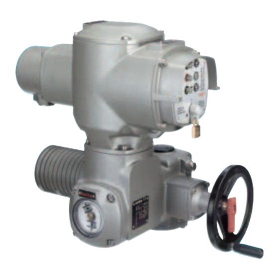
Short description AUMA multi-turn actuators type SA 07.1 – SA 16.1 have a modular design. The actuators are driven by an electric motor and controlled with the electro-mechanical version of the controls AUMA MATIC BASIC AMB 01.1/AMB 02.1, which are included in the scope of supply. -
Page 5: Technical Data
Multi-turn actuators SA 07.1 – SA 16.1 Operation instructions with actuator controls AMB 01.1/AMB 02.1 Technical data Table 1: Technical data multi-turn actuator SA 07.1 – SA 16.1 Features and functions Type of duty Standard: Short-time duty S2 - 15 min. - Page 6 Multi-turn actuators SA 07.1 – SA 16.1 with actuator controls AMB 01.1/AMB 02.1 Operation instructions Other information EC directives Electromagnetic Compatibility (EMC): (89/336/EEC) Low Voltage Directive: (73/23/EEC) Machinery Directive: (98/37/EC) Reference documents Product description “Electric multi-turn actuators SA” Dimension sheets SA...
-
Page 7: Additional Information To The Wiring Diagram Legend
Multi-turn actuators SA 07.1 – SA 16.1 Operation instructions with actuator controls AMB 01.1/AMB 02.1 Additional information to the wiring diagram legend Information A: Change-over switch S9 for changing the type of seating (see subclause 19.2, page 23). Information B: Self-retaining in local operation can be cancelled by cutting the link B3 (see subclause 19.3, page 24). -
Page 8: Mounting To Valve/ Gearbox
Multi-turn actuators SA 07.1 – SA 16.1 with actuator controls AMB 01.1/AMB 02.1 Operation instructions Mounting to valve/ gearbox Prior to mounting the actuator must be checked for damage. Damaged parts must be replaced by original spare parts. After mounting to valve/ gearbox, touch up any possible damage to paint finish. - Page 9 Multi-turn actuators SA 07.1 – SA 16.1 Operation instructions with actuator controls AMB 01.1/AMB 02.1 Finish machining of stem nut (output drive type A): Figure B-1 Output drive type A Stem nut 80.3 80.01/ 80.02 80.2 The output drive flange does not have to be removed from the actuator.
-
Page 10: Manual Operation
Multi-turn actuators SA 07.1 – SA 16.1 with actuator controls AMB 01.1/AMB 02.1 Operation instructions Manual operation The actuator may be operated manually for purposes of setting and commissioning, and in case of motor failure or power failure. Manual operation is engaged by an internal change-over mechanism. -
Page 11: Electrical Connection
51.01 instructions. In case the wiring diagram is not available, it can be obtained from AUMA (state commission no., refer to name plate) or downloaded directly from the Internet (www.auma.com). Bild G-2: Parking frame (accessory) A special parking frame (figure G-2) for protection against touching the bare contacts and against environmental influences is available. -
Page 12: Heater
Multi-turn actuators SA 07.1 – SA 16.1 with actuator controls AMB 01.1/AMB 02.1 Operation instructions Heater AUMA multi-turn actuators have a heater installed as standard. To prevent condensation, the heater must be connected. Motor protection In order to protect against overheating and impermissibly high temperatures at the actuator, thermoswitches are embedded in the motor winding. -
Page 13: Opening The Switch Compartment
Multi-turn actuators SA 07.1 – SA 16.1 Operation instructions with actuator controls AMB 01.1/AMB 02.1 10. Opening the switch To be able to make the following settings (clause 11. to 17.) the switch compartment compartment must be opened and, if installed, the indicator disc must be removed. -
Page 14: Setting Of The Limit Switching
Multi-turn actuators SA 07.1 – SA 16.1 with actuator controls AMB 01.1/AMB 02.1 Operation instructions 11. Setting of the limit switching 11.1 Setting for end position CLOSED (black section) Turn handwheel clockwise until valve is closed. After having reached the end position, turn back handwheel approximately 1/2 a turn (overrun). -
Page 15: Setting Of The Duo Limit Switching (Option)
Multi-turn actuators SA 07.1 – SA 16.1 Operation instructions with actuator controls AMB 01.1/AMB 02.1 12. Setting of the DUO limit switching (option) Any application can be switched on or off via the two intermediate position switches. For setting, the switching point (intermediate position) must be approached from the same direction as afterwards in electrical operation. -
Page 16: Setting Of The Torque Switching
Multi-turn actuators SA 07.1 – SA 16.1 with actuator controls AMB 01.1/AMB 02.1 Operation instructions 13. Setting of the torque switching 13.1 Setting The set torque must suit the valve! This setting should only be changed with the consent of... -
Page 17: Test Run
Multi-turn actuators SA 07.1 – SA 16.1 Operation instructions with actuator controls AMB 01.1/AMB 02.1 14. Test run 14.1 Check direction of rotation This check is only required for multi-turn actuators with 3-ph AC motor. If provided, place indicator disc on shaft. -
Page 18: Check The Setting Of The Limit Switching
Multi-turn actuators SA 07.1 – SA 16.1 with actuator controls AMB 01.1/AMB 02.1 Operation instructions 14.2 Check the setting of the limit switching Move actuator manually into both end positions of the valve. Check whether limit switching is set correctly. Hereby observe that the appropriate switch is tripped in each end position and released again after the direction of rotation is changed. -
Page 19: Setting Of Electronic Position Transmitter Rwg (Option)
Multi-turn actuators SA 07.1 – SA 16.1 Operation instructions with actuator controls AMB 01.1/AMB 02.1 16. Setting of electronic position transmitter RWG (option) – For remote indication or external control – After mounting the multi-turn actuator to the valve, check setting by measuring the output current (see subclause 16.1 or 16.2) and re-adjust, if... -
Page 20: Setting For 2-Wire System 4 - 20 Ma And 3- /4-Wire System 0 - 20 Ma
Multi-turn actuators SA 07.1 – SA 16.1 with actuator controls AMB 01.1/AMB 02.1 Operation instructions 16.1 Setting for 2-wire system 4 – 20 mA and 3- /4-wire system 0 – 20 mA Connect voltage for electronic position transmitter. Move valve to end position CLOSED. -
Page 21: Setting For 3- / 4- Wire System 4 - 20 Ma
Multi-turn actuators SA 07.1 – SA 16.1 Operation instructions with actuator controls AMB 01.1/AMB 02.1 16.2 Setting for 3- / 4- wire system 4 – 20 mA Connect voltage for electronic position transmitter. Move valve to end position CLOSED. If installed, pull off indicator disc. -
Page 22: Setting Of The Mechanical Position Indicator (Option)
Multi-turn actuators SA 07.1 – SA 16.1 with actuator controls AMB 01.1/AMB 02.1 Operation instructions 17. Setting of the mechanical position indicator (option) A suitable reduction gearing was installed in our works. If the turns per stroke are changed at a later date, the reduction gearing may have to be exchanged, too. -
Page 23: Controls Auma Matic Basic
Multi-turn actuators SA 07.1 – SA 16.1 Operation instructions with actuator controls AMB 01.1/AMB 02.1 19. Controls AUMA MATIC BASIC 19.1 Removal of the local controls The local controls must only be removed when settings at the controls have to be performed (subclause 19.2 to 19.4). -
Page 24: Push-To-Run Operation Or Self-Retaining In Selector Switch Position Local
Multi-turn actuators SA 07.1 – SA 16.1 with actuator controls AMB 01.1/AMB 02.1 Operation instructions 19.3 Push-to-run operation or self-retaining in selector switch position LOCAL Push-to-run operation or self-retaining is set in the factory. A change at a later date is only possible by cutting the link B3 (see figure R-2). -
Page 25: Settings On Relay Board For Potential-Free Feedback (Option)
Figure T2: Relay board version B04 Plug-in links Remove cover (figure R-1, page 23) of AUMA MATIC BASIC. Assign the required functions to the terminals XK ... of the customer connection (see wiring diagram) with the red plug-in links, according to table 8. -
Page 26: Fuses
Multi-turn actuators SA 07.1 – SA 16.1 with actuator controls AMB 01.1/AMB 02.1 Operation instructions 20. Fuses Fuses (figures U1 and U2) are accessible after removal of the local controls (refer to page 23, figure R-1). When exchanging the fuses, only fuses with the same values must be used. -
Page 27: Maintenance
Lubrication of the valve stem must be done separately. 23. Disposal and recycling AUMA actuators have an extremely long lifetime. However, there will come a time when you have to replace them. Our actuators have a modular design and may therefore easily be disassembled, separated and sorted according to materials, i.e.:... - Page 28 Multi-turn actuators SA 07.1 – SA 16.1 with actuator controls AMB 01.1/AMB 02.1 Operation instructions Notes...
- Page 29 Multi-turn actuators SA 07.1 – SA 16.1 Operation instructions with actuator controls AMB 01.1/AMB 02.1 Notes...
-
Page 30: Spare Parts List Multi-Turn Actuator Sa 07.1 - Sa
Multi-turn actuators SA 07.1 – SA 16.1 with actuator controls AMB 01.1/AMB 02.1 Operation instructions 25. Spare parts list multi-turn actuator SA 07.1 – SA 16.1... - Page 31 Multi-turn actuators SA 07.1 – SA 16.1 Operation instructions with actuator controls AMB 01.1/AMB 02.1 Note: When placing orders for spare parts, please mention type of actuator and our commission number (refer to name plate). Type Designation Type Designation Notched pin 58.0...
-
Page 32: Spare Parts List Controls Auma Matic
Multi-turn actuators SA 07.1 – SA 16.1 with actuator controls AMB 01.1/AMB 02.1 Operation instructions 26. Spare parts list controls AUMA MATIC... - Page 33 Multi-turn actuators SA 07.1 – SA 16.1 Operation instructions with actuator controls AMB 01.1/AMB 02.1 Note: When placing your order for spare parts, please mention type of the controls and our commission number (refer to name plate of controls). Type...
-
Page 34: Declaration Of Conformity And Declaration Of Incorporation
Multi-turn actuators SA 07.1 – SA 16.1 with actuator controls AMB 01.1/AMB 02.1 Operation instructions 27. Declaration of Conformity and Declaration of Incorporation... -
Page 35: Index
Multi-turn actuators SA 07.1 – SA 16.1 Operation instructions with actuator controls AMB 01.1/AMB 02.1 Index Control voltage Limit switches Safety instructions Corrosion protection 7,27 Limit switching 14,15,18 Self-retaining Local controls 6,23 Service Lubrication Signal and control board Declaration of Conformity... -
Page 36: Addresses Of Auma Offices And Representatives
Certificate Registration No. +49 (0)7631/809-0 +49 (0)711 / 34803 0 12 100 4269 +49 (0)7631/809 250 +49 (0)711 / 34803 34 12 104 4269 riester@auma.com riester@wof.auma.com www.auma.com www.auma.com For detailed information about the AUMA products refer to the Internet: Y000.586/003/en/1.04 www.auma.com...
Need help?
Do you have a question about the SA 07.1 and is the answer not in the manual?
Questions and answers