Table of Contents
Advertisement
Advertisement
Table of Contents

Related Manuals for Prins VSI LPG


Summary of Contents for Prins VSI LPG
- Page 1 DATE : 2013-09-04 Copyright © Prins Autogassystemen B.V. 2013 VERSION NR :...
-
Page 2: Table Of Contents
Electrical connections Dual Sensor Interface (DSI) ________________________________________ 32 Electrical connections CNG Prins Timing Optimizer (PTO) _________________________________ 33 Diagram CNG PTO wiring Prins Turbo / MAP sensor ______________________________________ 33 Prins Turbo / MAP sensor _____________________________________________________________ 34 Diagram 5 LPG Base layout VSI 4 cylinder connector ____________________________________ 35... - Page 3 Diagram 37 LPG wiring 080/72065 ____________________________________________________ 70 Diagram 38 CNG wiring 095/72045 ____________________________________________________ 71 Diagram 39 VSI-2.0 wiring 191/040002 _________________________________________________ 72 Trouble code chart LPG ______________________________________________________________ 73 Maintenance instructions _____________________________________________________________ 74 Checklist after installation ____________________________________________________________ 76 Copyright © Prins Autogassystemen B.V. 2013 Page 2...
-
Page 4: Required Equipment / Tools / Materials For Installing A Complete System
Com port : 1 free COM port 1 or COM port 2 with a 9 or 25 pins connector or USB Vehicle fuel system scan tool or OBD scan tool Prins ( part nr. 099/99928 ) Exhaust gas analyser Multimeter... -
Page 5: General Instructions
Fitting and maintenance is only allowed by Prins Autogassystemen selected LPG/CNG engineers. Prins Autogassystemen is not responsible for any damages to people or objects as a result of changes to Prins products. Check our website regularly for updates, info-bulletins and product information. -
Page 6: Introduction
This achieves a much higher level of performance emission and drivability. The VSI system was designed and developed in-house by Prins Autogassystemen B.V. VSI characterizes itself with a high level of integration into to the petrol management system. The two systems integrate as “master-slave”... -
Page 7: Approval Numbers Vsi Lpg / Cng Components
Approval numbers VSI LPG / CNG components Mark Component Prins VSI Reducer E4-67R-010054 Valtec 6 / 8mm lock-off valve E4-67R-010041 Keihin Regulator E4-110R-000092 lock-off valve E4-110R-000095 Wika CNG Pressure indicator E4-110R-000190 Prins VSI Injector rail E4-67R-010093 E4-110R-000021 Keihin VSI Injector... -
Page 8: The Prins Lpg Reducer
The Prins LPG reducer Mount the reducer to the body of the vehicle in the engine compartment, never on the engine! Mount the reducer so that it is easy to adjust the pressure. Install the supplied 8 mm threaded end in the back cover of the reducer. -
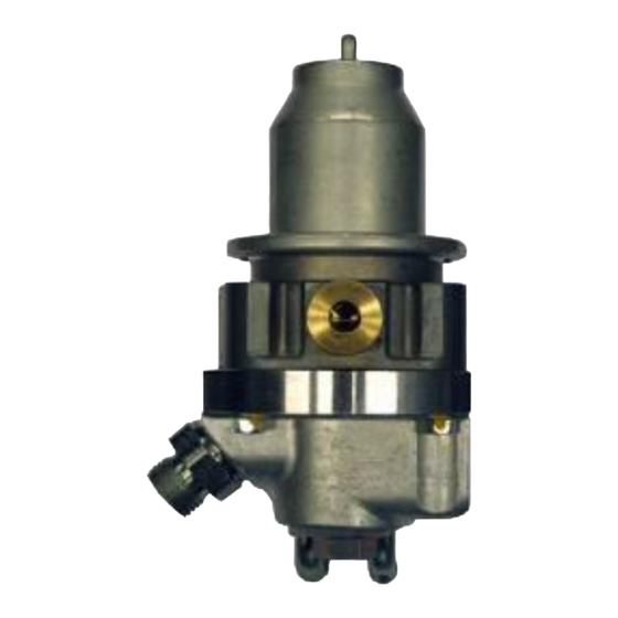
Page 9: The Keihin Cng Regulator
No component of the CNG-system shall be located within 100 mm of the exhaust or similar heat source, unless such components are adequately shielded against heat. The pressure may not be adjusted and is fixed on 3.3 bar Copyright © Prins Autogassystemen B.V. 2013 Page 8... -
Page 10: The Injector Rail
The injector rail VSI 4-cylinder injector rail [KN8/KN9] The Prins injector rail is available in 2 - 3 - 4 - 5 rail versions. Guideline VSI injector choice : divide total engine power in kW up into the amount of cylinders. -
Page 11: The Prins Filter Unit
The Prins filter unit The filter unit filters the LPG/CNG and is also used to measure the gas temperature (T_gas) and gas pressure (Psys) in the VSI system, by means of a combination sensor. The filter unit has a single or a double outlet of 11mm. -
Page 12: The Vsi Computer
The VSI computer can be mounted into the engine room as well as inside the car, depending on the converted vehicle. Never mount the computer near a heat source. Never mount the computer upside down. Never clean engine room with a high pressure cleaner. VSI-I Copyright © Prins Autogassystemen B.V. 2013 Page 11... -
Page 13: Vsi-2.0 Computer
VSI-2.0 computer The Prins VSI-2.0 computer is the second generation master-slave management system. This new design has distinctive features and will be used as a new platform for current and future Prins injection systems. Copyright © Prins Autogassystemen B.V. 2013... -
Page 14: Instructions Rotating The Prins Vsi Injector Rail
Instructions rotating the Prins VSI injector rail This is an instruction how to convert a “right” rail into a “left” injector rail Tools : Ring spanner size 13 mm Torque spanner ( 0-3 Nm ) Disassembly / assembly: 1. Unscrew both M8 (4) nuts. -
Page 15: The Wiring Loom
VSI computer. VSI-2.0 The wiring harness connects to the computer via two Bosch a 81+40 pins connector which is locked to the VSI-2.0 computer by means of connector clamping mechanism. Copyright © Prins Autogassystemen B.V. 2013 Page 14... -
Page 16: Hose Connections
Try to keep the inlet manifold hoses as short as possible. Use a hose clamp on all the LPG/CNG hose connections. Please observe that there is no damage or fouling to the hoses. Copyright © Prins Autogassystemen B.V. 2013 Page 15... -
Page 17: Diagram 1 Vsi Inlet Manifold Coupling
VSI injector VSI inlet manifold coupling petrol injector Hose clamp LPG hose inlet manifold exhaust manifold Hose clamp Coupling Lambda sensor Diagram 1 VSI inlet manifold coupling... -
Page 18: Diagram 2 Vsi Inlet Manifold Coupling With Nylon Hose
VSI inlet manifold coupling with nylon hose VSI injector petrol injector Hose clamp LPG hose Hose clamp inlet manifold exhaust manifold Nylon hose Barrel Coupling oxygen sensor Diagram 2 VSI inlet manifold coupling with nylon hose Copyright © Prins Autogassystemen B.V. 2013 Page 17... -
Page 19: Diagram 3 Parallel Water Connection
1 reducer vsi coupling lock-off valve inlet manifold throttle body LPG fuel line Tank exhaust heater interior heater with valve valve engine coolant T-piece oxygen sensor Diagram 3 Parallel water connection Copyright © Prins Autogassystemen B.V. 2013 Page 18... -
Page 20: Diagram 4 Serial Water Connection
1 reducer vsi coupling lock-off valve inlet manifold throttle body LPG fuel line Tank exhaust interior heater without valve engine coolant oxygen sensor Diagram 4 Serial water connection Copyright © Prins Autogassystemen B.V. 2013 Page 19... -
Page 21: Diagram 5 Serial Water Connection Cng Regulator
Diagram 5 Serial water connection CNG regulator Copyright © Prins Autogassystemen B.V. 2013 Page 20... -
Page 22: The Vsi-I Fuel Switch
The VSI-I fuel switch Mount the switch on a visible and approachable place for the driver. When mounting the switch, only push on its sides. Pushing the switch in the centre may result in damage to the switch. ELECTRICAL CONNECTION OF THE LPG SWITCH with loose beeper VSI SWITCH POWER FEEDS (51) partnr. -
Page 23: The Vsi-2.0 Fuel Switch
1,0Hz Tank empty, petrol mode Petrol Petrol Led1 on Critical fault Petrol flashing On, 2Hz 1,0 Hz Non critical fault, petrol mode Petrol Petrol Non critical fault, gas mode Flashing 1,0 Hz Copyright © Prins Autogassystemen B.V. 2013 Page 22... -
Page 24: Electrical Connections On The Lpg Reservoir
TRIPLE WIRE CABLE VSI COMPUTER FITTING BOX COIL Tank gauge TANK VALVE 0-95 Ohm BLACK GREEN BLACK BLACK BLUE SOLDER THE CONNECTIONS IN THE FITTING BOX AND PROTECT THEM WITH A SHRINK SLEEVE. Copyright © Prins Autogassystemen B.V. 2013 Page 23... -
Page 25: Electrical Connections Vsi-I Wiring Harness
For interrupting the crank signal on CNG. yellow Ground blue For measuring the high pressure signal of the CNG system + CNG green-yellow In combination with Prins High Pressure gauge Signal blue Copyright © Prins Autogassystemen B.V. 2013 Page 24... -
Page 26: Electrical Connections Vsi-I Wiring Harness
Light blue-yellow vsi nr. 09 ( petrol injector cyl.7 ) =>VSI-ecm=> Light blue-yellow vsi nr.03 ( vsi injector cyl.7 ) Red-yellow vsi nr. 08 ( petrol injector cyl.8 ) =>VSI-ecm=> Red-yellow vsi nr.02 ( vsi injector cyl.8 ) Copyright © Prins Autogassystemen B.V. 2013 Page 25... -
Page 27: Electrical Connections Vsi-2.0 Wiring Harness
Wire colour : Wire location : AD2 ( Valve Care ) green Optional connection. Wire colour : Wire location : purple-white For measuring the engine speed. Wire colour : Wire location : Copyright © Prins Autogassystemen B.V. 2013 Page 26... -
Page 28: Electrical Connections Vsi-2.0 Wiring Harness
For measuring the inlet manifold pressure ( Prins MAP sensor AD1 ( MAP ) blue +5 volt sensor brown Connect the 3-pole connector to the Prins MAP sensor. C ground 2-pole blue connector For measuring the engine coolant temperature ( Tect ). Tect grey... -
Page 29: Electrical Connections Vsi-2.0 Wiring Harness
Connect to the second tank lock-off valve. ground switched 1 brown Optional / insulate 3-pole connector + manometer Connect to the CNG high pressure gauge tank level in blue Optional / insulate ground manometer brown Copyright © Prins Autogassystemen B.V. 2013 Page 28... -
Page 30: Electrical Connections Vsi-2.0 Wiring Harness
–GAS INJ 2 Connector VSI-injector cylinder 2. green-yellow +GAS INJ 2 –GAS INJ 3 Connector VSI-injector cylinder 3. pink-yellow +GAS INJ 3 –GAS INJ 4 blue-yellow Connector VSI-injector cylinder 4. +GAS INJ 4 Copyright © Prins Autogassystemen B.V. 2013 Page 29... -
Page 31: Electrical Connections Rpm Module 091/0236
Connect the grey-white wire of the RPM module to the grey-white wire nr.13 of the VSI wiring loom. Connect the purple wire of the RPM module to the ignition coil driver wire. Copyright © Prins Autogassystemen B.V. 2013 Page 30... -
Page 32: Electrical Connections Petrol Pressure Simulator 091/0252
Next we have to setup the same Voltage (pressure) when running on LPG via de pot meter. The pot meter is accessible when you remove the small protection cover of the module. Copyright © Prins Autogassystemen B.V. 2013 Page 31... -
Page 33: Electrical Connections Dual Sensor Interface (Dsi)
Connect the interface wiring according to drawing, all blue and black wires are exchangeable since they are internally connected. The DSI makes it possible to connect two level sensors to one lpg switch. The DSI will always show the highest lpg level on the switch. Copyright © Prins Autogassystemen B.V. 2013 Page 32... -
Page 34: Electrical Connections Cng Prins Timing Optimizer (Pto)
Electrical connections CNG Prins Timing Optimizer (PTO) Connect the PTO module according the shown diagram. Check if the latest software is downloaded in the PTO! Diagram CNG PTO wiring Copyright © Prins Autogassystemen B.V. 2013 Page 33... -
Page 35: Prins Turbo / Map Sensor
Prins Turbo / MAP sensor Copyright © Prins Autogassystemen B.V. 2013 Page 34... -
Page 36: Diagram 5 Lpg Base Layout Vsi 4 Cylinder Connector
Diagram 5 LPG Base layout VSI 4 cylinder connector... -
Page 37: Diagram 6 Lpg Base Layout Vsi 4 Cylinder Solder
Diagram 6 LPG Base layout VSI 4 cylinder solder... -
Page 38: Diagram 7 Lpg Base Layout Vsi 5 Cylinder
Diagram 7 LPG Base layout VSI 5 cylinder... -
Page 39: Diagram 8 Lpg Base Layout Vsi 6 Cylinder Connector
Diagram 8 LPG Base layout VSI 6 cylinder connector... -
Page 40: Diagram 9 Lpg Base Layout Vsi 6 Cylinder Solder
Diagram 9 LPG Base layout VSI 6 cylinder solder... -
Page 41: Diagram 10 Lpg Base Layout Vsi 8 Cylinder Connector
Diagram 10 LPG Base layout VSI 8 cylinder connector... -
Page 42: Diagram 11 Lpg Base Layout Vsi 8 Cylinder Solder
Diagram 11 LPG Base layout VSI 8 cylinder solder... -
Page 43: Diagram 12 Cng Base Layout
Diagram 12 CNG Base layout... -
Page 44: Diagram 13 Vsi-2.0 Lpg Base Layout
Diagram 13 VSI-2.0 LPG Base layout... -
Page 45: Diagram 14 Vsi-2.0 Map Lpg Base Layout
Diagram 14 VSI-2.0 MAP LPG Base layout... -
Page 47: Diagram 13 Injection Module 4-Cylinder ( 180/70024 Connector )
4-CYLINDER CONNECTOR INJECTION MODULE VSI 1 REV.B 06-06-2005 blue-yellow 36 ecu side 4 blue min inj side 4 injection module 4 cylinder pink-yellow 37 ecu side 3 180/70024 pink min inj side 3 green-yellow 38 ecu side 2 green min inj side 2 white-yellow 39 ecu side 1 white min inj side 1 PETROL INJECTORS... -
Page 48: Diagram 14 Injection Module 4-Cylinder ( 180/ 70024 Solder )
4-CYLINDER SOLDER INJECTION MODULE VSI 1 REV.B 06-06-2005 petrol ecu blue-yellow 36 ecu side 4 blue min inj side 4 petrol ecu injection module 4 cylinder pink-yellow 37 ecu side 3 180/70024 pink min inj side 3 petrol ecu green-yellow 38 ecu side 2 green min inj side 2 petrol ecu white-yellow 39 ecu side 1... -
Page 49: Diagram 15 Injection Module 6-Cylinder ( 180/70026 Connector )
6-CYLINDER CONNECTOR INJECTION MODULE VSI 1 REV.B 06-06-2005 brown-yellow 10 ecu side 6 brown min inj side 6 grey-yellow 11 ecu side 5 grey min inj side 5 blue-yellow 36 ecu side 4 injection module 6 cylinder blue min inj side 4 180/70026 pink-yellow 37 ecu side 3 pink min inj side 3... -
Page 50: Diagram 16 Injection Module 6-Cylinder ( 180/70026 Solder )
6-CYLINDER SOLDER INJECTION MODULE VSI 1 REV.B 06-06-2005 petrol ecu brown-yellow 10 ecu side 6 brown min inj side 6 petrol ecu grey-yellow 11 ecu side 5 grey min inj side 5 petrol ecu injection module blue-yellow 36 ecu side 4 6 cylinder 180/70026 blue min inj side 4... -
Page 51: Diagram 17 Injection Module 8-Cylinder ( 180/ 70024 Connector)
8-CYLINDER CONNECTOR INJECTION MODULE VSI 1 REV.B 06-06-2005 petrol ecu petrol ecu petrol ecu petrol ecu PETROL INJECTORS white min inj side 1 white-yellow 39 ecu side 1 8 cylinder injection module 180/70024 pink min inj side 3 pink-yellow 37 ecu side 3 grey min inj side 5 grey-yellow 11 ecu side 5 light blue min inj side 7... -
Page 52: Diagram 18 Injection Module 8-Cylinder ( 180/70024 Solder)
8-CYLINDER SOLDER INJECTION MODULE VSI 1 REV.B 06-06-2005 PETROL INJECTORS white min inj side 1 white-yellow 39 ecu side 1 8 cylinder petrol ecu injection module 180/70024 pink min inj side 3 pink-yellow 37 ecu side 3 petrol ecu grey min inj side 5 grey-yellow 11 ecu side 5 petrol ecu light blue min inj side 7... -
Page 53: Diagram 19 Repair Module 180/30024 (4-8 Cylinder)
4 & 8 CYLINDER REPAIR INJECTION MODULE VSI 1 REV.B 180/30024 06-06-2005 injection module REPAIR MODULE wire A B C D 4 cylinder 1 2 3 4 8 cylinder module A 1 3 5 7 8 cylinder module B 2 4 6 8 26 SIMU LOW=ON INJ SIDE A 50 MAIN GROUND... -
Page 54: Diagram 20 Connector Injection Module 091/71004
Diagram 20 connector injection module 091/71004... -
Page 55: Diagram 21 Injection Module 091/71006
Diagram 21 injection module 091/71006... -
Page 56: Diagram 22 Replacing The Injection Module 180/70024 → 091/0145
REPLACING THE INJECTION MODULE VSI 1 REV.B BY OLD TYPE 06-06-2005 petrol ecu petrol ecu white-yellow 39 ecu side 1 blue-yellow 36 ecu side 4 Black white min inj side 1 blue min inj side 4 petrol ecu petrol ecu green-yellow 38 ecu side 2 OLD TYPE NEW TYPE... -
Page 57: Diagram 23 Replacing The Injection Module 180/70024 → 091/71004 (4 Cylinder)
080/71996 A2 A3 A4 A5 A6 A7 C8 B8 B1 = solder insulate Petrol injectors Petrol injectors VSI LPG / CNG ECU VSI LPG / CNG ECU manufacturer : Prins manufacturer : Prins version : version : software :... -
Page 58: Diagram 24 Replacing The Injection Module 180/70026 → 091/71006 (6 Cylinder)
080/71996 A2 A3 A4 A5 A6 A7 C8 B8 B1 solder Petrol injectors Petrol injectors VSI LPG / CNG ECU manufacturer : Prins VSI LPG / CNG ECU version : manufacturer : Prins software : version :... -
Page 59: Diagram 25 Replacing The Injection Module 180/70024 → 091/71004 (8 Cylinder)
Petrol injectors = solder = solder insulate insulate Petrol injectors Petrol injectors 39 38 37 36 VSI LPG / CNG ECU VSI LPG / CNG ECU manufacturer : Prins manufacturer : Prins version : version : software : software :... -
Page 60: Diagram 26 Lpg Wiring 180/70014
1-2-3-4 t° Oxygen sensor 1 Bank 1 Hall sensor engine RPM 39 38 37 36 VSI LPG ECU manufacturer : Prins version : software : 33 32 31 30 43 42 15 18 17 22 23 VSI injectors... -
Page 61: Diagram 27 Lpg Wiring 180/70004
1-2-3-4 t° Oxygen sensor 1 Bank 1 Hall sensor engine RPM Petrol injectors VSI LPG ECU manufacturer : Prins version : software : 33 32 31 43 42 15 18 17 22 23 VSI injectors injector... -
Page 62: Diagram 28 Lpg Wiring 180/70016
Oxygen Oxygen sensor 1 sensor 1 Bank 1 Bank 2 Hall sensor engine RPM VSI LPG ECU manufacturer : Prins version : software : 33 32 31 30 5 43 42 15 18 17 22 23 VSI injectors... -
Page 63: Diagram 29 Lpg Wiring 180/70006
Hall sensor engine RPM Oxygen Oxygen sensor 1 sensor 1 Bank 1 Bank 2 Petrol injectors VSI LPG ECU manufacturer : Prins version : software : 33 32 31 30 5 43 42 15 18 17 22 23 VSI injectors... -
Page 64: Diagram 30 Lpg Wiring 180/70018
1 sensor 1 Bank 1 Bank 2 Hall sensor engine RPM 39 38 37 36 VSI LPG ECU manufacturer : Prins version : software : 33 32 31 30 5 4 3 2 15 18 17 22 23 VSI injectors... -
Page 65: Diagram 31 Lpg Wiring 180/70008
1 sensor 1 Bank 1 Bank 2 Petrol injectors Petrol injectors 39 38 37 36 VSI LPG ECU manufacturer : Prins version : software : 33 32 31 30 5 4 3 2 43 42 15 18 17 22 23... -
Page 66: Diagram 32 Lpg Wiring 080/72040
G INJ OUT 3 pink-yellow orange ignition + grey-white G INJ OUT 2 green-yellow reducer valve brown ground Prins Alternative Fuel Systems vsi ecu red-white 26 inj. mod. command ground black G INJ OUT 1 white-yellow main ground brown Project name :... -
Page 67: Diagram 33 Lpg Wiring 080/72045
G INJ OUT 4 blue-yellow beeper low switching black pulse fuel switch yellow diagnose LED G INJ OUT 3 pink-yellow orange Prins Alternative Fuel Systems ignition + grey-white G INJ OUT 2 green-yellow reducer valve brown Project name : ground vsi ecu red-white 26 inj. -
Page 68: Diagram 34 Lpg Wiring 080/72050
11 ecu side 5 pulse fuel switch yellow G INJ OUT 3 pink-yellow diagnose LED orange Prins Alternative Fuel Systems petrol ecu brown-yellow 10 ecu side 6 ignition + grey-white G INJ OUT 2 green-yellow reducer valve... -
Page 69: Diagram 35 Lpg Wiring 080/72055
11 ecu side 5 pulse fuel switch yellow G INJ OUT 3 pink-yellow diagnose LED orange Prins Alternative Fuel Systems petrol ecu brown-yellow 10 ecu side 6 ignition + grey-white G INJ OUT 2 green-yellow reducer valve... -
Page 70: Diagram 36 Lpg Wiring 080/72060
13 ingnition plus vsi ecu grey-white 13 ingnition plus petrol ecu white-yellow 39 ecu side 1 petrol ecu grey-yellow 11 ecu side 5 Prins Alternative Fuel Systems ignition + grey-white G INJ OUT 2 green-yellow reducer valve ground brown petrol ecu green-yellow... -
Page 71: Diagram 37 Lpg Wiring 080/72065
9 ecu side 7 yellow pulse fuel switch G INJ OUT 3 pink-yellow diagnose LED orange Prins Alternative Fuel Systems petrol ecu blue-yellow 36 ecu side 4 petrol ecu red-yellow 8 ecu side 8 ignition + grey-white... -
Page 72: Diagram 38 Cng Wiring 095/72045
36 ecu side 4 sealed G INJ OUT 4 blue-yellow beeper low switching black pulse fuel switch yellow diagnose LED Prins Alternative Fuel Systems G INJ OUT 3 pink-yellow orange ignition + grey-white Project name : G INJ OUT 2 green-yellow... -
Page 73: Diagram 39 Vsi-2.0 Wiring 191/040002
Diagram 39 VSI-2.0 wiring 191/040002... -
Page 74: Trouble Code Chart Lpg
Adjusted pressure on idle out of range Adjust the idle pressure to the value shown by parameter “ Idle Level “ Programm error during flahing the Check parameter settings, contact Prins Autogassystemen. memory Psys voltage to low Check the ground connection of the Pressure/temperature sensor in the filter unit. -
Page 75: Maintenance Instructions
8Nm Number of kilometres: Number of Number of Number of kilometres: kilometres: kilometres: Date: Date: Date: Date: *The service intervals of the filter replacements may be divergent because of the variable LPG quality. Ask your Prins dealer for more information. - Page 76 Checked for exhaust emissions Number of kilometres: Number of Number of Number of kilometres: kilometres: kilometres: Date: Date: Date: Date: *The service intervals of the filter replacements may be divergent because of the variable CNG quality. Ask your Prins dealer for more information.
-
Page 77: Checklist After Installation
Checklist after installation Connect the serial interface cable and run the VSI diagnosis program. Install the VSI main fuse, and program the fuel switch. Turn the ignition key in the accessory position. When working on the car, beware of moving and rotating parts in the engine compartment. When commissioning the LPG/CNG system, you must activate the VSI computer with the diagnosis software.
Need help?
Do you have a question about the VSI LPG and is the answer not in the manual?
Questions and answers