Table of Contents
Advertisement
Gas & Kamado Combo Grill
Model Number: GR2150901-MM-00
Assembly and Operating Instructions
For Outdoor Use Only
This instruction manual contains important information necessary for the proper
assembly and safe use of this product. Read and follow all warnings and instructions
before assembling and using this product. Failure to follow these instructions and
warnings could result in damage to the product or injury to the user. Keep this
instruction manual for future reference.
Should you encounter any problem,
CALL US FIRST.
DO NOT return product to the retail store!!
WE CAN HELP.
For assistance, contact customer service at
customerservice@rankam.com
or at (888) 837-1380, Mon to Fri, 8:00am – 5:00pm Pacific Standard time
1 of 39
20141119-Ver1
Advertisement
Table of Contents

Related Manuals for Members Mark GR2150901-MM-00


Summary of Contents for Members Mark GR2150901-MM-00
- Page 1 Gas & Kamado Combo Grill Model Number: GR2150901-MM-00 Assembly and Operating Instructions For Outdoor Use Only This instruction manual contains important information necessary for the proper assembly and safe use of this product. Read and follow all warnings and instructions before assembling and using this product.
-
Page 2: Prop 65 Warning
DANGER If you smell gas: 1. Shut off gas to the appliance. 2. Extinguish any open flame. 3. Open lid. 4. If odor continues, keep away from the appliance and immediately call your gas supplier or fire department. Failure to follow these instructions could result in fire or explosion which could cause property damage, personal injury or death. - Page 3 WARNING This outdoor cooking gas appliance shall be used only outdoors and shall not be used in a building, garage or any other enclosed area. This outdoor cooking gas appliance is not intended to be installed in or on boats. This appliance is not intended to be installed in or on recreational vehicles.
-
Page 4: Lp Gas Cylinder
WARNING BEFORE EVERY USAGE: Be sure to inspect the hose for leaks, cuts, wear, abrasion, or damage of any sort before using this appliance. If any damage is apparent the hose must be replaced with a replacement hose specified by the manufacturer before it is put in use. USE OF LP GAS CYLINDER AND INSTALLATION BEFORE INSTALLING: The installation must conform with local codes or, in the absence of local codes, with either the... - Page 5 DANGER DO NOT connect this grill to an existing #510 POL cylinder valve with Left hand threads. The Type 1 valve can be identified with the large external threads on the valve outlet. DO NOT connect to a LP gas cylinder exceeding its capacity. ...
-
Page 6: Installing Gas Cylinder
INSTALLING GAS CYLINDER 1. Check that cylinder valve is closed by turning knob clockwise. 2. Pull out the cylinder holder along the slot. 3. Place cylinder into cylinder holder and tighten the fixing bolt. Place cylinder such that valve opening faces the side burner and so that hose is not kinked/damaged. 4. -
Page 7: Connection Procedures
CONNECTION PROCEDURES Make sure the cylinder valve is closed (turn LP Cylinder Valve valve clockwise until tight). Check cylinder valve to insure it has proper external male threads. Make sure all burner valves are turned OFF. Inspect valve connections, port, and regulator assembly. - Page 8 CAUTION Keep any electrical supply cord and the fuel supply hose away from any heated surfaces. WARNING To protect against electric shock, do not immerse cord or plugs in water or other liquid. Unplug from the outlet when not in use and before cleaning. Allow to cool before putting on or taking off parts.
-
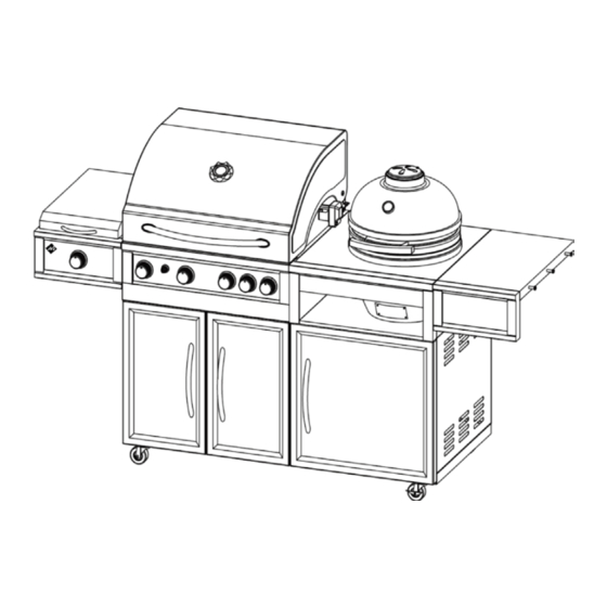
Page 9: Product Diagram
PRODUCT DIAGRAM 9 of 39 20141119-Ver1... -
Page 10: Component List
COMPONENT LIST 1. Warming Rack 2. Cooking Grates 3. Heat Distribution Plates Qty: 1pc Qty: 3pcs Qty: 4pcs 4. Spit Rod Holder (Left) 5. Spit Rod Holder (Right) 6. Rotisserie Spit Rod Qty: 1pc Qty: 1pc Qty: 1pc 7. Forks 8. - Page 11 13. Burner Control Knob 14.Grease Cups 15. Grill Body assembly Qty: 1pc Qty: 2pcs Qty: 1pc 16. Right Side Table 17. Right Side Table Panel 18. Ceramic Grill Body Assembly Qty: 1pc Qty: 1pc Qty: 1pc 18-1. Ceramic Grill Top Vent 18-2.
-
Page 12: Hardware List
HARDWARE LIST Item No. Item name Diagram LR6/AA Battery 1 pc Screwdriver 1 pc M6x10 mm Bolt 12 pcs M6x30 mm Bolt 2 pcs M4x8 mm Bolt 4 pcs M4x35 mm Bolt 2 pcs M4x10 mm Bolt 5 pcs Note: Hardware C,D,E,F and G have been pre-attached on the components. 12 of 39 20141119-Ver1... - Page 13 Replacement Part List (I) 16-1 15-30 13 of 39 20141119-Ver1...
- Page 14 Replacement Part List (II) Part Part Name Part Part Name Number Number Warming Rack Cooking Grates Heat Distribution Plates Spit Rod Holder (Left) Spit Rod Holder (Right) Rotisserie Spit Rod Forks Collar Side Burner Cooking Grate Side Burner assembly 10-1 Side Burner Lid 10-2 Side Burner Hinge...
-
Page 15: Assembly Procedures
ASSEMBLY PROCEDURES Step 1 Lock all three locking casters to prevent the unit from moving as shown below. When move the grill, unlock all three locking casters and action at the right side panel. Step 2 Loosen 2 pcs pre-attached bolts M6X10 (C) from the Grill Body assembly (15) left panel and remove 2 pcs pre-attached bolts M6X30 (D) from the side burner assembly (10). - Page 16 Step 3. Attach side burner assembly to firebox left side panel by using 2 pcs bolts removing from side burner assembly just now. Then tighten the bolts. Step 4 Secure the ignition wire to the electrode on the side burner assembly. 16 of 39 20141119-Ver1...
- Page 17 Step 5 1. Remove 2 pcs pre-attached bolts M4X8 (E) from side burner valve; 2. Remove one pre-attached bolt M6X10 (C) from main burner control panel; 3. Remove one pre-attached bolt M6X10 (C) and 2 pcs pre-attached bolts M4X35 (F) from the Side Burner Front Panel (11). Step 6 Insert the side burner valve assembly through the hole in the Side Burner Front Panel (11).
- Page 18 Step 7 Firmly seat the valve nozzle into the burner venture. Make sure the Valve outlet (orifice) is inserted STRAIGHTLY into the burner tube as shown. Attach side burner front panel to side burner assembly and main burner control panel by using the removed bolts then tighten the bolts. 18 of 39 20141119-Ver1...
- Page 19 Step 8 Remove 2 pcs pre-attached bolts M4X8 (E) from the Side Burner Lid Handle (20). Attach the handle to the side burner lid by using the removed bolts then tighten the bolts. Step 9 Insert the Control Knob (13) onto the pin coming from the valve. Apply firm pressure to secure the knob.
- Page 20 Step 10 1. Remove 3 pcs pre-attached bolts M6X10 (C) from the Right Side Front Panel (17); 2. Attached the right side front panel to the Right Side Table (16) by using the removed bolts then tighten the bolts. 20 of 39 20141119-Ver1...
- Page 21 Step 11 1. Loosen 4 pcs pre-attached bolts M6X10 (C) from right side panel; 2. Remove one pre-attached bolt M6X10 (C) from main burner control panel. Attached the right table unit to the Grill Body Assembly (15) by placing keyholes over the pre-attached bolts, slide up into place and tighten securely.
- Page 22 Step 12 Remove 4 pcs pre-attached bolts M4X10 (G) from the grill body back panel; Attached the Spit Rod Holders (4,5) to the grill body back panel by using the removed bolts then tighten the bolts. 22 of 39 20141119-Ver1...
- Page 23 Step 13 Attach the Forks (7) and the Collar (8) to the Rotisserie Spit Rod (6) as shown. Make sure that the collar is positioned at the flat end of the spit rod. Put the unit assembly on spit rod holders when not in use. Step 14 Place the Heat Distribution Plates (3), Cooking Grates (2), Warming Rack (1) accordingly and the Side Burner Cooking Grate (9) as shown.
- Page 24 Step 15 Place the Ceramic Grill Fire Bowl (18-4), Ceramic Grill Charcoal Grate (18-3) and the Ceramic Grill Cooking Grate (18-2) accordingly into the Ceramic grill body as shown. The opening of ceramic fire bowl should be aligned with the vent hole of ceramic grill. Attach the Ceramic Grill Top Vent (18-1) to the Ceramic Grill Body Assembly (18) as shown.
- Page 25 Step 16 Place the Grease Cups (14) on the grease cup brackets under the main burner and side burner as shown. Step 17 Install the included LR6/AA Battery (A) into the igniter as shown. 25 of 39 20141119-Ver1...
- Page 26 Step 18 Attach the Motor (19) into the motor bracket along the slot. Remove the power plug holder and the fixing bolt M4X10 (G) on the ceramic grill back panel. Fix the power plug by using the removed holder and bolt. 26 of 39 20141119-Ver1...
- Page 27 Step 19 Insert the pointed end of rotisserie spit rod with the forks into the motor. Place the collar on the bracket and adjust it at the flat end of rotisserie spit rod as shown. Step 20. Your “Gas & Kamado Combo Grill” is now fully assembled. Be sure to carefully and fully review the Instruction Manual before using this appliance.
-
Page 28: Before Testing
LEAK TEST GENERAL Although all gas connections on the grill are leak tested at the factory prior to shipment, a complete gas tightness check must be performed at the installation site due to possible mishandling in shipment, or excessive pressure unknowingly being applied to the unit. Periodically check the entire system for leaks following the procedures listed below. -
Page 29: Lighting Instructions
3. If a leak is present, immediately turn off the gas supply and tighten the leaky fittings. 4. Turn the gas back on and recheck. 5. Should gas continue to leak from any of the fittings, turn off the gas supply and contact customer service at (888) 837-1380 LIGHTING INSTRUCTIONS BEFORE LIGHTING... - Page 30 LIGHTING THE MAIN BURNER AND SIDE BURNER OF GRILL Read instructions before lighting. Open lid before lighting burner. Make sure all control knobs are in the "OFF" position. Turn ON gas valve from source or tank. Push and turn any main burner or side burner control knob to "HI" and immediately press and hold the electronic ignition button.
- Page 31 LIGHTING THE BACK BURNER 1. Read instructions before lighting; 2. Open lid before lighting burner. 3. Make sure all control knobs are in the "OFF" position. 4. Turn ON gas valve from source or tank. 5. Push and turn back burner control knob to "HI", Keep pushing the control knob and immediately press and hold the electronic ignition button.
- Page 32 USING MATCH HOLDER TO LIGHT MAIN BURNER, SIDE BURNER AND BACK ROTISSERIE BURNER Turn OFF all burner valves. Make sure the lid is open. Clip a lighted match on one end of the match holder and hold next to the burner. Turn the control knob(s) to the “HI”...
-
Page 33: Maintenance And Cleaning Instructions
DANGER Keep your face and hands as far away from the grill as possible when lighting it. FLAME CHARACTERISTICS This procedure outlines how to check for proper burner flame characteristics. Burner flames should be blue and stable with little yellow tips, with no excessive noise, or lifting. -
Page 34: Grill Burners
GRILL BURNERS Extreme care should be taken when removing a burner as it must be correctly centered on the orifice before any attempt is made to re-light the grill. Frequency of cleaning will depend on how often you use the grill. Spiders and small insects occasionally spin webs or make nests in the grill burner tubes during transit and warehousing. -
Page 35: To Reinstall The Main Burners
TO REINSTALL THE MAIN BURNERS: 1. Insert the burner into the burner valve. 2. Firmly seat the valve orifice into the burner tube. Make sure the Valve orifice is inserted STRAIGHTLY into the burner tube. If not, lighting the burner may cause explosion and/or fire resulting in serious bodily injury and/or property damage. -
Page 36: Operating The Ceramic Grill
SIDE BURNER REPLACEMENT 1. Remove two burner fixing screws and one side burner electrode fixing screw as shown below. 2. Remove the side burner as shown below. OPERATING THE CERAMIC GRILL For the lighting instructions of the ceramic grill, please refer to the Vision manual included in the box. -
Page 37: After-Use Safety
AFTER-USE SAFETY WARNING Always allow grill and all components to cool completely before handling. Never leave coals and ashes in grill unattended. Make sure coals and ashes are completely extinguished before removing. Before grill can be left unattended, remaining coals and ashes must be removed from grill. -
Page 38: Troubleshooting
TROUBLE SHOOTING Problem: Possible Causes: Main Burner cannot light 1. Check LP cylinder fuel level 2. Bad electrode spark. Check to see if the grill will match light. Electrode or collector may need adjustment. 3. Burner tube may be improperly seated into the burner valve. Reinstall burners referring to section “To reinstall the main burners”. -
Page 39: Limited Warranty
LIMITED WARRANTY Manufacturer warrants this Product to be free from defects in workmanship and materials for a period of Ninety (90) days from the date of purchase, PROVIDED claims are submitted, in writing, with proof of purchase. If any part of this item fails because of a manufacturing defect within the Limited Warranty Period, Manufacturer offers to replace such part(s) provide that such parts have not been improperly repaired, altered, or tampered with or subject to misuse, abuse or exposed to corrosive conditions.
Need help?
Do you have a question about the GR2150901-MM-00 and is the answer not in the manual?
Questions and answers