Table of Contents
Advertisement
CESSNA Model 510 Structural Repair Manual (Rev 2) EXTRACT
Chapter 51 Standard Practices – Structures
•
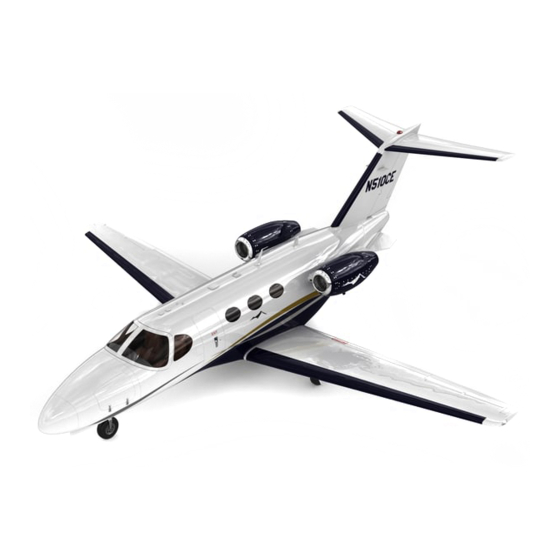
Cessna 510 Mustang (PW 615)
THIS STRUCTURAL REPAIR TRAINING MANUAL HAS BEEN PRODUCED AS AN INSTRUCTION AID
IN SUPPORT OF TECHNICAL GROUND INSTRUCTION. NO AMENDMENTS ARE PROVIDED AFTER
ISSUE. THEY SHOULD ONLY BE USED AS A STUDY GUIDE. THE NOTES MAY NOT BE USED FOR
PLEASE REFER TO THE MANUFACTURERS OFFICIAL
THE PURPOSE OF AIRCRAFT MAINTENANCE:
PUBLICATIONS.
FOR TRAINING USE ONLY
ISSUE 02 , JAN 2018
FOR TRAINING PURPOSES ONLY
Advertisement
Table of Contents

Related Manuals for Cessna 510 Mustang


Summary of Contents for Cessna 510 Mustang
- Page 1 CESSNA Model 510 Structural Repair Manual (Rev 2) EXTRACT Chapter 51 Standard Practices – Structures • Cessna 510 Mustang (PW 615) THIS STRUCTURAL REPAIR TRAINING MANUAL HAS BEEN PRODUCED AS AN INSTRUCTION AID IN SUPPORT OF TECHNICAL GROUND INSTRUCTION. NO AMENDMENTS ARE PROVIDED AFTER ISSUE.
-
Page 2: Table Of Contents
CONTENT: • 51-00-00 - STRUCTURES 51-00-01 - PRINCIPAL STRUCTURAL ELEMENTS 51-00-02 - STRUCTURAL IDENTIFICATION AND DIMENSIONS 51-00-03 - AERODYNAMIC SURFACES 51-01-00 - MAJOR STRUCTURAL DAMAGE REPORT AND REPAIR REQUESTS 51-10-01 - CRACK, SCRATCH, GOUGE AND CORROSION 51-20-01 - PROTECTIVE TREATMENT OF METAL 51-30-01 - SHEET METAL MATERIALS 51-40-03 - FASTENER INSTALLATION AND REMOVAL 51-40-04 - FASTENER SUBSTITUTION... -
Page 3: Structures
Model 510 Structural Repair Manual (Rev 2) 51-00-00-0 (Original Issue) STRUCTURES General Chapter 51 describes general repair practices, materials and procedures which are applicable throughout the subsequent chapters. General information included in Chapter 51 will help when doing the repairs. FOR TRAINING PURPOSES ONLY Copyright ©... -
Page 4: Principal Structural Elements
Model 510 Structural Repair Manual (Rev 2) 51-00-01-0 (Original Issue) PRINCIPAL STRUCTURAL ELEMENTS General The Mustang is certified to the Damage Tolerance and Fatigue requirements. PSE's are defined as, “Those elements which contribute significantly to carrying flight, ground, and pressurization loads, and whose failure could result in catastrophic failure of the airplane.”... - Page 5 Model 510 Structural Repair Manual (Rev 2) 51-00-01-0 (Original Issue) Landing Gear All structural elements of main gear and nose landing gear FOR TRAINING PURPOSES ONLY Copyright © Textron Aviation Inc. Page 2 of 2 Print Date: Wed Mar 21 05:09:44 CDT 2018 Retain printed data for historical reference only.
-
Page 6: Structural Identification And Dimensions
Model 510 Structural Repair Manual (Rev 2) 51-00-02-0 (Original Issue) STRUCTURAL IDENTIFICATION AND DIMENSIONS General This section provides identification and locations of major assemblies, station identification and principal dimensions (Refer to Figure 1, Figure 2, Figure 3, and Figure 4). Abbreviations and Terminology FS - Fuselage Station is a vertical reference plane measured perpendicular to the airplane longitudinal axis,... - Page 7 Model 510 Structural Repair Manual (Rev 2) 51-00-02-0 (Original Issue) Figure 1 : Sheet 1 : Major Assembly Breakdown A60933 Radome Nose Cabin Entry Door Wing Assembly Emergency Exit Speed Brake Speed Brake Flap Flap Aileron Aileron Aileron Trim Tab Nacelle Assembly Pylon Assembly Vertical Stabilizer...
- Page 8 Model 510 Structural Repair Manual (Rev 2) 51-00-02-0 (Original Issue) Figure 1 : Sheet 2 : Major Assembly Breakdown A60934 Horizontal Stabilizer Pylon Vertical Stabilizer Nacelle Wing Vertical Stabilizer Nacelle Rudder Rudder Trim Tab Strake 7010T1002 FOR TRAINING PURPOSES ONLY Copyright ©...
- Page 9 Model 510 Structural Repair Manual (Rev 2) 51-00-02-0 (Original Issue) Figure 2 : Sheet 1 : Major Structural Members Location A60935 Forward Engine Beam Centerline FS 362.750 Aft Engine Beam Centerline Forward FS 380.35 Pressure Pressure (TCS 151.35) Bulkhead Bulkhead FS 144.000 FS 321.000 Engine Forward...
- Page 10 Model 510 Structural Repair Manual (Rev 2) 51-00-02-0 (Original Issue) Figure 3 : Sheet 1 : Station Diagram A60936 WL 192.71 WL 177.220 WL 157.045 WL 130.078 WL 121.870 Instrument Panel Pedestal WL 115.00 Fuselage Water Lines 59.97 inches 1.52 meters 6.00 6.00 6.00...
- Page 11 Model 510 Structural Repair Manual (Rev 2) 51-00-02-0 (Original Issue) Figure 3 : Sheet 2 : Station Diagram A60937 FS 276.000 FS 540.90 FS 276.000 Pressure Pressure Bulkhead Bulkhead FS 144.00 FS 321.00 FS 132.773 FS 249.50 Instrument Panel Pedestal FS 144.00 FS 321.00 Fuselage Stations...
- Page 12 Model 510 Structural Repair Manual (Rev 2) 51-00-02-0 (Original Issue) Figure 3 : Sheet 3 : Station Diagram A60938 0.0 Degrees LBL 47.852 5 Degrees WL 114.682 Trace of FS 362.750 Cut Through Pylon Centerline 3.5 Degrees Side View 7010T1003 FOR TRAINING PURPOSES ONLY Copyright ©...
- Page 13 Model 510 Structural Repair Manual (Rev 2) 51-00-02-0 (Original Issue) Figure 3 : Sheet 4 : Station Diagram A60939 Flap Inboard Edge WS 135.4000 WS 173.500 Flap Hinge Centerline WS 146.00 Flap Hinge Centerline WS 205.500 Flap Hinge Centerline WS 256.610 WS 273.110 WS 349.725 7010T1003...
- Page 14 Model 510 Structural Repair Manual (Rev 2) 51-00-02-0 (Original Issue) Figure 3 : Sheet 5 : Station Diagram A60940 FS 523.305 BL 0.00 BL 26.849 WL 183.965 LBL 98.665 FS 545.249 BL 96.473 FS 245.249 WL 183.965 BL 96.673 Stabilizer Station WL 183.965 7010T1003 FOR TRAINING PURPOSES ONLY...
- Page 15 Model 510 Structural Repair Manual (Rev 2) 51-00-02-0 (Original Issue) Figure 4 : Sheet 1 : Principal Dimensions A60941 17.23 feet 5.25 meters 7010T1002 FOR TRAINING PURPOSES ONLY Copyright © Textron Aviation Inc. Page 10 of 11 Print Date: Wed Mar 21 05:09:46 CDT 2018 Retain printed data for historical reference only.
- Page 16 Model 510 Structural Repair Manual (Rev 2) 51-00-02-0 (Original Issue) Figure 4 : Sheet 2 : Principal Dimensions A60942 43.17 feet 13.16 meters 11.79 feet 3.59 meters 13.45 feet 4.10 meters 14.36 feet 4.38 meters 40.54 feet 12.36 meters 7010T1002 FOR TRAINING PURPOSES ONLY Copyright ©...
-
Page 17: Aerodynamic Surfaces
Model 510 Structural Repair Manual (Rev 2) 51-00-03-0 (Original Issue) AERODYNAMIC SURFACES Loft Contour The loft contour is the outside surface of the skin for the wings, fairings, nacelles, and pylons. The loft contour is the inside surface of the skin for the nose, cockpit, fuselage, and tailcone. C. - Page 18 Model 510 Structural Repair Manual (Rev 2) 51-00-03-0 (Original Issue) Figure 1 : Sheet 1 : Flushness Requirements and Tolerances A63612 Zone 1 Zone 2 Zone 3 FOR TRAINING PURPOSES ONLY Copyright © Textron Aviation Inc. Page 2 of 5 Print Date: Wed Mar 21 05:09:51 CDT 2018 Retain printed data for historical reference only.
- Page 19 Model 510 Structural Repair Manual (Rev 2) 51-00-03-0 (Original Issue) Figure 1 : Sheet 2 : Flushness Requirements and Tolerances A60932 Loft Contour (corrected for norminal skin thickness). 6.00 Inches Actual Contour (152 mm) Maximum Local Deviation (Waviness) Maximum +0.05 or −0.05 Inch (+1.3 or −1.3 mm) from Loft Contour (adjusted for skin thickness) Refer to Table 1.
- Page 20 Model 510 Structural Repair Manual (Rev 2) 51-00-03-0 (Original Issue) Figure 2 : Sheet 1 : Mismatch and Gap FOR TRAINING PURPOSES ONLY Copyright © Textron Aviation Inc. Page 4 of 5 Print Date: Wed Mar 21 05:09:51 CDT 2018 Retain printed data for historical reference only.
- Page 21 Model 510 Structural Repair Manual (Rev 2) 51-00-03-0 (Original Issue) Figure 3 : Sheet 1 : Flushness Requirements and Tolerances A62780 Measure Flushness Fastener Here Measure Fastener Flushness Here Exterior Surface Exterior Surface NOTE 1: Tolerance limits for the lower portions of the wing, fuselage, and tail surfaces are the same as the corresponding upper surfaces.
-
Page 22: Major Structural Damage Report And Repair Requests
To report major structural damage, fill out the Structural Damage Report and Repair Request and the Major Structural Damage Reporting Form. Forward both forms to Cessna Citation Customer Support with the provided Structural Damage Report Fax Cover Page. These reporting forms are for use only for major damage that is either not addressed, or is beyond that covered, in the Model 510 Structural Repair Manual. - Page 23 Make sure molds fully encompass damage area(s) and details such as nearest adjacent fasteners, holes, edges and radii. Obtain required dimensions from molds. Retain molds for possible shipment to Cessna. (6) If damage encompasses a large area, include dimensions on contour maps.
- Page 24 Model 510 Structural Repair Manual (Rev 2) 51-01-00-0 (Original Issue) A17603 STRUCTURAL DAMAGE REPO RT FAX COVER PAGE Today’s Date: From: _____________________ Phone:_____________________ FAX: ______________________ ATTN : Structures Group Citation Customer Suppo rt FAX: (316) 206-4988 PHONE: (316) 517-6221 PAGES INCLUDED : Structural Damage Repo rt and Repair Request Major Structural Damage Repo rting Form(s) Additional Pages (including S ketches etc.)
- Page 25 Model 510 Structural Repair Manual (Rev 2) 51-01-00-0 (Original Issue) A17604 FOR TRAINING PURPOSES ONLY Copyright © Textron Aviation Inc. Page 4 of 6 Print Date: Wed Mar 21 05:09:54 CDT 2018 Retain printed data for historical reference only. For future maintenance, use only current data. ISSUE 02 , JAN 2018...
- Page 26 Model 510 Structural Repair Manual (Rev 2) 51-01-00-0 (Original Issue) A17605 FOR TRAINING PURPOSES ONLY Copyright © Textron Aviation Inc. Page 5 of 6 Print Date: Wed Mar 21 05:09:54 CDT 2018 Retain printed data for historical reference only. For future maintenance, use only current data. ISSUE 02 , JAN 2018...
- Page 27 Model 510 Structural Repair Manual (Rev 2) 51-01-00-0 (Original Issue) A17606 FOR TRAINING PURPOSES ONLY Copyright © Textron Aviation Inc. Page 6 of 6 Print Date: Wed Mar 21 05:09:54 CDT 2018 Retain printed data for historical reference only. For future maintenance, use only current data. ISSUE 02 , JAN 2018...
-
Page 28: Crack, Scratch, Gouge And Corrosion
Determine Degree Of Corrosion Damage. Corrosion Damage. CAUTION: No repair of corrosion damage to PSE structure is allowed without prior approval of a Cessna DER authorized damage tolerance engineer. Refer to Principal Structural Elements - General. (1) Classification of corrosion damage. - Page 29 Where there are several damaged areas in the same skin panel or component part, sketch a diagram of the depth and location of each damaged area. Forward a copy of the sketch to Cessna Aircraft Company, Customer Support Citation Marketing Division, Wichita KS 67277.
- Page 30 Model 510 Structural Repair Manual (Rev 2) 51-10-01-0 (Original Issue) Figure 1 : Sheet 1 : Damaged Area Check FOR TRAINING PURPOSES ONLY Copyright © Textron Aviation Inc. Page 3 of 4 Print Date: Wed Mar 21 05:09:56 CDT 2018 Retain printed data for historical reference only.
- Page 31 Model 510 Structural Repair Manual (Rev 2) 51-10-01-0 (Original Issue) Figure 2 : Sheet 1 : Depth Dimension of Damage FOR TRAINING PURPOSES ONLY Copyright © Textron Aviation Inc. Page 4 of 4 Print Date: Wed Mar 21 05:09:56 CDT 2018 Retain printed data for historical reference only.
-
Page 32: Protective Treatment Of Metal
Model 510 Structural Repair Manual (Rev 2) 51-20-01-0 (Original Issue) PROTECTIVE TREATMENT OF METAL General After repairing mechanical or corrosion damage, the exposed metal must be given a protective treatment to prevent corrosion. Tools and Materials NAME NUMBER MANUFACTURER Isopropyl Alcohol TT-I-735 Commercially Available Cleaning Solvent. - Page 33 Model 510 Structural Repair Manual (Rev 2) 51-20-01-0 (Original Issue) Corrosion Resistant 02-Y-40 02-4-40 DEFT, Inc. Corrosion protection primer. Primer CATA 17451 Von Karman Ave. Irvine, CA 92714 Corrosion Resistant U-1201F/ U-1202F Sterling Lacquer Mfg. Corrosion protection primer. Primer 3150 Brannon Ave. St.
- Page 34 Model 510 Structural Repair Manual (Rev 2) 51-20-01-0 (Original Issue) A2960 DEGREASE (SOLVENT WIPE) MASK AREAS NOT TO BE TREATED DEOXIDIZE (ABRASIVE CLEAN) PRETREATMENT CORROSION PROTECTION PRIME TOPCOAT AS REQUIRED General Requirements (1) No chemical cleaning processing must be done on assemblies containing nonremovable dissimilar metals because of danger of entrapment of solutions.
- Page 35 Model 510 Structural Repair Manual (Rev 2) 51-20-01-0 (Original Issue) swabs used to apply the chemical film must be disposed of per local laws. (2) All paints and primers contain solvents that are not EPA approved. Check local laws. (3) Epoxy and pretreatment primers contain hexavalent chromium. Comply with all local laws on use and disposal. Manual Cleaning Solvent Wipe (1) General requirements:...
- Page 36 Model 510 Structural Repair Manual (Rev 2) 51-20-01-0 (Original Issue) Manual Deoxidizing General Requirements (1) Whenever possible use ScotchBrite to abrade surfaces. (2) Use 320 grit or finer abrasive cloth or sandpaper with either power or hand tools. (3) If heavy layers of scale or oxide are to be removed and the surface finished by subsequent operations or processes, a metallic brush (Refer to Table 2) or 150 grit (maximum) abrasive cloth or sandpaper may be used for cleaning.
- Page 37 Model 510 Structural Repair Manual (Rev 2) 51-20-01-0 (Original Issue) (2) Materials (a) Use primers per DOD-P-15328, such as: Sherwin-Williams Base: 728-013/702-701 Thickness 0.2 to 0.5 mil (3) Application (a) Solvent wipe. Refer to Manual Cleaning. (b) Abrasive clean. Refer to Manual Deoxidizing. (c) Sand to feather the existing coatings or remove existing coatings.
- Page 38 Model 510 Structural Repair Manual (Rev 2) 51-20-01-0 (Original Issue) NOTE: If a surface is allowed to dry before pretreatment is completed, start over with manual deoxidizing. Prime as soon as possible, but within 4 hours. NOTE: It is recommended that the part be primed as soon as the chemical film is dry (about 30 minutes). After 4 hours, the chemical film treated area must be solvent wiped before priming.
- Page 39 Model 510 Structural Repair Manual (Rev 2) 51-20-01-0 (Original Issue) (c) If color is needed, topcoat with a urethane finish. 12. Corrosion Protection Primer All pretreatments described are not protective coatings. Therefore, all pretreated surfaces must receive a corrosion protection primer. Refer to Tools and Material for materials.
- Page 40 Model 510 Structural Repair Manual (Rev 2) 51-20-01-0 (Original Issue) aluminum, are not to be considered to have changed the surface of the metal. (2) Cadmium and silver plated fasteners must not be used in or around titanium or its alloys, due to accelerated embrittlement of titanium caused by these metals.
- Page 41 Model 510 Structural Repair Manual (Rev 2) 51-20-01-0 (Original Issue) (1) Fasteners involving dissimilar metal contact must be assembled wet with corrosion protective primer or a chromated sealant described in the applicable dissimilar metal insulation procedure. (a) Shank and underside of head must be completely coated with primer or sealant and internal surfaces of hole through which fastener is driven must be completely coated.
-
Page 42: Sheet Metal Materials
D. The most commonly used aluminum alloy sheet materials are 2024-T3/T42. 2024/T3 is generally formed in the heat treated condition. When making structural repairs, Cessna Engineering approval of substitute materials must be obtained prior to proceeding, if parts identical to the factory installed parts are not available. - Page 43 Model 510 Structural Repair Manual (Rev 2) 51-30-01-0 (Original Issue) 0.036 0.040 0.128 0.045 0.050 0.056 0.063 0.161 0.071 0.080 0.194 0.090 FOR TRAINING PURPOSES ONLY Copyright © Textron Aviation Inc. Page 2 of 5 Print Date: Wed Mar 21 05:10:09 CDT 2018 Retain printed data for historical reference only.
- Page 44 Model 510 Structural Repair Manual (Rev 2) 51-30-01-0 (Original Issue) Figure 1 : Sheet 1 : Flat Pattern Layout FOR TRAINING PURPOSES ONLY Copyright © Textron Aviation Inc. Page 3 of 5 Print Date: Wed Mar 21 05:10:09 CDT 2018 Retain printed data for historical reference only.
- Page 45 Model 510 Structural Repair Manual (Rev 2) 51-30-01-0 (Original Issue) Figure 2 : Sheet 1 : Flat Pattern Set Back Graph FOR TRAINING PURPOSES ONLY Copyright © Textron Aviation Inc. Page 4 of 5 Print Date: Wed Mar 21 05:10:09 CDT 2018 Retain printed data for historical reference only.
- Page 46 Model 510 Structural Repair Manual (Rev 2) 51-30-01-0 (Original Issue) Figure 3 : Sheet 1 : Developed Length Graph FOR TRAINING PURPOSES ONLY Copyright © Textron Aviation Inc. Page 5 of 5 Print Date: Wed Mar 21 05:10:09 CDT 2018 Retain printed data for historical reference only.
-
Page 47: Fastener Installation And Removal
Model 510 Structural Repair Manual (Rev 2) 51-40-03-0 (Rev 1) FASTENER INSTALLATION AND REMOVAL Tools and Materials NAME NUMBER MANUFACTURER Isopropyl Alcohol TT-I-735 Commercially Available Cleaning Solvent Color Chemical Film Alodine 1000 Henkel Surface Technologies Protective treatment of Treatment 32100 Stephenson Highway aluminum. - Page 48 Model 510 Structural Repair Manual (Rev 2) 51-40-03-0 (Rev 1) A63503 Standard Flat Driven Head Thickness Diameter Universal Driven Head Thickness Diameter 5582T1025 Table 1. Standard Driven Head Dimensions for Rivets RIVET DIAMETER MINIMUM HEAD DIAMETER HEAD THICKNESS (INCHES) INCHES INCHES (MM) MINIMUM INCHES MAXIMUM INCHES...
- Page 49 Model 510 Structural Repair Manual (Rev 2) 51-40-03-0 (Rev 1) 0.687 0.469 0.525 0.482 0.530 0.454 0.513 0.75 0.526 0.597 0.531 0.587 0.514 0.569 0.812 0.598 0.648 0.588 0.638 0.570 0.625 0.875 0.649 0.715 0.639 0.702 0.626 0.680 0.937 0.716 0.772 0.703 0.758...
- Page 50 Model 510 Structural Repair Manual (Rev 2) 51-40-03-0 (Rev 1) (b) Back up the flush or nonflush rivet with a block of wood or a bucking bar, and center punch the center of the manufactured head. (c) Using a drill 0.031 of an inch (0.8 mm) smaller than the rivet shank, drill through the head of the rivet so that the drill does not damage the skin or cut the sides of the rivet hole.
- Page 51 Model 510 Structural Repair Manual (Rev 2) 51-40-03-0 (Rev 1) C. The swage lock pin is usually installed in an interference fit hole to increase the strength of the joint. Hi Torque Bolts Bolts per NAS1580 with the Hi Torque recess are used in a number of locations. Use the proper sized MS33750 driver for removal or installation of this bolt.
- Page 52 Model 510 Structural Repair Manual (Rev 2) 51-40-03-0 (Rev 1) (6) Put the rubber guide rod through the hole on the structure where you will install the nutplate. (7) Pull the rubber guide rod through the hole to make a good bond between the nutplate base and the structure. As you pull the rubber guide rod, twist it and the nutplate to make the nutplate seat correctly in the adhesive footprint.
- Page 53 Model 510 Structural Repair Manual (Rev 2) 51-40-03-0 (Rev 1) Figure 1 : Sheet 1 : Solid Shank Rivet Removal FOR TRAINING PURPOSES ONLY Copyright © Textron Aviation Inc. Page 7 of 20 Print Date: Wed Mar 21 05:10:19 CDT 2018 Retain printed data for historical reference only.
- Page 54 Model 510 Structural Repair Manual (Rev 2) 51-40-03-0 (Rev 1) Figure 2 : Sheet 1 : Check Blind Rivets for Collar and Stem Flushness A63505 Cherrymax Rivets Dimension A Dimension A Dimension B Dimension B Diameter Dimension A Dimension B −4 Diameter 0.015 Maximum 0.015 Maximum...
- Page 55 Model 510 Structural Repair Manual (Rev 2) 51-40-03-0 (Rev 1) Figure 2 : Sheet 2 : Check Blind Rivets for Collar and Stem Flushness A63506 Spindle Position Collar Position Nominal Fastener B, Maximum A, Maximum D, Maximum Inch (mm) Diameter Inch (mm) Inch (mm) C, Maximum...
- Page 56 Model 510 Structural Repair Manual (Rev 2) 51-40-03-0 (Rev 1) Figure 3 : Sheet 1 : Removal of Protruding Head and Countersunk Head Blind Fasteners A63507 Blind Bolt Removal Minimum Step 1 Depth Step 2 Drill System Knock Out System Drill Minimum Fastener...
- Page 57 Model 510 Structural Repair Manual (Rev 2) 51-40-03-0 (Rev 1) Figure 4 : Sheet 1 : Typical Hi-Lok Fastener Installation and Removal FOR TRAINING PURPOSES ONLY Copyright © Textron Aviation Inc. Page 11 of 20 Print Date: Wed Mar 21 05:10:19 CDT 2018 Retain printed data for historical reference only.
- Page 58 Model 510 Structural Repair Manual (Rev 2) 51-40-03-0 (Rev 1) Figure 5 : Sheet 1 : Swage Lock Pin Removal FOR TRAINING PURPOSES ONLY Copyright © Textron Aviation Inc. Page 12 of 20 Print Date: Wed Mar 21 05:10:19 CDT 2018 Retain printed data for historical reference only.
- Page 59 Model 510 Structural Repair Manual (Rev 2) 51-40-03-0 (Rev 1) Figure 6 : Sheet 1 : Hi Torque Bolt and Driver Details FOR TRAINING PURPOSES ONLY Copyright © Textron Aviation Inc. Page 13 of 20 Print Date: Wed Mar 21 05:10:19 CDT 2018 Retain printed data for historical reference only.
- Page 60 Model 510 Structural Repair Manual (Rev 2) 51-40-03-0 (Rev 1) Figure 7 : Sheet 1 : Adhesive Rivetless Nutplate Removal FOR TRAINING PURPOSES ONLY Copyright © Textron Aviation Inc. Page 14 of 20 Print Date: Wed Mar 21 05:10:19 CDT 2018 Retain printed data for historical reference only.
- Page 61 Model 510 Structural Repair Manual (Rev 2) 51-40-03-0 (Rev 1) Figure 7 : Sheet 2 : Adhesive Rivetless Nutplate Removal FOR TRAINING PURPOSES ONLY Copyright © Textron Aviation Inc. Page 15 of 20 Print Date: Wed Mar 21 05:10:19 CDT 2018 Retain printed data for historical reference only.
- Page 62 Model 510 Structural Repair Manual (Rev 2) 51-40-03-0 (Rev 1) Figure 8 : Sheet 1 : Prepare the Adhesive Dispensing Gun FOR TRAINING PURPOSES ONLY Copyright © Textron Aviation Inc. Page 16 of 20 Print Date: Wed Mar 21 05:10:19 CDT 2018 Retain printed data for historical reference only.
- Page 63 Model 510 Structural Repair Manual (Rev 2) 51-40-03-0 (Rev 1) Figure 8 : Sheet 2 : Prepare the Adhesive Dispensing Gun FOR TRAINING PURPOSES ONLY Copyright © Textron Aviation Inc. Page 17 of 20 Print Date: Wed Mar 21 05:10:19 CDT 2018 Retain printed data for historical reference only.
- Page 64 Model 510 Structural Repair Manual (Rev 2) 51-40-03-0 (Rev 1) Figure 8 : Sheet 3 : Prepare the Adhesive Dispensing Gun FOR TRAINING PURPOSES ONLY Copyright © Textron Aviation Inc. Page 18 of 20 Print Date: Wed Mar 21 05:10:19 CDT 2018 Retain printed data for historical reference only.
- Page 65 Model 510 Structural Repair Manual (Rev 2) 51-40-03-0 (Rev 1) Figure 9 : Sheet 1 : Adhesive Rivetless Nutplate Installation FOR TRAINING PURPOSES ONLY Copyright © Textron Aviation Inc. Page 19 of 20 Print Date: Wed Mar 21 05:10:19 CDT 2018 Retain printed data for historical reference only.
- Page 66 Model 510 Structural Repair Manual (Rev 2) 51-40-03-0 (Rev 1) Figure 9 : Sheet 2 : Adhesive Rivetless Nutplate Installation FOR TRAINING PURPOSES ONLY Copyright © Textron Aviation Inc. Page 20 of 20 Print Date: Wed Mar 21 05:10:19 CDT 2018 Retain printed data for historical reference only.
-
Page 67: Fastener Substitution
Model 510 Structural Repair Manual (Rev 2) 51-40-04-0 (Original Issue) FASTENER SUBSTITUTION General CAUTION: Do not use substitute fasteners on PSE structures. No fastener substitution is allowed on PSE structures or on engine inlet structures. Refer to Principal Structural Elements - General, for definition of PSE’s When adapting the typical repairs shown in this manual to suit actual conditions, it can be found necessary to use different fasteners than those factory installed. - Page 68 Model 510 Structural Repair Manual (Rev 2) 51-40-04-0 (Original Issue) Table 3. Substitution of oversized Cherry Max fasteners for Cherry lock fasteners BULBED CHERRY LOCK HUCK-BULB LOCKED CHERRY MAX SUBSTITUTE CR2239 (NAS1738E) MLS100-BT CR3253 CR2249 (NAS1738B) CR3243 CR2538 (NAS1739M) CR3552 CR2539 (NAS1738M) CR3553 CR2539P (NAS1738MW)
-
Page 69: Torque Values
Model 510 Structural Repair Manual (Rev 2) 51-40-05-0 (Original Issue) TORQUE VALUES General Refer to Model 510 Maintenance Manual, Chapter 20, Torque Data - Maintenance Practices for all torque values. FOR TRAINING PURPOSES ONLY Copyright © Textron Aviation Inc. Page 1 of 1 Print Date: Wed Mar 21 05:11:06 CDT 2018 Retain printed data for historical reference only. -
Page 70: Hole Size And Edge Distance
Model 510 Structural Repair Manual (Rev 2) 51-40-06-0 (Original Issue) HOLE SIZE AND EDGE DISTANCE General Rivets. (1) Hole Size. (a) Hole sizes for rivets must conform to the Rivet Hole Size and Edge Distance, Table 1. If an improperly installed rivet must be removed, or if rivet removal is necessary for other reasons, the hole tolerances of column titled permissible hole size for rework only are applicable. - Page 71 Model 510 Structural Repair Manual (Rev 2) 51-40-06-0 (Original Issue) 0.125 Number 30 +0.005 - +0.008 - +0.008 - 0.005 0.19 0.25 0.25 0.30 (0.098) 0.000 0.000 0.000 0.156 Number 21 +0.008 - +0.010 - +0.010 - 0.006 0.24 0.31 0.31 0.38 (0.159)
- Page 72 Model 510 Structural Repair Manual (Rev 2) 51-40-06-0 (Original Issue) 5/16-24 Number (0.313-0.321) 11/32 (0.341-0.349) 11.9 15.7 15.7 18.3 5/8-24 Number V (0.375- 0.383) Table 4. Swage Lock Pin Hole Size (All dimensions in inches) FASTENER SHANK SIZE HOLE SIZE HOLE TO SHANK FASTENER SIZE...
- Page 73 Model 510 Structural Repair Manual (Rev 2) 51-40-06-0 (Original Issue) FASTENER SHANK SIZE HOLE SIZE HOLE TO SHANK SIZE TOLERANCE 1/32 OVERSIZE 0.187 0.2182 to 0.2172 0.2172 to 0.2192 -0.0010, or +0.0020 0.250 0.2807 to 0.2797 0.2797 to 0.2817 -0.0010, or +0.0020 0.312 0.3432 to 0.3422 0.3417 to 0.3447...
-
Page 74: Countersinking
Model 510 Structural Repair Manual (Rev 2) 51-40-08-0 (Original Issue) COUNTERSINKING General For all-around purposes, the micro-stop countersink, fitted with a removable cutter, is the most efficient countersinking tool for use with portable equipment. The shaft of the micro-stop countersinking tool rotates on a bearing inside an adjustable "locking sleeve and foot piece assembly."... - Page 75 Model 510 Structural Repair Manual (Rev 2) 51-40-08-0 (Original Issue) Figure 1 : Sheet 1 : Microstop Countersink FOR TRAINING PURPOSES ONLY Copyright © Textron Aviation Inc. Page 2 of 3 Print Date: Wed Mar 21 05:12:02 CDT 2018 Retain printed data for historical reference only. For future maintenance, use only current data. ISSUE 02 , JAN 2018...
- Page 76 Model 510 Structural Repair Manual (Rev 2) 51-40-08-0 (Original Issue) Figure 2 : Sheet 1 : Maximum Countersink Diameter for Shear Head Rivets A63512 Degrees Maximum Minimum surface Countersink sheet thickness Diameter "A" Rivet Diameter for countersink Rivet or Inches (mm) (Inches) inches (mm) Screw Size...
-
Page 77: Control Surface Balancing
This section applies to the balancing of the ailerons, elevators, and rudder. You must make sure of control surface balance after repair or painting. Tools and Equipment NAME NUMBER MANUFACTURER Control Surface Balance 5180002-1 Cessna Aircraft Co. Balance elevator and aileron. Fixture Kit Citation Marketing Div. Department 579 P.O. Box 7706 Wichita, KS 67277 Procedures for Balancing Control Surfaces NOTE: It is required that control surface balancing be accomplished in a draft-free room or area. - Page 78 Model 510 Structural Repair Manual (Rev 2) 51-60-00-0 (Original Issue) scale directly below the center mark on the sliding weight. The number read is the moment of the control surface in inch-pounds. The moment must be assigned a + or - (Refer to Balancing Definition). Balancing Definitions Overbalance is defined as the condition when the surface is leading edge heavy and is defined by the symbol (-).
- Page 79 Model 510 Structural Repair Manual (Rev 2) 51-60-00-0 (Original Issue) Figure 1 : Sheet 1 : Adjustment of Beam to Fit Control Surface A63513 The centerline on the beam must Beam Assembly be aligned with the control Hanger surface hinge centerline. Assembly Control Surface Chord Line...
- Page 80 Model 510 Structural Repair Manual (Rev 2) 51-60-00-0 (Original Issue) Figure 2 : Sheet 1 : Balancing Beam FOR TRAINING PURPOSES ONLY Copyright © Textron Aviation Inc. Page 4 of 5 Print Date: Wed Mar 21 05:12:06 CDT 2018 Retain printed data for historical reference only. For future maintenance, use only current data. ISSUE 02 , JAN 2018...
- Page 81 Model 510 Structural Repair Manual (Rev 2) 51-60-00-0 (Original Issue) Figure 3 : Sheet 1 : Adjustment of Beam to Fit Control Surface FOR TRAINING PURPOSES ONLY Copyright © Textron Aviation Inc. Page 5 of 5 Print Date: Wed Mar 21 05:12:06 CDT 2018 Retain printed data for historical reference only.
-
Page 82: Aileron Balancing
Model 510 Structural Repair Manual (Rev 2) 51-60-01-2 (Original Issue) AILERON BALANCING Balancing Requirement The aileron must be complete with the these components installed before you do the balancing procedure. (1) Exterior paint. (2) Trim tab actuator and actuator instrumentation cable (left aileron). (3) Static wicks (2) installed in base. - Page 83 Model 510 Structural Repair Manual (Rev 2) 51-60-01-2 (Original Issue) Figure 201 : Sheet 1 : Aileron Balancing A61537 1 Pound Weight Static Wick Mandrel Static Wick Balance Beam Mandrel Bolt Adjustable Balance Weights Washer 7010T1001 DETAIL A7024T1001 B7024T1008 FOR TRAINING PURPOSES ONLY Copyright ©...
-
Page 84: Elevator Balancing
Model 510 Structural Repair Manual (Rev 2) 51-60-02-2 (Rev 1) ELEVATOR BALANCING Balancing Requirement The elevator must be complete with these components installed before you do the balancing procedure. (1) Elevator horn, bolts and nuts. (2) Trim tab and pushrods. (3) Static discharger wicks. - Page 85 Model 510 Structural Repair Manual (Rev 2) 51-60-02-2 (Rev 1) Figure 201 : Sheet 1 : Elevator Balancing A61538 Trim Tab Pushrods Static Discharge Wicks Mandrel 90° Hinge Line Metal Balance Beam DETAIL Mandrel Bolt Washer DETAIL 7010T1001 A7034T1005 B7034T1006 FOR TRAINING PURPOSES ONLY Copyright ©...
- Page 86 Model 510 Structural Repair Manual (Rev 2) 51-60-02-2 (Rev 1) Figure 1 : Sheet 1 : Adjustment of Beam to Fit Control Surface A63513 The centerline on the beam must Beam Assembly be aligned with the control Hanger surface hinge centerline. Assembly Control Surface Chord Line...
-
Page 87: Rudder Balancing
Model 510 Structural Repair Manual (Rev 2) 51-60-03-2 (Original Issue) RUDDER BALANCING General The rudder must be complete with the following components installed before performing the balancing check. (1) Trim tab. (2) Trim tab actuator, and actuator instrumentation cable. (3) Static discharge wicks. (4) Rudder torque tube bell crank. - Page 88 Model 510 Structural Repair Manual (Rev 2) 51-60-03-2 (Original Issue) Figure 201 : Sheet 1 : Rudder Balancing A61539 Upper Hinge Mandrel Mid Hinge Bonding Jumper Static Mandrel Discharge Wicks Trim Tab, Trim Tab Actuator Rods And Attaching Hardware Determine Trailing Edge Heaviness At This Point DETAIL 7010T1001...
- Page 89 Model 510 Structural Repair Manual (Rev 2) 51-60-03-2 (Original Issue) Figure 201 : Sheet 2 : Rudder Balancing A61540 Rudder Mandrel Weight Scale Hinge Center Line A−A VIEW Trim Weights (Maximum of 8) Washer Screw DETAIL 7010T1001 A7033T1008 B6380T1010 FOR TRAINING PURPOSES ONLY Copyright ©...
-
Page 90: Repairs
Model 510 Structural Repair Manual (Rev 2) 51-70-00-0 (Original Issue) REPAIRS Introduction Many components of the airframe structure are similar in design and fabrication. Examples of such items are sheet metal webs, formed structural shapes, and extrusions. Typical repairs to these and other items have been put in this section so that there is not a duplication of repairs for each applicable component. -
Page 91: Typical Repairs For Minor Dents
Model 510 Structural Repair Manual (Rev 2) 51-70-01-0 (Original Issue) TYPICAL REPAIRS FOR MINOR DENTS General Except in the engine intake environmental area and primary control surfaces, dents in the aluminum skin where access to the inside of the structure is not readily available may be repaired with an aerodynamic fairing compound. Refer to Crack, Scratch, Gouge and Corrosion - Damage Classification. - Page 92 (a) Water break test to make sure that all mould release compound has been removed. (2) Graphite composite surfaces may not be repaired without specific evaluation of the individual assembly. Contact Cessna Customer Services Department. C. Bonded Assemblies. (1) Surfaces which have bonding primer on them and which are to receive aerodynamic fairing compound must have the bonding primer scuff sanded, then be solvent wiped.
- Page 93 Model 510 Structural Repair Manual (Rev 2) 51-70-01-0 (Original Issue) Mixing and Application of Aerodynamic Fairing Compounds Mix per manufacturer's specifications. Application of Aerodynamic Fairing Compound. (1) Apply properly mixed catalyzed material to the prepared surfaces with a squeegee in a motion similar to wiping. Press the catalyzed fairing compound into the depressions and leave a fairly smooth, level surface.
-
Page 94: Typical Skin Repairs
Polishing repairs - Damage that can be corrected by polishing. Polishing Repairs CAUTION: Contact Cessna Customer Service Structures at (316) 517-6061 or at csstructures@txtav.com for corrosion more than 15% of the skin thickness. CAUTION: No repair of corrosion damage to Principal Structural Elements (PSE) is allowed without prior approval of a Cessna DER authorized damage tolerance engineer. - Page 95 Model 510 Structural Repair Manual (Rev 2) 51-70-02-0 (Rev 2) fastener to some adjacent structure will cause fuel ignition. (1) Make sure the butts of all fasteners that are installed as part of a repair in any combustive mixture area are completely covered with B2 sealant.
-
Page 96: Vacuum Bagging For Composite Repairs
Model 510 Structural Repair Manual (Rev 2) 51-71-00-0 (Original Issue) VACUUM BAGGING FOR COMPOSITE REPAIRS General Vacuum bagging is a convenient method of applying uniform pressure to a composite repair to make sure no voids are within the repair after cure. Tools and Materials NOTE: Equivalent substitutes can be used for the following items:... -
Page 97: Coin Tap Inspection
Model 510 Structural Repair Manual (Rev 2) 51-71-01-2 (Original Issue) COIN TAP INSPECTION General This procedure defines the method required to check for delamination of composite structures using the coin tap method. Inspection Coin Tap Inspection. (1) Establish a grid on each surface 1.5 inches by 1.5 inches (38.1 mm by 38.1 mm) using an erasable marker. NOTE: Certain structures may require a smaller grid. -
Page 98: Electromagnetic Dent Removal
Individuals or organizations performing Electromagnetic Dent Removal (EDR) on Cessna Airplanes, must be Cessna approved/authorized service facilities, or the process must be performed by an approved EDR provider. Exceptions to either of these criteria must be approved by Cessna Aircraft Company. Cessna approved providers of EDR are listed in the qualified providers list. - Page 99 Use of the EDR process on multiple layer (bonded) skin panels may result in failure to remove the dent and/or debonding the skin panels. For dents in multiple layer (bonded) skin panels, contact Cessna Citation Customer Support for disposition.
- Page 100 (6) Dent must be within a single frame/stringer bay. If dent spans a stiffening element, EDR process cannot be used. (7) If there is more than a single dent in a frame/stringer bay, contact Cessna Citation Customer Support for disposition and use of EDR process.
- Page 101 Model 510 Structural Repair Manual (Rev 2) 51-72-00-2 (Original Issue) NOTE: The two plastic films must be taped together. (2) Power level: CAUTION: Higher power level settings may damage honeycomb structure. (a) Monitor the power level of the fast (compensation) bank of the EDR unit at 50 percent of the power level of the slow (output) bank using a certified oscilloscope.
- Page 102 (2) Surface Eddy current NDI skin for cracking; repair must be smooth and free of sharp creases, gouges and cracks. Refer to NDT Manual Part 6, Eddy Current Surface Techniques - General. NOTE: If the face sheet is disbonded, or skin cracking is indicated, contact Cessna Citation Customer Support for disposition. Surface Waviness Inspection.
- Page 103 Model 510 Structural Repair Manual (Rev 2) 51-72-00-2 (Original Issue) Figure 201 : Sheet 1 : Dent Measurement A63519 Dent Damage Skin Skin Dent Damage 5582T1131 AA5582T1131 FOR TRAINING PURPOSES ONLY Copyright © Textron Aviation Inc. Page 6 of 6 Print Date: Wed Mar 21 05:12:26 CDT 2018 Retain printed data for historical reference only.
Need help?
Do you have a question about the 510 Mustang and is the answer not in the manual?
Questions and answers