Table of Contents
Advertisement
Advertisement
Table of Contents

Summary of Contents for Taylor-Dunn G-100 2018
- Page 1 2018 G-100 Owner’s Manual...
- Page 2 WARNING Read, understand, and follow all of the instructions and safety precautions in this manual and on all product labels. Failure to follow the safety precautions could result in serious injury or death. WARNING The engine exhaust from this product contains chemicals known to the State of California to cause cancer, birth defects or other reproductive harm.
- Page 3 Owner’s Manual G–100...
- Page 4 POLARIS® and TAYLOR-DUNN® are trademarks of POLARIS Industries Inc. Copyright 2017 Polaris Industries Inc. All information contained within this publication is based on the latest product information at the time of publication. Due to constant improvements in the design and quality of production components, some minor discrepancies may result between the actual vehicle and the information presented in this publication.
-
Page 5: Table Of Contents
Introduction ....5 Safety ..... . . 9 Features and Controls . -
Page 7: Introduction
INTRODUCTION INTRODUCTION This Taylor-Dunn vehicle is an off-road vehicle. Familiarize yourself with all laws and regulations concerning the operation of this vehicle in your area. The following signal words and symbols appear throughout this manual and on your vehicle. Your safety is involved when these words and symbols are used. - Page 8 WARNING Failure to heed the warnings and safety precautions contained in this manual can result in severe injury or death. Your Taylor-Dunn® vehicle is not a toy and can be hazardous to operate. This vehicle handles differently than cars, trucks or other off-road vehicles.
- Page 9 Remove the spare key and store it in a safe place. An ignition key can be duplicated only by ordering a Taylor-Dunn key blank (using your key number) and mating it with one of your existing keys. The ignition switch must be replaced if all keys are lost.
-
Page 11: Safety
SAFETY SAFETY SAFETY TRAINING Safety training is a top priority for Taylor-Dunn. All operators of this vehicle should take a ROHVA approved training course. ROHVA (Recreational Off-Highway Vehicle Association) provides both an online safety e-course and a hands-on safety course. Visit www.rohva.org. - Page 12 If an informational or graphic label becomes illegible or comes off, contact your Taylor-Dunn dealer to purchase a replacement. Replacement safety labels are provided by Taylor-Dunn at no charge. The part number is printed on the label. Seat Belt / Driver Warning...
- Page 13 SAFETY SEAT BELT/DRIVE RESPONSIBLY WARNING WARNING Be Prepared • Fasten seat belts. • Wear an approved helmet and protective gear. • ALWAYS use vehicle cab nets and/or doors if equipped. • Each rider must be able to sit with back against seat, feet flat on the floor, and hands on steering wheel or handholds.
- Page 14 SAFETY PASSENGER/TIRE PRESSURE WARNING The Passenger/Tire Pressure Warning is located in the cargo box. WARNING • Passengers can be thrown off. This can cause serious injury or death. • Never carry passengers in cargo box. WARNING IMPROPER TIRE PRESSURE OR OVERLOADING CAN CAUSE LOSS OF CONTROL RESULTING IN SERIOUS INJURY OR DEATH.
- Page 15 SAFETY CLUTCH COVER WARNING WARNING The Clutch Cover Warning located on the clutch cover. • Moving parts hazard under belt- clutch guard. To prevent serious injury, do not operate vehicle with guard removed. • Do not modify engine or clutch. Doing so can cause part failure, possible imbalance, and excessive engine RPM which can result in...
- Page 16 • Always follow proper procedures for turning. Practice turning at slow speeds before attempting to turn at faster speeds. Never turn at excessive speeds. • Always have this vehicle checked by an authorized Taylor-Dunn dealer if it has been involved in an accident.
- Page 17 SAFETY • Never exceed the stated load capacity for this vehicle. Cargo should be properly distributed and securely attached. Reduce speed and follow the instructions in this manual for hauling cargo or pulling a trailer. Allow a greater distance for braking. •...
- Page 18 SAFETY USING ALCOHOL OR DRUGS Operating this vehicle after consuming alcohol or drugs could adversely affect operator judgment, reaction time, balance and perception. Never consume alcohol or drugs before or while operating this vehicle. FAILURE TO INSPECT BEFORE OPERATING Failure to inspect and verify that the vehicle is in safe operating condition before operating increases the risk of an accident.
- Page 19 SAFETY Always follow these guidelines: UNDER ANY OF THESE CONDITIONS: DO ALL OF THESE STEPS: Operator and/or cargo exceeds half the maximum weight capacity Operating in rough terrain 1. Slow down. 2. Verify tire pressure. Operating over obstacles 3. Use extra caution when operating. Climbing an incline Towing IMPROPER TIRE MAINTENANCE...
- Page 20 SAFETY IMPROPER HILL CLIMBING Improper hill climbing could cause loss of control or rollover. Use extreme caution when operating on hills. Always follow proper procedures for hill climbing as described in this owner's manual. DESCENDING HILLS IMPROPERLY Improperly descending a hill could cause loss of control or rollover. Always follow proper procedures for traveling down hills as described in this owner’s manual.
- Page 21 SAFETY SKIDDING OR SLIDING Failure to use extra caution when operating on excessively rough, slippery or loose terrain could cause loss of traction, loss of control, accident or rollover. Do not operate on excessively slippery surfaces. Always slow down and use additional caution when operating on slippery surfaces.
- Page 22 SAFETY IMPROPER CARGO LOADING Overloading the vehicle or carrying/towing cargo improperly may cause changes in stability and handling, which could cause loss of control or an accident. • Always follow the instructions in this owner’s manual for carrying cargo. See page 50.
- Page 23 EQUIPMENT MODIFICATIONS Your Taylor-Dunn vehicle is designed to provide safe operation when used as directed. Modifications to your vehicle may negatively impact vehicle stability. Failure of critical machine components may result from operation with any modifications, especially those that increase speed or power.
-
Page 25: Features And Controls
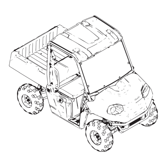
FEATURES AND CONTROLS FEATURES AND CONTROLS COMPONENT LOCATIONS ROPS Frame Cargo Box Hip Bars Fuel Cap Front Bumper/Brush Guard Muffler Headlights Cargo Box Release Lever Radiator Electric Compartment Tailgate... - Page 26 FEATURES AND CONTROLS CONSOLE Cup Holder 12V Auxiliary Outlet Instrument Cluster Steering Wheel Adjustment Lever MODE Button Ignition/Light Switch Gear Selector (Shifter) Storage Tray Turf Mode Switch Storage Compartment AUXILIARY OUTLET The vehicle is equipped with a 12-volt accessory outlet on the dash. Use the outlet to power an auxiliary light or other optional accessories or lights.
- Page 27 FEATURES AND CONTROLS SWITCHES IGNITION SWITCH/LIGHT SWITCH The ignition switch is a four-position, key-operated switch. The key can be removed from the switch when it is in the OFF position. The engine is off. Electrical circuits are off, except Acc, 12V. Lights On Lights are on.
- Page 28 Whenever the vehicle is left unattended, always place the transmission in PARK. Maintaining shift linkage adjustment is important to assure proper transmission function. Your Taylor-Dunn dealer can assist in resolving any shifting problems.
- Page 29 FEATURES AND CONTROLS NOTICE Do not attempt to shift the transmission while the vehicle is moving or damage to the transmission could result. Always shift when the vehicle is stationary and the engine is at idle. USING LOW GEAR Always shift into low gear for any of the following conditions. •...
- Page 30 FEATURES AND CONTROLS FOOT PEDALS BRAKE PEDAL Depress the brake pedal to slow or stop the vehicle. Apply the brakes while starting the engine. When the brake pedal is depressed, the brake light comes on. Check the brake light before each ride. 1.
- Page 31 FEATURES AND CONTROLS SEAT SEAT REMOVAL Pull up on the front of the seat and slide it toward the front of the vehicle. Install the seat by sliding the tabs into the rear of the seat base. Push down firmly on the front of the seat until the pins are fully seated into the grommets.
- Page 32 FEATURES AND CONTROLS 3. Release the strap, it will self tighten. 4. To release the seat belt, press the square red button in the buckle’s center. SEAT BELT INSPECTION Inspect all seat belts for proper operation before each use of the vehicle. 1.
- Page 33 If your factory-installed battery cannot maintain a charge because of operation in extreme cold or with multiple electrical accessories, you may need to purchase a 30 AH battery and a battery strap bracket. Your Taylor-Dunn dealer can assist. Your dealer can provide any installation procedures that may differ for an extreme use battery.
- Page 34 FEATURES AND CONTROLS INSTRUMENT CLUSTER Speedometer Indicator Lamps Mode Button Rider Information Center...
- Page 35 FEATURES AND CONTROLS INDICATOR LAMPS LAMP INDICATES CONDITION Vehicle Speed When standard mode is selected, speed displays in miles per hour. When metric mode is selected, speed displays in kilometers per hour. This lamp illuminates to indicate an overheated Over Temperature engine.
- Page 36 FEATURES AND CONTROLS RIDER INFORMATION CENTER The rider information center is located in the instrument cluster. All segments will light up for one second at start-up. If the instrument cluster fails to illuminate, a battery over-voltage may have occurred and the instrument cluster may have shut off to protect the electronic speedometer.
- Page 37 FEATURES AND CONTROLS MODE BUTTON The yellow button located near the instrument cluster is used to toggle through mode options available. DISPLAY UNITS The display can be changed to display either standard or metric units of measurement. To exit the set-up mode at any time, wait 10 seconds. The display automatically exits and returns to the odometer display.
- Page 38 FEATURES AND CONTROLS 4. Press and hold the MODE button until the next segment flashes. Release the button. 5. Repeat steps 3-4 twice to set the 10-minute and 1-minute segments. After completing the 1-minute segment, step 4 will save the new settings and exit the clock mode.
- Page 39 3. Record the three numbers displayed in the gear position, clock and odometer displays. 4. Press the MODE button to advance to the next error code. 5. Press and hold the MODE button to exit the diagnostics code menu. 6. Your authorized Taylor-Dunn dealer can provide code details and diagnosis.
-
Page 41: Operation
OPERATION OPERATION WARNING Failure to operate the vehicle properly can result in a collision, loss of control, accident or rollover, which may result in serious injury or death. Read and understand all safety warnings outlined in the safety section of this owner’s manual. - Page 42 OPERATION BRAKE SYSTEM BREAK-IN Apply only moderate braking force for the first 50 stops. Aggressive or overly forceful braking when the brake system is new could damage brake pads and rotors. CVT BREAK-IN (CLUTCHES/BELT) A proper break-in of the clutches and drive belt will ensure a longer life and better performance.
- Page 43 4. Engine exhaust fumes are poisonous. Never start the engine or let it run in an enclosed area. 5. Never operate with accessories not approved by Taylor-Dunn for use on this vehicle. 6. Operate this vehicle off-road only. Never operate this vehicle on any public street, road or highway, including dirt and gravel roads (unless designated for off-highway use).
- Page 44 Familiarize yourself with all laws and regulations concerning the operation of this vehicle in your area. Respect the environment in which you ride your vehicle. Find out where the designated riding areas are by contacting your Taylor-Dunn dealer, a local riding club, or local officials.
- Page 45 OPERATION COLD WEATHER OPERATION If the vehicle is used year-round, check the oil level frequently. A rising oil level could indicate the accumulation of contaminates such as water or excess fuel in the bottom of the crankcase. Water in the bottom of the crankcase can lead to engine damage and must be drained.
- Page 46 OPERATION DRIVING PROCEDURES DRIVING PROCEDURES 1. Read and understand the owner's manual and all warning and instruction labels before operating this vehicle. 2. Wear the recommended safety gear. 3. Perform the pre-ride inspection. 4. Sit in the driver's seat and fasten the seat belt. 5.
- Page 47 OPERATION DRIVING WITH A PASSENGER 1. Perform the pre-ride inspection. 2. Make sure all passengers are at least 12 years of age and tall enough to comfortably and safely sit in a passenger seat with the seat belt secured, put both feet on the floor and grasp the hand hold.
- Page 48 OPERATION DRIVING ON SLIPPERY SURFACES WARNING Skidding or sliding can cause loss of control or rollover (if tires regain traction unexpectedly). When operating on slippery surfaces such as ice or loose gravel, reduce speed and use extra caution to reduce the chance of skidding or sliding out of control.
- Page 49 OPERATION DRIVING UPHILL Whenever traveling uphill, follow these precautions: 1. Avoid excessively steep hills. 2. Always travel straight uphill. 3. Keep both feet on the floor. 4. Always check the terrain carefully before ascending any hill. Never climb hills with excessively slippery or loose surfaces. 5.
- Page 50 OPERATION DRIVING THROUGH WATER Your vehicle can operate through water up to a maximum recommended depth equal to the floorboards. NOTE If your vehicle becomes immersed or is operated in water that exceeds the floor level, service is required before starting the engine. Your dealer can provide this service.
- Page 51 OPERATION DRIVING IN REVERSE Follow these precautions when operating in reverse: 1. Always check for obstacles or people behind the vehicle. Always inspect left and right fields of vision before backing. 2. Always avoid backing downhill. 3. Back slowly. 4. Apply the brakes lightly for stopping. 5.
- Page 52 OPERATION HAULING CARGO WARNING Overloading the vehicle or carrying or towing cargo improperly can alter vehicle handling and may cause loss of control or brake instability. Always follow these precautions when hauling cargo: Never exceed the stated load capacity for this vehicle. REDUCE SPEED AND ALLOW GREATER DISTANCES FOR BRAKING WHEN HAULING CARGO.
- Page 53 OPERATION Loads should be centered and carried as low as possible in the box. For stability on rough or hilly terrain, reduce both speed and cargo. Exercise caution if the cargo load extends over the side of the box. Always read and understand the load distribution warnings listed on warning labels and in this manual.
- Page 54 OPERATION TOTAL TOWED TOTAL TOWED TOTAL HITCH MAXIMUM LOAD WEIGHT LOAD WEIGHT VERTICAL TOWING (LEVEL (15° GRADE) WEIGHT SPEED GROUND) 1500 lbs. 850 lbs. 150 lbs. 10 MPH (681 kg) (386 kg) (68.1 kg) (16 km/h) DUMPING THE CARGO BOX To dump the cargo box, do the following: 1.
-
Page 55: Emission Control Systems
EMISSION CONTROL SYSTEMS EMISSION CONTROL SYSTEMS NOISE EMISSION CONTROL SYSTEM Do not modify the engine, intake or exhaust components, as doing so may affect compliance with U.S.A. EPA noise control requirements (40 CFR 205) and local noise level requirements. OPERATION ON PUBLIC LANDS IN THE U.S.A. Your vehicle has a spark arrester that was tested and qualified to be in accordance with the USFS standard 5100-1C. -
Page 57: Maintenance
Any qualified repair shop or person may maintain, replace or repair the emission control devices or systems on your vehicle. An authorized Taylor-Dunn dealer can perform any service that may be necessary for your vehicle. Taylor-Dunn also recommends Taylor-Dunn parts for emissions-related service, however equivalent parts can be used. - Page 58 MAINTENANCE SEVERE USE DEFINITION • Frequent immersion in mud, water, or sand • Frequent or prolonged operation in dusty environments • Short trip cold wether operation • Racing or race-style high RPM use • Prolonged low speed, heavy load operation •...
- Page 59 MAINTENANCE MAINTENANCE INTERVAL (WHICHEVER COMES FIRST) MILES HOUR- CALEN- (KM) ITEM REMARKS Frame fasteners Pre-Ride Engine Oil Level Pre-Ride Inspect; clean often; replace as Air filter, pre-filter Daily needed Daily Coolant Check level Check operation; apply dielectric Head lamp / tail Daily grease to electrical connections if lamp / worklight...
- Page 60 MAINTENANCE MAINTENANCE INTERVAL (WHICHEVER COMES FIRST) MILES HOUR- CALEN- (KM) ITEM REMARKS Oil lines and Inspect for leaks and loose fittings 100 H fasteners Inspect level; change yearly Front Gearcase oil 100 H 1000 Change fluid Transmission fluid 100 H (1600) Cycle the key to prime and pressurize the fuel system.
- Page 61 Always perform the maintenance procedures as outlined in the Periodic Maintenance Chart. OIL RECOMMENDATIONS Taylor-Dunn recommends the use of POLARIS Synthetic 5W-50 or a equivalent oil. Refer to the specifications section of this manual for capacities. Follow the manufacturer's recommendations for ambient temperature operation.
- Page 62 MAINTENANCE OIL CHECK The oil dipstick and fill tube is located on the engine. Access the dipstick through the right rear wheel well. To check the oil, do the following: 1. Position the vehicle on a level surface. 2. Place the transmission in PARK. 3.
- Page 63 MAINTENANCE OIL AND FILTER CHANGE Always check and change the oil at the intervals outlined in the Periodic Maintenance Chart. The engine drain plug is located on the bottom of the crankcase. To change the oil and filter, do the following: 1.
- Page 64 MAINTENANCE 8. Using a cap-style oil filter wrench, turn the filter counter-clockwise to remove 9. Using a clean dry cloth, clean the filter sealing surface on the crankcase. Make sure the old filter o-ring is completely removed. 10. Lubricate the o-ring on the new filter with a film of fresh engine oil. Check to make sure the oring is in good condition.
- Page 65 SPARK PLUG GAP/TORQUE MODEL ELECTRODE GAP NEW OR USED PLUG TORQUE Taylor-Dunn® G-100 .031” (.7–.9 mm) 9 ft. lbs. (12 Nm) SPARK PLUG INSPECTION Spark plug condition is indicative of engine operation. The spark plug firing end condition should be read after the engine is warmed up and the vehicle is driven at higher speeds.
- Page 66 ADDING OR CHANGING COOLANT Taylor-Dunn recommends the use of POLARIS Antifreeze 50/50 Premix. This antifreeze is already premixed and ready to use. Do not dilute with water. To ensure that the coolant maintains its ability to protect the engine, we recommend that the system be completely drained every five (5) years and fresh Antifreeze 50/50 Premix added.
- Page 67 But if the overflow bottle has run dry, the level in the radiator should also be inspected. 5. Reinstall the pressure cap. Use of a non-standard pressure cap will not allow the recovery system to function properly. Your Taylor-Dunn dealer can provide the correct replacement part.
- Page 68 MAINTENANCE OVERFLOW BOTTLE COOLANT LEVEL Always check and change the coolant at the intervals outlined in the Periodic Maintenance Chart. Maintain the coolant level between the minimum and maximum marks on the bottle (when the fluid is cool). 1. Position the vehicle on a level surface. 2.
- Page 69 MAINTENANCE CONTINUOUSLY VARIABLE TRANSMISSION (CVT) SYSTEM WARNING Failure to comply with the instructions in this warning can result in severe injury or death. Do not modify any component of the CVT system. Doing so may reduce its strength so that a failure may occur at a high speed. The CVT system has been precision balanced.
- Page 70 12. Check for signs of damage to seals on the transmission and engine. If any seals appear to be damaged, your vehicle requires prompt service. Your Taylor-Dunn dealer can assist. Belt slip is responsible for creating excessive heat that destroys belts, wears clutch components and causes outer clutch covers to fail.
- Page 71 6. Allow the engine RPM to settle to idle speed. Apply the brakes. Shift the transmission to the lowest available range. 7. Test for belt slippage. If the belt slips, repeat the process. 8. Your vehicle requires service as soon as possible. Your Taylor-Dunn dealer can assist.
- Page 72 6. Take the vehicle in for service as soon as possible, whether you succeed in starting it or not. Your Taylor-Dunn dealer can provide the required service. 7. If water has been ingested into the CVT follow the procedure for drying.
- Page 73 NOTICE Use of a non-Taylor-Dunn approved air filter may cause engine damage. Always use a Taylor—Dunn approved replacement filter. 7. Make sure the filter is fully seated on the intake boot and that there is no gap between the filter and boot after installation.
- Page 74 MAINTENANCE SPARK ARRESTER WARNING Failure to heed the following warnings while servicing the spark arrester could result in serious injury or death. • Do not perform service on the spark arrester while the system is hot. Exhaust system temperatures can reach 1000° F. Allow components to cool sufficiently before proceeding.
- Page 75 MAINTENANCE WARNING After opening a bottle of brake fluid, always discard any unused portion. Never store or use a partial bottle. Brake fluid is hygroscopic, meaning it rapidly absorbs moisture from the air. The moisture causes the boiling temperature of the brake fluid to drop, which can lead to early brake fade and the possibility of accident or severe injury.
- Page 76 MAINTENANCE BRAKE INSPECTION WARNING Do not apply WD-40 or any petroleum product to brake discs. These types of products are flammable and may also reduce the friction between the brake pad and caliper. 1. Check the brake system for fluid leaks.
- Page 77 Improper tire inflation or the use of non-standard size or type of tires may adversely affect vehicle handling, which could result in vehicle damage or personal injury. Always maintain proper tire pressure. Always use Taylor-Dunn approved size and type of tires for this vehicle when replacing tires.
- Page 78 MAINTENANCE TIRE TREAD DEPTH Always replace tires when tread depth is worn to 1/8” (3 mm) or less. AXLE AND WHEEL NUT TORQUE SPECIFICATIONS Inspect the following items occasionally for tightness, and if they've been loosened for maintenance service. Do not lubricate the stud or the lug nut. 30 ft.
- Page 79 MAINTENANCE WHEEL INSTALLATION 1. Place the transmission in PARK. 2. Place the wheel on the hub with the valve stem toward the outside and rotation arrows on the tire pointing toward forward rotation. WARNING Improperly installed wheels can adversely affect tire wear and vehicle handling, which can result in serious injury or death.
- Page 80 MAINTENANCE ACCESSO- EPS (OPT) LIGHTS DRIVE...
- Page 81 MAINTENANCE LIGHTS Poor lighting can result in reduced visibility when driving. Headlight and taillight lenses become dirty during normal operation. Clean lights frequently and replace burned out lamps promptly. Do not operate this vehicle at night or in low light conditions until the headlight is replaced. Always make sure lights are adjusted properly for best visibility.
- Page 82 MAINTENANCE BATTERY WARNING Battery electrolyte is poisonous. It contains sulfuric acid. Serious burns can result from contact with skin, eyes or clothing. Antidote: External: Flush with water. Internal: Drink large quantities of water or milk. Follow with milk of magnesia, beaten egg, or vegetable oil.
- Page 83 MAINTENANCE BATTERY FLUID (CONVENTIONAL BATTERY) A poorly maintained battery will deteriorate rapidly. Check the battery fluid level often. Maintain the fluid level between the upper and lower level marks. Add only distilled water. Tap water contains minerals that are harmful to a battery.
- Page 84 MAINTENANCE BATTERY INSTALLATION Using a new battery that has not been fully charged can damage the battery and result in a shorter life. It can also hinder vehicle performance. Follow the battery charging instructions on page 83 before installing the battery. An optional extreme use battery may be available for your model.
- Page 85 MAINTENANCE BATTERY CHARGING (CONVENTIONAL BATTERY) 1. Remove the battery from the vehicle to prevent damage from leaking or spilled electrolyte during charging. 2. Charge the battery with a charging output no larger than 1/10 of the battery’s amp/hr rating. Charge as needed to raise the specific gravity to 1.270 or greater.
- Page 86 CLEANING AND STORAGE WASHING THE VEHICLE Keeping your Taylor-Dunn vehicle clean will not only improve its appearance but it can also extend the life of various components. NOTE High water pressure may damage components. Taylor-Dunn recommends washing the vehicle by hand or with a garden hose, using mild soap.
- Page 87 • Air intake components If an informational or graphic label becomes illegible or comes off, contact your Taylor-Dunn dealer to purchase a replacement. Replacement safety labels are provided by Taylor-Dunn at no charge. Grease all zerk fittings immediately after washing. Allow the engine to run for a while to evaporate any water that may have entered the engine or exhaust system.
- Page 88 MAINTENANCE CHROME WHEEL CARE (IF EQUIPPED) Proper maintenance will protect chrome wheels from corrosion, preserve wheel life and ensure a “like new” appearance for many years. Chrome wheels exposed to road salt (or salt in the air in coastal areas) are more susceptible to corrosion if not properly cleaned.
- Page 89 MAINTENANCE OIL AND FILTER Change the oil and filter. See page 59. AIR FILTER / AIR BOX Replace the air filter. See Maintenance Chapter. Clean the air box. FLUID LEVELS Inspect the fluid levels. Add or change fluids as recommended in the Periodic Maintenance Chart.
- Page 90 MAINTENANCE 3. Fill the fuel tank with fuel. 4. Check all the points listed in the Daily Pre-Ride Inspection. Tightness of the bolts, nuts and other fasteners should be checked by an authorized dealer or other qualified service facility. 5. Lubricate at the intervals outlined in the Periodic Maintenance Chart. WARNING Engine exhaust contains poisonous carbon monoxide and can cause loss of consciousness or death.
-
Page 91: Specifications
SPECIFICATIONS SPECIFICATIONS TAYLOR-DUNN® G–100 SPECIFICATIONS TAYLOR-DUNN G-100 Maximum Weight Capacity (includes 1000 lbs. (454 kg) weight of operator, passenger, cargo, accessories) Dry Weight 1080 lbs. (490 kg) Test GVW - Rollover Protection System 2750 lbs. (1247 kg) per OSHA 29 CFR (ROPS) 1928.53... - Page 92 SPECIFICATIONS TAYLOR-DUNN G-100 Fuel System Electronic Fuel Injection Ignition Timing ECU Controlled Spark Plug Autolite 5923 / 0.030” - 0.037” (0.85 +/- 0.08 mm) Lubrication System Wet Sump Cooling Liquid Front Suspension McPherson Strut w/9 in. (22.7 cm) of travel Rear Suspension Dual A-arm, Anti-Sway Bar w/10 in.
-
Page 93: Troubleshooting
See Intake Pre-Filters for more information. Inspect clutch system seals for damage if repeated leaking occurs. Your Taylor-Dunn dealer can assist. Clutch malfunction Check for fouled plug or foreign material in gas tank or fuel lines. Poor engine performance Your Taylor-Dunn dealer can assist. - Page 94 Inspect plug and replace if necessary No spark to spark plug Inspect plug and replace if necessary Water or fuel in crankcase Your Taylor-Dunn dealer can assist Low battery voltage Recharge the battery to 12.8 VDC Mechanical failure Your Taylor-Dunn dealer can assist...
- Page 95 TROUBLESHOOTING ENGINE PINGS OR KNOCKS POSSIBLE CAUSE SOLUTION Poor quality or low octane fuel Replace with recommended fuel Incorrect spark plug gap or Set gap to specs or replace plug heat range ENGINE RUNS IRREGULARLY, STALLS OR MISFIRES POSSIBLE CAUSE SOLUTION Fouled or defective spark plug Inspect, clean and/or replace spark plug...
- Page 96 TROUBLESHOOTING ENGINE STOPS OR LOSES POWER POSSIBLE CAUSE SOLUTION Out of fuel Refuel Kinked or plugged fuel vent Inspect and replace line Water is present in fuel Replace with new fuel Fouled or defective spark plug Inspect, clean and/or replace spark plug Worn or defective spark plug Your dealer can assist wires...
-
Page 97: Warranty
WARRANTY WARRANTY LIMITED WARRANTY Taylor-Dunn, 2114 W. Ball Rd., Anaheim, CA 92804 gives a TWO YEAR OR 2000 HOUR LIMITED WARRANTY on all components of your Taylor-Dunn vehicle against defects in material or workmanship. Taylor-Dunn further warrants that the spark arrester in this product will meet the efficiency requirements of... - Page 98 WARRANTY COVERAGE AND EXCLUSIONS LIMITATIONS OF WARRANTIES AND REMEDIES This Taylor-Dunn limited warranty excludes any failures that are not caused by a defect in material or workmanship. THIS WARRANTY DOES NOT COVER CLAIMS OF DEFECTIVE DESIGN. This warranty also does not cover acts of God, accidental damage, normal wear and tear, abuse or improper handling.
- Page 99 DEFECTIVE MATERIALS, COMPONENTS, OR PRODUCTS. THE REMEDIES SET FORTH IN THIS WARRANTY ARE THE ONLY REMEDIES AVAILABLE TO ANY PERSON FOR BREACH OF THIS WARRANTY. TAYLOR-DUNN SHALL HAVE NO LIABILITY TO ANY PERSON FOR INCIDENTAL, CONSEQUENTIAL OR SPECIAL DAMAGES OF ANY DESCRIPTION, WHETHER ARISING OUT OF EXPRESS OR IMPLIED WARRANTY OR ANY OTHER CONTRACT, NEGLIGENCE, OR OTHER TORT OR OTHERWISE.
- Page 100 WARRANTY HOW TO OBTAIN WARRANTY SERVICE If your vehicle requires warranty service, you must take it to a Taylor-Dunn Servicing Dealer. When requesting warranty service you must present your copy of the Warranty Registration Form to the dealer. (THE COST OF TRANSPORTATION TO AND FROM THE DEALER IS YOUR RESPONSIBILITY.) Taylor-Dunn suggests that you use your original selling...
- Page 101 This EPA emissions warranty period is extended for at least as long as the standard factory warranty that Taylor-Dunn provides on the vehicle as a whole. The EPA emissions warranty period does not further extend if you purchase additional warranty...
- Page 102 The exclusive remedy for breach of this limited warranty shall be, at the exclusive option of TAYLOR-DUNN, repair or replacement of any defective materials, components or products. THE...
- Page 103 WARRANTY Owners are responsible for performing the scheduled maintenance identified in the owner's manual. TAYLOR-DUNN may deny warranty claims for failures that have been caused by the owner's or operator's improper maintenance or use, by accidents for which TAYLOR—DUNN has no responsibility, or by acts of God.
-
Page 105: Maintenance Log
MAINTENANCE LOG MAINTENANCE LOG MAINTENANCE LOG Use the following chart to record periodic maintenance. DATE MILES (KM) TECHNICIAN SERVICE PERFORMED / OR HOURS COMMENTS... - Page 107 CVT Break-in (Clutches/Belt) ..40 Adding or Changing Coolant ..64 Age Restrictions ......15 Air Filter........71 Air Filter / Air Box....... 87 Descending Hills Improperly ..18 Auxiliary Outlet......24 Diagnostic Display Mode ..... 37 Axle and Wheel Nut Torque Display Units ......
- Page 108 Fluid Levels......87 Fog the Engine ......87 Maintenance Chart Key ....56 Fuel Cap........30 Maintenance Log..... 103 Fuel Safety....... 20 Fuel Stabilizer......86 Fuel Transport Warning....12 Fuse Box Diagram ..... 77 Fuses ........77 New Operator Driving Procedures ......
- Page 109 Towing Loads ......51 Trail Etiquette ......42 Radiator and Cooling Fan.... 65 Transmission ......62 Radiator Coolant Level ....65 Transporting the Vehicle....88 Registration......95 Trip Meter Mode ......36 Removal from Storage ....87 Turning Improperly..... 17 Removing Corrosion ....
- Page 111 To locate your nearest dealer, visit www.taylor-dunn.com Taylor-Dunn Manufacturing Company 2114 West Ball Rd. Anaheim, CA 92804 Part No. 9928677 Rev 01...
Need help?
Do you have a question about the G-100 2018 and is the answer not in the manual?
Questions and answers