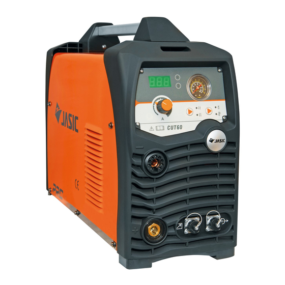
Summary of Contents for Jasic Plasma Cut 80
-
Page 1: Operator Manual
Plasma Cut Series Plasma Cut 60 (JP-61) Plasma Cut 80 (JP-81) Operator Manual... -
Page 2: Serial Number
Your new product Thank you for selecting this Jasic Technology, Wilkinson Star product. This product manual has been designed to ensure that you get the most from your new product. Please ensure that you are fully conversant with the information provided paying particular attention to the safety precautions. - Page 3 SAFETY These general safety norms cover both arc welding machines and plasma cutting machines unless otherwise noted. The equipment must only be used for the purpose it was designed for. Using it in any other way could result in damage or injury and in breach of the safety rules. Only suitably trained and competent persons should use the equipment.
- Page 4 If ventilation is poor, wear an approved respirator. Read and understand the Material Safety Data Sheets (MSDS’s) and the manufacturer’s instructions for metals, consumable, coatings, cleaners, and de-greasers. Do not weld in locations near any de-greasing, cleaning, or spraying operations. Be aware that heat and rays of the arc can react with vapours to form highly toxic and irritating gases.
- Page 5 Always ensure machine covers and protective devices are in operation. Precautions against fire and explosion Avoid causing fires due to sparks and hot waste or molten metal Ensure that appropriate fire safety devices are available near the cutting / welding area. Remove all flammable and combustible materials from the cutting / welding zone and surrounding areas Do not cut/weld fuel and lubricant containers, even if empty.
- Page 6 dangerous to the operator. When the equipment is scrapped, it should be dismantled separating components according to the type of materials. Do not dispose of the equipment with normal waste. The European Directive 2002/96/EC on Waste Electrical and Electronic Equipment states the electrical equipment that has reached its end of life must be collected separately and returned to an environmentally compatible recycling facility.
- Page 7 Unpacking Check the packaging for any signs of damage. Carefully remove the machine and retain the packaging until the installation is complete. Location The machine should be located in a suitable position and environment. Care should be taken to avoid moisture, dust, steam, oil or corrosive gases Place on a secure level surface and ensure that there is adequate clearance around the machine to ensure natural airflow.
- Page 8 Air pressure setting The machine should be connected to a suitable air supply, 4.5-5 Bar pressure. The embedded filter reducer is preset prior to leaving the factory, and users should not need to set it themselves. Please note this adjustment should be carried out by a competent person only. If for any reason the reducer needs to be adjusted then it needs to be done as follows: Switch off the machine.
- Page 9 workpiece.), and then push the torch trigger. After the arc is ignited and started, raise the cutting torch to the position about 1mm above the workpiece, and start cutting. Controls Digital Ammeter Power indicator Warning indicator Pressure guage Current adjustment knob 2T / 4T selector Air purge / cut selector Torch connector...
- Page 10 Panel Indicators Symbol Function Power indicator. It illuminates when the machine is powered on, and it flashes after arc is successfully ignited. Overheating indicator. It illuminates when the working temperature of the IGBT is overly high. When lit the machine stops working. 2T indicator: It illuminates when the machine is under 2T status.
-
Page 11: Maintenance And Troubleshooting
Maintenance and troubleshooting The following operation requires sufficient professional knowledge on electric aspects and comprehensive safety knowledge. Make sure the input cable of the machine is disconnected from the electricity supply and wait for 5 minutes before removing the machine covers. In order to guarantee that the arc welding machine works efficiently and in safety, it must be maintained regularly. -
Page 12: Technical Parameters
TECHNICAL PARAMETERS CUT 60 (JP-61) CUT 80 (JP-81) RATED INPUT POWER SUPPLY 3 PHASE 400V 50/60 Hz 3 PHASE 400V 50/60 Hz RATED INPUT CAPACITY (KVA) 10.8 14.4 POWER FACTOR RATED OUTPUT (A/V) 60/104 80/112 RATED DUTY CYCLE (%) NO LOAD VOLTAGE (V) ARC IGNITION MODE |NON HF NON HF... - Page 13 EXPOLDED PARTS LIST— JP-61 EXPOLDED PARTS LIST— JP-81 A WILKINSON STAR LIMITED PRODUCT 12-16 ISSUE 1...
-
Page 14: Parts List
Part No Part No EMC Board 10043995 Gas connector 10048726 2 Pin connector 10004691 Torch connector 10004644 Panel (middle) 10058211 Bracket 10058273 Jasic insert 10041712 4 pin connector 10035556 Base panel 10058232 Insulating cover 10037078 Support 10037028 Support 10049912 Deflector 10049881... - Page 15 Notes on cutting It is recommended not to ignite the arc in the air if not necessary. It will shorten the lifespan of the electrode and nozzle of the torch. It is recommended to initiate the cutting from the edge of workpiece, unless penetra- tion is needed.
- Page 16 JP 61-81 CUT 61 Order code JP– 61 CUT 81 Order code JP– 81 © Wilkinson Star Limited A WILKINSON STAR LIMITED PRODUCT 12-16 ISSUE 1...


Need help?
Do you have a question about the Plasma Cut 80 and is the answer not in the manual?
Questions and answers
Jasic Procut 60