Table of Contents
Advertisement
Quick Links
CDM-600L
Open Network Satellite Modem (2.4 kbps – 20 Mbps)
Installation and Operation Manual
(For Firmware Version 1.1.1 or higher)
IMPORTANT NOTE: The information contained in this document supersedes all previously published
information regarding this product. Product specifications are subject to change without prior notice.
Part Number MN/CDM600L.IOM
Revision 0
Advertisement
Table of Contents

Related Manuals for Comtech EF Data CDM-600L


Summary of Contents for Comtech EF Data CDM-600L
- Page 1 CDM-600L Open Network Satellite Modem (2.4 kbps – 20 Mbps) Installation and Operation Manual (For Firmware Version 1.1.1 or higher) IMPORTANT NOTE: The information contained in this document supersedes all previously published information regarding this product. Product specifications are subject to change without prior notice.
- Page 3 Change Specifics: USES The CDM-600L Satellite Modem is fitted with two fuses, one each for line and neutral connections. These are contained within the body of the IEC power connector, behind a small plastic flap.
- Page 5 Comtech EF Data is an ISO 9001 Revision 0 Registered Company. May 21, 2003 Copyright © Comtech EF Data, 2003. All rights reserved. Printed in the USA. Comtech EF Data, 2114 West 7th Street, Tempe, Arizona 85281 USA, 480.333.2200, FAX: 480.333.2161...
- Page 6 CDM-600L Satellite Modem Revision 0 Preface MN/CDM600L.IOM This page is intentionally blank...
-
Page 7: Table Of Contents
Table of Contents CHAPTER 1. INTRODUCTION .....................1–1 STANDARD FEATURES ....................1–2 1.1.1 AUPC ........................1–2 1.1.2 Software – Flash Upgrading ...................1–2 1.1.3 Verification ......................1–3 1.1.4 Data Interfaces......................1–3 MAJOR ASSEMBLIES....................1–3 FAST OPTIONS AND HARDWARE OPTIONS .............1–4 1.3.1 FAST Accessible Options ..................1–5 1.3.2 FAST System Theory....................1–5 1.3.3 Implementation .......................1–5 1.3.4... - Page 8 CDM-600L Satellite Modem Revision 0 Preface MN/CDM600L.IOM BALANCED G.703 INTERFACE CONNECTOR (P7)............5–7 BNC CONNECTORS .....................5–7 5.10 UNIT ALARMS (P5B) ....................5–8 5.11 AC POWER CONNECTOR ..................5–8 5.12 GROUND CONNECTOR ...................5–9 CHAPTER 6. FRONT PANEL OPERATION.................6–1 DESCRIPTION.......................6–1 OPENING SCREEN.......................6–5 MAIN MENU........................6–5 6.3.1 CONFIG ........................6–6...
- Page 9 CDM-600L Satellite Modem Revision 0 Preface MN/CDM600.IOM 9.3.2 D&I Framing......................9–3 IDR ..........................9–4 9.4.1 IDR Primary Data Interfaces ...................9–5 9.4.2 IDR Engineering Service Channel ................9–5 CHAPTER 10. CLOCK MODES AND DROP AND INSERT (D&I) ........10–1 10.1 TRANSMIT CLOCKING ...................10–1 10.1.1 Internal Clock ......................10–1 10.1.2...
- Page 10 End Of Packet.......................15–5 CHAPTER 16. BUC FSK COMMUNICATIONS ..............16–1 16.1 INTRODUCTION ......................16–1 16.2 MESSAGE STRUCTURE..................16–2 16.2.1 Command Message Structure (CDM-600L to BUC) ..........16–2 16.2.2 Response Message Structure (BUC to CDM-600L) ..........16–3 16.3 POWER CLASS .......................16–3 16.4 BUC OUTPUT POWER LEVELING .................16–3 CHAPTER 17.
- Page 11 Figure 7-7. 8-PSK/TCM Rate 2/3 with and without concatenated R-S Outer Code ......7–17 Figure 7-8. Comtech EF Data Turbo Product Codec Rate 3/4 QPSK/OQPSK, 8-PSK AND 16-QAM . 7–18 Figure 7-9. Comtech EF Data Turbo Product Codec Rate 7/8 QPSK/OQPSK, 8-PSK AND 16-QAM . 7–19 Figure 7-10.
- Page 12 CDM-600L Satellite Modem Revision 0 Preface MN/CDM600L.IOM Tables Table 5-1. External Connections......................5–2 Table 5-2. Overhead Interface Connector Pin Assignments ..............5–3 Table 5-3. Data Interface Connector Pin Assignments................5–4 Table 5-4. Audio Interface Connector Pin Assignments ................5–5 Table 5-5. Remote Control Interface Connector Pin Assignments ............5–5 Table 5-6.
- Page 13 E-Mail can be sent to the Customer Support Department at: service@comtechefdata.com Contact us via the web at www.comtechefdata.com. To return a Comtech EF Data product (in-warranty and out-of-warranty) for repair or replacement: • Request a Return Material Authorization (RMA) number from the Comtech EF Data Customer Support Department.
- Page 14 • To ensure that the product is not damaged during shipping, pack the product in its original shipping carton/packaging. • Ship the product back to Comtech EF Data. (Shipping charges should be prepaid.) For more information regarding the warranty policies, see Warranty Policy, p. xiv.
- Page 15 The user should observe the following instructions: IMPORTANT Fuses The CDM-600L is fitted with two fuses - one each for line and neutral connections. These are contained within the body of the IEC power inlet connector, behind a small plastic flap.
- Page 16 The equipment is not designed for connection to power system that has no direct connection to ground. The CDM-600L is shipped with a line inlet cable suitable for use in the country of operation. If it is necessary to replace this cable, ensure the replacement has an equivalent specification.
- Page 17 (Also tested to FCC Part 15 Class B) Immunity: EN 50082 Part 1 - Generic immunity standard, Part 1: Domestic, commercial and light industrial environment. Additionally, the CDM-600L has been shown to comply with the following standards: EN 61000-3-2 Harmonic Currents Emission EN 61000-3-3...
- Page 18 Disclaimer Comtech EF Data has reviewed this manual thoroughly in order that it will be an easy-to- use guide to your equipment. All statements, technical information, and recommendations in this manual and in any guides or related documents are believed...
-
Page 19: Chapter 1. Introduction
Chapter 1. INTRODUCTION The CDM-600L (Figure 1-1) is an Open Network Satellite Modem, intended for Intelsat applications. • It is compliant with IESS-308/-309/-310/-314/-315 specifications, but also adds significant other features in Closed Network modes. • It offers variable data rates from 2.4 to 20 Mbps, in BPSK, QPSK, Offset QPSK, 8-PSK, and 16-QAM modes. -
Page 20: Standard Features
Introduction MN/CDM600L.IOM Standard Features The CDM-600L provides a wealth of standard features which go far beyond the basic requirements of the Intelsat specifications. In Closed Network applications, to facilitate network management, the CDM-600L incorporates EDMAC, an acronym for Embedded Distant-end Monitor And Control. In this mode, an additional 5% overhead is combined with the traffic data, (1.5% in Turbo... -
Page 21: Verification
When normal operation is again selected, all of the previous values are restored. 1.1.4 Data Interfaces The CDM-600L includes, as standard, a universal data interface that eliminates the need to exchange interface cards for different applications. The interfaces offered include: • RS-422 (RS-530) DCE (at rates up to 10 Mbps) •... -
Page 22: Fast Options And Hardware Options
MN/CDM600L.IOM FAST Options and Hardware Options The CDM-600L is extremely flexible and powerful, and incorporates a large number of optional features. Some customers may not require all of these features, and therefore, in order to permit a lower initial cost, the modem may be purchased with only the desired features enabled. -
Page 23: Fast Accessible Options
These techniques allow the use of a unique access code to enable configuration of the available hardware. The access code can be purchased at any time from Comtech EF Data. Once obtained, the access code is loaded into the unit through the front panel keyboard or the rear remote port. -
Page 24: Supporting Hardware And Software
1.3.5 Supporting Hardware and Software The CDM-600L incorporates an FSK serial link that can be activated on the TX-IF port for purpose of communicating with an FSK capable BUC. In this manner, a user may monitor, configure, and control the BUC using the front panel display and keypad of the modem or the modem’s remote control interface. -
Page 25: Chapter 2. Installation
Chapter 2. INSTALLATION Unpacking Inspect shipping containers for damage. If shipping containers are damaged, keep them until the contents of the shipment have been carefully inspected and checked for normal operation. The modem and manual are packaged in pre-formed, reusable, cardboard cartons containing foam spacing for maximum shipping protection. -
Page 26: Mounting
MN/CDM600L.IOM Mounting If the CDM-600L is to be mounted in a rack, ensure that there is adequate clearance for ventilation, particularly at the sides. In rack systems where there is high heat dissipation, forced air cooling must be provided by top or bottom mounted fans or blowers. Under no circumstance should the highest internal rack temperature be allowed to exceed 50°C... -
Page 27: Figure 2-1. Installation Of The Optional Mounting Bracket, Kt/6228-2
CDM-600L Satellite Modem Revision 0 Installation MN/CDM600L.IOM Equipment Rack Mounting Rail #10 Socket head screw BRACKET BOLTS Support Bracket Bracket #10 Flat Washer #10 Hex Nut Back of Modem * Note: Components of mounting kit KT/6228-1 Figure 2-1. Installation of the Optional Mounting Bracket, KT/6228-2... -
Page 28: Configuration
–130 + 10log(symbol rate/4800) dBm to -130 + 10log(symbol rate/4800) +50 dBm. The CDM-600L includes an internal programmable 13, 18, or 24V LNB power supply at the receive IF connector, and optionally includes a 24 or 48V BUC power supply at the transmit IF connector. -
Page 29: Chapter 3. Functional Description
Chapter 3. FUNCTIONAL DESCRIPTION The CDM-600L has two fundamentally different types of interface - IF and data. • The data interface is a bi-directional path which connects with the customer’s equipment (assumed to be the DTE) and the modem (assumed to be the DCE). -
Page 30: Figure 3-1. Cdm-600L Modem Block Diagram
DTE equipment. Physically the CDM-600L modem is comprised of two main card assemblies. • The first of these is the baseband framer card, which includes all of the interface circuits, the framer/de-framer, plesiochronous/Doppler buffer, Reed Solomon outer codec, and the main microcontroller. -
Page 31: Chapter 4. Physical Description
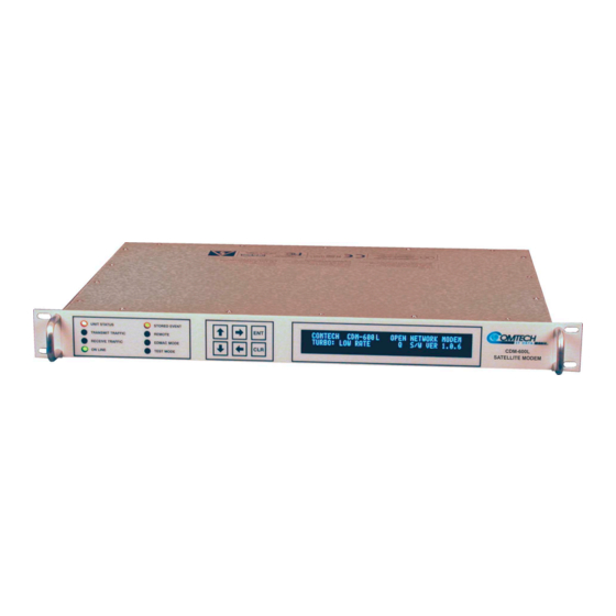
DESCRIPTION Introduction The CDM-600L is constructed as a 1U high rack-mounting chassis, which can be free- standing, if desired. Rack handles at the front facilitate removal from and placement into a rack. Figure 4-1 shows the front panel of the modem. -
Page 32: Rear Panel
There are eight LEDs on the front panel. The behavior of these LEDs is described in the ‘FRONT PANEL OPERATION’ section. Rear Panel Figure 4-2. CDM-600L Rear Panel External cables are attached to connectors on the rear panel of the CDM-600L. These comprise: • IEC line input connector •... - Page 33 CDM-600L Satellite Modem Revision 0 Physical Description MN/CDM600L.IOM IEC line input connector The IEC line input connector contains the ON/OFF switch for the unit. It is also fitted with two fuses - one each for line and neutral connections (or L1, L2, where appropriate).
- Page 34 CDM-600L Satellite Modem Revision 0 Physical Description MN/CDM600L.IOM External clock connector (J9) This is a BNC female connector. It is used for operating the buffer with an external station clock. It requires an RS-422 compatible level, so this unbalanced input should have a zero volt offset and a swing of at least ±...
- Page 35 CDM-600L Satellite Modem Revision 0 Physical Description MN/CDM600L.IOM IDI, DDO conectors (J10A and J11A) DROP AND INSERT ONLY. Two additional female BNC 75Ω connectors for unbalanced operation at the G.703 data rate of E1 (2.048 Mbps). These are the Insert Data In and Drop Data Out port.
-
Page 36: Dimensional Envelope
CDM-600L Satellite Modem Revision 0 Physical Description MN/CDM600L.IOM Dimensional Envelope 18.0 1.72 16.53 19.0 Figure 4-3. CDM-600L Dimensional Envelope 4–6... -
Page 37: Chapter 5. Connector Pinouts
Chapter 5. CONNECTOR PINOUTS Connector Overview The rear panel connectors (Figure 5-1) provide all necessary external connections between the modem and other equipment. 5–1... - Page 38 CDM-600L Satellite Modem Revision 0 Connector Pinouts MN/CDM600L.IOM Figure 5-1. CDM-600L Rear Panel Table 5-1. CDM-600L External Connections Name Connector Type Function RX IF RF Input TX IF RF Output Aux Serial USB Type B (female) Auxiliary Serial Overhead 25-pin D (male)
-
Page 39: Overhead Interface Connector (P3A)
CDM-600L Satellite Modem Revision 0 Connector Pinouts MN/CDM600L.IOM Overhead Interface Connector (P3A) The overhead interface connector is a 25-pin male D interface located on the rear panel of the modem. Refer to Table 5-2 for pin assignments. Table 5-2. Overhead Interface Connector Pin Assignments... -
Page 40: Data Interface Connector (P3B)
CDM-600L Satellite Modem Revision 0 Connector Pinouts MN/CDM600L.IOM Data Interface Connector (P3B) The Data Interface connector, a 25-pin D type female, conducts data input and output signals to and from the modem, and connects to customer’s terrestrial equipment, breakout panel, or protection switch. Refer to Table 5-3 for pin assignments. -
Page 41: Audio Interface Connector (P4A)
CDM-600L Satellite Modem Revision 0 Connector Pinouts MN/CDM600L.IOM Audio Interface Connector (P4A) The Audio interface connection is a 9-pin female D connector located on the rear panel of the modem. Refer to Table 5-4 for pin assignments. Table 5-4. Audio Interface Connector Pin Assignments... -
Page 42: Idr Backward Alarms Connector (P5A)
CDM-600L Satellite Modem Revision 0 Connector Pinouts MN/CDM600L.IOM IDR Backward Alarms Connector (P5A) The IDR Alarm interface connection is a 15-pin female connector located on the rear panel of the modem. Refer to Table 5-6 for pin assignmernts. Table 5-6. IDR Alarm Interface Connector Pin Assignments... -
Page 43: Balanced G.703 Interface Connector (P7)
CDM-600L Satellite Modem Revision 0 Connector Pinouts MN/CDM600L.IOM Balanced G.703 Interface Connector (P7) The Balanced G.703 connection is a 15-pin female connector located on the rear panel of the modem. Refer to Table 5-8 for pin assignments. Table 5-8. Balanced G.703 Interface Connector Pin Assignments... -
Page 44: Unit Alarms (P5B)
CDM-600L Satellite Modem Revision 0 Connector Pinouts MN/CDM600L.IOM 5.10 Unit Alarms (P5B) Unit alarms are provided on a 15-pin male connector located on the rear panel of the modem. Refer to Table 5-10 for pin assignments. Table 5-10. Alarm Interface Connector Pin Assignments... -
Page 45: Ground Connector
CDM-600L Satellite Modem Revision 0 Connector Pinouts MN/CDM600L.IOM 5.12 Ground Connector A #10-32 stud on the rear panel of the modem is used for connecting a common chassis ground among equipment. Note: The AC power connector provides the safety ground. - Page 46 CDM-600L Satellite Modem Revision 0 Connector Pinouts MN/CDM600L.IOM This page is intentionally left blank. 5–10...
-
Page 47: Chapter 6. Front Panel Operation
Description Figure 6-1. Front Panel View The user can fully control and monitor the operation of the CDM-600L from the front panel, using the keypad and display. Nested menus are used, which display all available options, and prompt the user to carry out a required action. -
Page 48: Table 6-1. Front Panel Led Indicators
CDM-600L Satellite Modem Revision 0 Front Panel Operation MN/CDM600L.IOM If the user were to display the same screen for weeks at a time, the display could become ‘burnt’ with this image. To prevent this, the unit has a ‘screen saver’ feature which will activate after 1 hour. -
Page 49: Figure 6-2. Keypad
CDM-600L Satellite Modem Revision 0 Front Panel Operation MN/CDM600L.IOM The keypad is shown in Figure 6-2: Figure 6-2. Keypad The function of these keys is as follows: ENTER This key is used to select a displayed function or to execute a modem configuration change. - Page 50 BUC-FSK BUC-CONFIG BUC-FSK FSK LINK, TX OUTPUT, LEVELING, ADDRESS BUC-LO BUC-CONFIG PWR, 10mhZ, ALARM CIRCUITS, PWR-UP DELAY LNB-CONFIG BUC-LO LO FREQ. MIX LNB-LO LNB-CONFIG VOLTAGE, PWR, 10MHz, ALARM LIMIT LNB-LO LO FREQ. MIX FAST Figure 6-3. CDM-600L Menu Trees 6–4...
-
Page 51: Opening Screen
CDM-600L Satellite Modem Revision 0 Front Panel Operation MN/CDM600L.IOM Opening Screen This screen is displayed whenever power is first applied to the unit: COMTECH CDM-600L OPEN NETWORK MODEM TURBO: LOW RATE S/W VER 1.1.39 The bottom line displays which Turbo codec (if any) is installed, and the internal software version. -
Page 52: Config
CDM-600L Satellite Modem Revision 0 Front Panel Operation MN/CDM600L.IOM 6.3.1 CONFIG CONFIG: MODE CLOCKS D&I REFERENCE EDMAC MISC REMOTE MASK STATS The sub-branches available are: Permits the user to completely configure the unit, being prompted, step by step, to make choices, or edit data. This is highly recommended for new users, as it will clearly lead the user through all the configuration parameters. - Page 53 CDM-600L Satellite Modem Revision 0 Front Panel Operation MN/CDM600L.IOM 6.3.1.1 CONFIG: ALL ALL = START (STOP, START) Use the [↑] and [↓] arrow keys to select START or STOP, then press ENTER. The user may then configure the unit, in a step-by-step process by viewing each menu in succession.
- Page 54 CDM-600L Satellite Modem Revision 0 Front Panel Operation MN/CDM600L.IOM The AUDIO choice permits the user to carry 2 x 32 kbps ADPCM audio as the primary data. This interface type forces IBS or EDMAC as the available framing types. The second option is the Framing type.
- Page 55 CDM-600L Satellite Modem Revision 0 Front Panel Operation MN/CDM600L.IOM To avoid the TX Carrier from being turned off when the demodulator loses lock for a very short period of time, the demodulator must be unlocked continuously for a period of 10 seconds before the transmit carrier is inhibited.
- Page 56 CDM-600L Satellite Modem Revision 0 Front Panel Operation MN/CDM600L.IOM If TARGET-EbNo/RANGE is selected, the following menu will be displayed: MINIMUM EbNo OF REMOTE MODEM = 5.0dB MAXIMUM PERMITTED POWER INCREASE = 9dB Edit Procedures: • Edit the target Eb/No of the remote modem. The default value is 3.0 dB, and upper limit is 9.9 dB.
- Page 57 • IDR (194/178), open network • UNFRAMED (220/200), closed network • LEGACY COMTECH EF DATA (225,205, with V.35 scrambling), closed network CONFIG: TX: MODULATION MODULATION = QPSK (B,Q,OQ,8-PSK, 16QAM) FEC RATE = 1/2 (1/2,3/4,7/8) Select one of the parameters using the [←] [→] arrow keys, and then edit using the [↑] [↓] arrow keys.
- Page 58 CDM-600L Satellite Modem Revision 0 Front Panel Operation MN/CDM600L.IOM The Modulation Type and FEC rate choices are dictated by the Encoder type: No Encoder: BPSK Fixed at 1/1 QPSK, OQPSK Fixed at 1/1 Non-Turbo Encoder: BPSK Fixed at Rate 1/2...
- Page 59 CDM-600L Satellite Modem Revision 0 Front Panel Operation MN/CDM600L.IOM CONFIG: TX: SCRAMBLER TX SCRAMBLER = NORMAL (NORMAL,OFF) ENCODER SCRAMBLER Select either ON or OFF, using the [↑] [↓] arrow keys, then press ENTER. The choice of scrambler is selected automatically, and will be depend on the exact operating mode.
- Page 60 IESS-310 (219/201), open or closed network • IBS (126/112), open or closed network • EDMAC (200/180), closed network • IDR (225/205), open network • IDR (194/178), open network • UNFRAMED (220/200), closed network • LEGACY COMTECH EF DATA (225,205, with V.35 scrambling), closed network 6–14...
- Page 61 CDM-600L Satellite Modem Revision 0 Front Panel Operation MN/CDM600L.IOM CONFIG: RX: DEMODULATION DEMODULATION = QPSK(B,Q,OQ,8-PSK,16QAM) FEC RATE = 1/2 (1/2,3/4,7/8) Select one of the parameters using the [←] [→] arrow keys, and then edit using the [↑] [↓] arrow keys. Edit the Modulation type and the FEC rate.
- Page 62 CDM-600L Satellite Modem Revision 0 Front Panel Operation MN/CDM600L.IOM with certain older equipment). Select either ON or OFF, using the [↑] [↓] arrow keys, then press ENTER. CONFIG: RX: DESCRAMBLER RX DESCRAMBLER = NORMAL (NORMAL,OFF) DECODER DESCRAMBLER Select either ON or OFF, using the [↑] [↓] arrow keys, then press ENTER.
- Page 63 CDM-600L Satellite Modem Revision 0 Front Panel Operation MN/CDM600L.IOM CONFIG: CLOCKS: TX CLOCK TRANSMIT CLOCK = INTERNAL(SCT) (INT(SCT),TX-TERR(TT),RX-LOOP,EXT-REF) Select from the choices shown in the parentheses using the [↑] [↓] arrow keys, then press ENTER. • INTERNAL (SCT) indicates that the unit will supply a clock to the DTE, which is derived from its internal high-stability source.
- Page 64 CDM-600L Satellite Modem Revision 0 Front Panel Operation MN/CDM600L.IOM CONFIG:CLOCKS: RX BUFFER/CLOCK CLK= RX-SAT (RX-SAT,TX-TERR,EXT-REF,INS) BUFFER-SIZE = 00016bytes(00002ms) CENTER sing the [←] [→] arrow keys keys, select one of the three parameters on the screen to edit. Edit the RX clock options using the [↑] [↓] arrow keys, then press ENTER...
- Page 65 CDM-600L Satellite Modem Revision 0 Front Panel Operation MN/CDM600L.IOM CONFIG: CLOCKS: EXTERNAL-CLOCK EXTERNAL CLOCK= 02048.000 kHz EXT CLK TYPE= UNBAL (UNBAL,BAL) To edit the EXT-REF CLOCK, select the digit to be edited using the [←] [→] arrow keys. Edit the value of the digit using the [↑] [↓] arrow keys. Press ENTER.
- Page 66 CDM-600L Satellite Modem Revision 0 Front Panel Operation MN/CDM600L.IOM CONFIG: DROP & INSERT: DROP CHANNEL TIMESLOTS DRP-CH: 1 TS: 01 Select the Time-slot to edit using the [←] [→]arrow keys and edit the value using the [↓] [↑] arrow keys, then press ENTER. The number of Channels and Time-slots shown depends on the data rate.
- Page 67 CDM-600L Satellite Modem Revision 0 Front Panel Operation MN/CDM600L.IOM 6.3.1.8 CONFIG: EDMAC EDMAC MODE = MASTER (IDLE/MASTER/SLAVE) EDMAC ADDRESS = XXXX Select either IDLE, MASTER, or SLAVE, using the [↑] [↓] arrow keys, then press ENTER. An EDMAC MASTER is a unit which is local to the M&C computer, and which passes messages, via the overhead, to a distant-end modem.
- Page 68 CDM-600L Satellite Modem Revision 0 Front Panel Operation MN/CDM600L.IOM CONFIG: MISC: IDR-ESC-TYPE TX–IDR-TYPE: 64k DATA (64k DATA,AUDIO) RX-IDR-TYPE: 64k DATA (64k DATA,AUDIO) Parameters may only be edited if the Interface Type is G.703. Parameters may only be edited if the Framing Mode is IDR.
- Page 69 CDM-600L Satellite Modem Revision 0 Front Panel Operation MN/CDM600L.IOM 6.3.1.10 CONFIG: REMOTE CONTROL REMOTE CONTROL = LOCAL (LOCAL,REMOTE) Select LOCAL or REMOTE using the [↑] [↓] arrow keys, then press ENTER. If LOCAL is selected, the REMOTE CONTROL is disabled. Remote monitoring is still possible.
- Page 70 CDM-600L Satellite Modem Revision 0 Front Panel Operation MN/CDM600L.IOM 6.3.1.11 CONFIG: MASK These sub-menus permit the user to selectively mask, or make active, various alarms and traffic conditions that are monitored in the unit. CONFIGURE ALARM MASK: BUFFER RXIF SAT-ALM TERR-ALM Use the [←] [→] arrow keys to select the parameter to edit, then press ENTER.
- Page 71 CDM-600L Satellite Modem Revision 0 Front Panel Operation MN/CDM600L.IOM CONFIG: MASK: RX-IF RXIF: AGC = ACTIVE (ACTIVE,MASK) EbNo = MASKED (ACTIVE,MASK) Use the [←] [→] arrow keys to select the parameter to edit: AGC or Eb/No. Select either ACTIVE or MASKED, using the [↑] [↓] arrow keys, then press ENTER.
- Page 72 CDM-600L Satellite Modem Revision 0 Front Panel Operation MN/CDM600L.IOM CONFIG: MASK: TERR-ALM TERR-ALM: TX = ACTIVE (ACTIVE,MASK) RX = OFF (OFF,ENABLED) These alarms are only valid for D&I operation. Use the [←] [→] arrow keys to select the parameter to edit. Edit the alarms using the [↑] [↓] arrow keys, then press ENTER.
-
Page 73: Test
CDM-600L Satellite Modem Revision 0 Front Panel Operation MN/CDM600L.IOM 6.3.2 TEST MODEM TEST MODE = NORMAL ↓ ↓ ↓ ↓ (NORM,TX-CW,TX-1/0,IF ,DIG ,I/O Select Test Mode or Normal Operation from the parameters shown in the parentheses using the [↑] [↓] arrow keys, then press ENTER. -
Page 74: Figure 6-4. Loopback Modes
CDM-600L Satellite Modem Revision 0 Front Panel Operation MN/CDM600L.IOM Figure 6-4. Loopback Modes 6–28... -
Page 75: Information
CDM-600L Satellite Modem Revision 0 Front Panel Operation MN/CDM600L.IOM 6.3.3 INFORMATION INFO: ALL ID FORMAT TX RX CLOCKS EDMAC DROP INSERT REMOTE ALARM-MASK MISC Select information to view using the [←][→] arrow keys, then press ENTER. Note: INFO screens display information on the current configuration of the modem without risking inadvertent changes. - Page 76 CDM-600L Satellite Modem Revision 0 Front Panel Operation MN/CDM600L.IOM 6.3.3.4 INFO: TX TX:ON 1200.0000MHz PWR=-10.0 TSI=N VIT+RS:220/220 00604.000 QPSK 1/2 SCRM A sample display of TX Info is shown. The information displayed here is as follows: Top Line: TX carrier...
- Page 77 CDM-600L Satellite Modem Revision 0 Front Panel Operation MN/CDM600L.IOM 6.3.3.6 INFO: CLOCKS CLOCKS: TX=INT(SCT) RX=RX-SAT REF=INT BUFFER-SIZE=00016 The TX Clock, RX Clock, REF Clock, and Buffer information is displayed. 6.3.3.7 INFO: EDMAC EDMAC FUNCTION= ON EDMAC MODE= MASTER EDMAC ADDR= 0020 This screen shows if EDMAC is enabled or not.
- Page 78 CDM-600L Satellite Modem Revision 0 Front Panel Operation MN/CDM600L.IOM 6.3.3.10 INFO: REMOTE REMOTE-CONTROL= LOCAL ADDRESS= 0000 INTERFACE = RS-232 9600 BAUD N81 This screen shows if the unit is in Local or Remote mode, provides the details of the electrical interface type selected, the unit’s address and the baud rate selected. Pressing ENTER takes the user back to the previous menu.
-
Page 79: Monitor
CDM-600L Satellite Modem Revision 0 Front Panel Operation MN/CDM600L.IOM 6.3.4 MONITOR MONITOR: LIVE-ALARMS STORED-EVENTS STATISTICS RX-PARAMS AUPC-PARAM Select the parameter to Monitor using the [←][→] arrow keys, then press ENTER. 6.3.4.1 MONITOR: LIVE-ALARMS LIVE UNIT= NONE NET= NONE ALARMS RECV=DEMOD LOCK XMT= NONE An example of an Alarm screen is shown. - Page 80 CDM-600L Satellite Modem Revision 0 Front Panel Operation MN/CDM600L.IOM 6.3.4.3 MONITOR: STATISTICS STATISTICS: STA114: 16.0,16.0,9.0,9.0 09/12/99 14:48:06 CLEAR ALL: NO (N/Y) The user may scroll backwards or forwards through the entries in the statistics log, using the [↑] [↓] arrow keys. Pressing ENTER or CLEAR will take the user back to the previous menu.
- Page 81 CDM-600L Satellite Modem Revision 0 Front Panel Operation MN/CDM600L.IOM 6.3.4.4 MONITOR: RX PARAMETERS ∆F=+11.7kHz RX=PARAMETERS: EbNo=11.4dB BER=0.0E-9 BUFFER=51% RX-LEVEL=-43dBm If the demodulator is locked, this screen shows the following: Eb/No This shows the value of Eb/No calculated by the demodulator. The value referred to here is the energy per information bit (Ebi), divided by the noise spectral density (No).
-
Page 82: Store/Load
CDM-600L Satellite Modem Revision 0 Front Panel Operation MN/CDM600L.IOM 6.3.4.7 BUC:CURRENT = 0000mA VOLT = 47.9V CLASS = N/A PWR = N/A Amb = N/A PLL = N/A VER = NA CURRENT If a BUC supply is installed, displays measured BUC load current. - Page 83 CDM-600L Satellite Modem Revision 0 Front Panel Operation MN/CDM600L.IOM 6.3.5.2 STORE/LOAD: EDIT CONFIGURATION EDIT CONFIGURATION NUMBER 0x Each configuration may have a name or description entered or edited using the [↑] [↓] arrow keys, then press ENTER. 6.3.6 UTILITIES UTILITIES:...
- Page 84 CDM-600L Satellite Modem Revision 0 Front Panel Operation MN/CDM600L.IOM 6.3.6.3 UTILITIES: LAMP FRONT PANEL LAMP TEST: DISABLED (ENABLED, DISABLED) Select enable or disable, using the [↑][↓] arrow keys, then press ENTER. This will test all of the LEDs on the front panel then resume normal operations.
- Page 85 MN/CDM600L.IOM 6.3.7 The ODU menu allows the user to access an FSK menu that permits the CDM-600L to interface directly with an FSK-capable BUC. The interface is accomplished using a low- speed, half-duplex FSK link on the TX IF port, with a carrier frequency around 650 kHz.
- Page 86 CDM-600L Satellite Modem Revision 0 Front Panel Operation MN/CDM600L.IOM 6.3.7.1 ODU: BUC-FSK FSK: LINK =OFF TX–OUTPUT=N/A LEVELING=N/A ADDRESS=N/A Select a parameter to edit using the [←] [→] arrow keys. LINK Turns the FSK communications with the BUC ON and OFF. Use [↑] [↓] arrow keys to select ON and OFF and press ENTER.
- Page 87 CDM-600L Satellite Modem Revision 0 Front Panel Operation MN/CDM600L.IOM ODU: BUC-LO BUC-LO: FREQUENCY = 00000 MHz MIX = HIGH (-) Select a parameter to edit using the [←] [→] arrow keys. FREQUENCY Sets the LO frequency in the BUC for the up conversion. Entering a...
-
Page 88: Fast
FAST is the way to enable new options in the modem. Obtain the FAST code for the new option from Comtech EF Data. Enter the code carefully. Use the [←][→] arrow keys to move the cursor to each character. Use the [↑] [↓] arrow keys to edit the character, then press ENTER. - Page 89 CDM-600L Satellite Modem Revision 0 Front Panel Operation MN/CDM600L.IOM 6.3.8.2 FAST: VIEW VIEW OPTIONS: 10 9 8 7 6 5 4 3 2 1 Special Option 1 Installed Use the [←][→] arrow keys to show which FAST options are currently installed.
- Page 90 CDM-600L Satellite Modem Revision 0 Front Panel Operation MN/CDM600L.IOM This page is intentionally left blank. 6–44...
-
Page 91: Chapter 7. Forward Error Correction Options
Turbo Coding represents a very significant development in the area of FEC, and optionally, the CDM-600L may be fitted with one of two Turbo Product Codecs They are plug-in daughter cards (SIMM modules), both field upgradeable. The Low Rate option provides data rate capability up to 5 Mbps, and code rates limited to Rate 5/16 (BPSK, Rate 21/44 (BPSK) and Rate 3/4 (QPSK, Offset QPSK, 8-PSK and 16-QAM). -
Page 92: Sequential
Eb/No). This is not true of the Sequential decoding method, as explained in the section below. Note that in BPSK mode, the CDM-600L only permits a coding rate of 1/2. Because the method of convolutional coding used with Viterbi, the encoder does not preserve the original data intact, and is called non-systematic. -
Page 93: Reed-Solomon Outer Codec
Viterbi or Sequential decoder is spread out over a number of interleaving frames, so errors entering the R-S decoder do not exceed its capacity to correct those errors. In the case of the CDM-600L, different R-S code rates are used, according to the mode of operation:... -
Page 94: Table 7-3. Concatenated Rs Coding Summary
This may be due to the carrier-recovery circuits, or the synchronization threshold of the primary FEC device, or both. In the CDM-600L, and Rate 1/2 operation, this threshold is around 4 dB Eb/No. Below this value, operation is not possible, but above this value, the error performance of the concatenated R-S system produces exceptionally low error rates for a very small increase in Eb/No. -
Page 95: Trellis Coding (Fast Option)
– the natural consequences of the higher-order modulation. The CDM-600L fully implements the IESS-310 specification at data rates up to 18 Mbps. In accordance with the specification, the R-S outer code can be disabled. Performance curves for both cases are shown in the following Figures. -
Page 96: Turbo Product Codec (Hardware Option)
When the CDM-600L was first released in July 2001, it was limited to these original code rates, at data rates up to 5 Mbps. In November 2001, 16-QAM was added (Viterbi/Reed- Solomon), while at the same time, Rate 3/4 TPC was added for both 8-PSK and 16- QAM. -
Page 97: End-To-End Processing Delay
5% FEC overhead, but yields almost identical coding gain to Rate 1/2 Viterbi at a BER of 1 x 10 . Below is a listing of all the available TPC modes and rates in the CDM-600L, as at April 2002: Table 7-5. -
Page 98: Comparison Of All Tpc Modes
(9.5 dB) The occupied bandwidth is defined at the width of the transmitted spectrum taken at the –10 dB points on the plot of power spectral density. This equates to 1.19 x symbol rate for the CDM-600L transmit filtering. Included for comparative purposes... -
Page 99: Uncoded Operation (No Fec)
There are occasions where a user may wish to operate a satellite link with no forward error correction of any kind. For this reason, the CDM-600L offers this uncoded mode for three modulation types - BPSK, QPSK and Offset QPSK. However, the user should be aware of some of the implications of using this approach. - Page 100 The problem becomes progressively better with increasing symbol rate. Comtech EF Data cannot be held responsible for incorrect operation if the user does not adhere to these guidelines when using uncoded operation.
- Page 101 CDM-600L Satellite Modem Revision 0 Forward Error Correction Options MN/CDM600L.IOM Eb/No in dB 1E-1 Uncoded BPSK/QPSK Viterbi Decoding 1E-2 Typical Performance 1E-3 1E-4 1E-5 1E-6 Specification limit, Rate 7/8 1E-7 Coding 1E-8 Specification Specification limit, Rate 3/4 limit Rate 1/2...
-
Page 102: Figure 7-2. Sequential Decoding 64 Kbps
CDM-600L Satellite Modem Revision 0 Forward Error Correction Options MN/CDM600L.IOM Eb/No in dB 1E-1 Sequential Uncoded BPSK/QPSK Decoding 64 kbps 1E-2 Typical 1E-3 Performance 1E-4 1E-5 1E-6 Specification 1E-7 limit, Rate 7/8 Coding 1E-8 Specification Specification limit Rate 1/2 limit, Rate 3/4... - Page 103 CDM-600L Satellite Modem Revision 0 Forward Error Correction Options MN/CDM600L.IOM Eb/No in dB 1E-1 Sequential Uncoded BPSK/QPSK Decoding 1024 kbps 1E-2 1E-3 Typical Performance 1E-4 1E-5 1E-6 Specification 1E-7 limit, Rate 7/8 Coding 1E-8 Specification limit Rate 1/2 Specification Coding...
- Page 104 CDM-600L Satellite Modem Revision 0 Forward Error Correction Options MN/CDM600L.IOM Eb/No in dB 1E-1 Sequential Uncoded BPSK/QPSK Decoding 2048 kbps 1E-2 1E-3 1E-4 1E-5 1E-6 Typical performance, Rate 7/8 Coding 1E-7 1E-8 Typical Typical performance, performance, Rate 3/4 Rate 1/2...
-
Page 105: Figure 7-5. Viterbi With Concatenated R-S Outer Code
CDM-600L Satellite Modem Revision 0 Forward Error Correction Options MN/CDM600L.IOM Eb/No in dB 1E-1 Viterbi with Uncoded BPSK/QPSK concatenated RS 220,200 1E-2 Outer Code Sync threshold, Rate 3/4 1E-3 Sync threshold, Rate 7/8 1E-4 Combined sync 1E-5 threshold, demod and Viterbi... -
Page 106: Figure 7-6. Sequential With Concatenated R-S Outer Code
CDM-600L Satellite Modem Revision 0 Forward Error Correction Options MN/CDM600L.IOM Eb/No in dB 1E-1 Sequential Uncoded BPSK/QPSK with concatenated 1E-2 RS 220,200 Outer Code 512 kbps 1E-3 1E-4 Combined sync threshold, demod and Sequential 1E-5 Decoder, Rate 1/2 Sync threshold,... -
Page 107: Figure 7-7. 8-Psk/Tcm Rate 2/3 With And Without Concatenated R-S Outer Code
CDM-600L Satellite Modem Revision 0 Forward Error Correction Options MN/CDM600L.IOM Eb/No in dB 1E-1 8-PSK/TCM Rate 2/3 Uncoded BPSK/QPSK Decoding, with and without 219, 201 RS 1E-2 Outer Code Perf ormance with CDM-600 Firmware Version 1.1.5 (or higher) 1E-3 1E-4... -
Page 108: Figure 7-8. Comtech Ef Data Turbo Product Codec Rate 3/4 Qpsk/Oqpsk, 8-Psk And 16-Qam
Spec limit Rate 3/4 Uncoded 8-PSK 8-PSK 1E-4 Spec limit Rate 3/4 QPSK/OQPSK 1E-5 1E-6 1E-7 Spec limit Rate 3/4 16-QAM 1E-8 Typical performance 1E-9 Figure 7-8. Comtech EF Data Turbo Product Codec Rate 3/4 QPSK/OQPSK, 8-PSK AND 16-QAM 7–18... -
Page 109: Figure 7-9. Comtech Ef Data Turbo Product Codec Rate 7/8 Qpsk/Oqpsk, 8-Psk And 16-Qam
Spec limit Rate 7/8 Spec limit 8-PSK Rate 7/8 Uncoded QPSK/OQPSK 8-PSK 1E-4 1E-5 1E-6 1E-7 Spec limit Rate 7/8 16-QAM 1E-8 Typical performance 1E-9 Figure 7-9. Comtech EF Data Turbo Product Codec Rate 7/8 QPSK/OQPSK, 8-PSK AND 16-QAM 7–19... -
Page 110: Figure 7-10. Rate 1/2 Qpsk, Rate 0.95 Qpsk And Rate 0.95 8-Psk
CDM-600L Satellite Modem Revision 0 Forward Error Correction Options MN/CDM600L.IOM Eb/No in dB 1E-1 Comtech Turbo Product Codec Rate 1/2 QPSK/OQPSK Uncoded Rate 0.95 QPSK/OQPSK BPSK/QPSK 1E-2 and 8-PSK Performance with CDM-600 Firmware Version 1.1.5 (or higher) Uncoded 8-PSK 1E-3... -
Page 111: Figure 7-11. Rate 21/44 Bpsk And Rate 5/16 Bpsk Turbo
CDM-600L Satellite Modem Revision 0 Forward Error Correction Options MN/CDM600L.IOM Eb/No in dB 1E-1 Comtech Turbo Product Codec Rate 21/44 BPSK Rate 5/16 BPSK 1E-2 Spec limit Rate 5/16 BPSK 1E-3 Spec limit Rate 21/44 BPSK 1E-4 Uncoded BPSK/QPSK 1E-5... -
Page 112: Figure 7-12. 16Qam Viterbi, Rate 3/4 And Rate 7/8 With 220,200 Rs Outer Code
CDM-600L Satellite Modem Revision 0 Forward Error Correction Options MN/CDM600L.IOM Eb/No in dB 1E-1 16-QAM Viterbi, Rate 3/4 and Rate 7/8 with 220,200 RS Outer Code Uncoded BPSK/QPSK 1E-2 Uncoded 16-QAM 1E-3 1E-4 Specification limit Rate 7/8 Viterbi and 220,200 RS... -
Page 113: Figure 7-13. Differential Encoding - No Fec, No Scrambling
CDM-600L Satellite Modem Revision 0 Forward Error Correction Options MN/CDM600L.IOM Eb/No in dB 1E-1 Differential Encoding - No FEC, no Uncoded BPSK/QPSK 1E-2 scrambling 1E-3 1E-4 1E-5 1E-6 1E-7 1E-8 1E-9 Figure 7-13. Differential Encoding - No FEC, no scrambling... - Page 114 CDM-600L Satellite Modem Revision 0 Forward Error Correction Options MN/CDM600L.IOM This page is intentionally blank 7–24...
-
Page 115: Chapter 8. Offset Qpsk Operation
Chapter 8. OFFSET QPSK OPERATION Offset QPSK modulation is a variation of normal QPSK, which is offered in the CDM- 600L. Normal, bandlimited, QPSK produces an RF signal envelope that necessarily goes through a point of zero amplitude when the modulator transitions through non-adjacent phase states. - Page 116 CDM-600L Satellite Modem Revision 0 Offset QPSK Operation MN/CDM600L.IOM The two consequences of this are: 1. Acquisition may be longer, especially at low data rates. 2. The acquisition threshold is higher than for normal QPSK, although the demodulator will maintain lock down to its normal levels. The acquisition thresholds are as follows: 7.0 dB Eb/No for Rate 1/2...
-
Page 117: Introduction
Chapter 9. OPEN NETWORK OPERATIONS Introduction This section summarizes the functionality and specifications of the various Open Network operating modes (IDR, IBS and D&I). Primary Data Rates Supported G.703 1544 kbps SD, RD 2048 kbps SD, RD EIA-422 N x 64 kbps SD, RD (up to 2048 kbps) V.35 N x 64 kbps SD, RD (up to 2048 kbps) 64 kbps only, full duplex... -
Page 118: Ibs Clock/Data Recovery And De-Jitter
Bi-directional processing of the components of the ESC channel, including the ASYNC or SYNC EIA-232 data channel, and fault/alarm indications. Comtech EF Data plans to offer a High Rate ESC option (not available at the time of writing – consult factory). -
Page 119: D&I Primary Data Interfaces
CDM-600L Satellite Modem Revision 0 Open Network Operations MN/CDM600L.IOM Asynchronous Engineering Service Channel ESC Data Interface Type EIA-232, Asynchronous ESC Data Rate 1/2000 of primary data rate ESC Data Circuits Supported SD, RD, DSR Synchronous Engineering Service Channel ESC Data Interface Type... -
Page 120: Idr
CDM-600L Satellite Modem Revision 0 Open Network Operations MN/CDM600L.IOM Primary Data Rates Supported G.703 1544 kbps SD, RD EIA-422 (Replaces 8K Overhead) 2048 kbps SD, RD V.35 (Replaces 8K Overhead) 6312 kbps SD, RD 8448 kbps SD, RD Engineering Service Channel... -
Page 121: Idr Primary Data Interfaces
CDM-600L Satellite Modem Revision 0 Open Network Operations MN/CDM600L.IOM 9.4.1 IDR Primary Data Interfaces When configured for IDR operation, the board performs these functions: • Receives and performs clock and data recovery on incoming G.703 T1 and E1 pseudo-ternary data. - Page 122 CDM-600L Satellite Modem Revision 0 Open Network Operations MN/CDM600L.IOM This page is intentionally blank 9–6...
-
Page 123: Transmit Clocking
It is optional whether the DTE also returns the clock (Terminal Timing, or TT) - the modem can accept it if it is present, but uses ST if it is not. At rates above 2 Mbps, Comtech EF Data highly recommends that the user returns TT to ensure the correct clock/data relationship. -
Page 124: Tx Terrestrial
10.1.4 RX Loop-Timed, RX<>TX (Asymmetric Loop Timing) The CDM-600L incorporates circuitry which permits loop timing when the TX and RX data rates are not the same. In this case the clock frequency appearing at ST will be whatever the TX data rate is programmed to, but phase-locked to the demodulator’s receive symbol clock. -
Page 125: External Reference
External Reference is also enabled, the ST clock will be locked to the external reference. 10.2 Receive Clocking There are three receive clocking modes in the CDM-600L, plus an additional setting used for Drop and Insert only – see later section. 10.2.1... -
Page 126: Figure 10-1 Tx Clock Modes
CDM-600L Satellite Modem Revision 0 Clock Modes and Drop and Insert (D&I) MN/CDM600L.IOM Figure 10-1 Tx Clock Modes 10–4... -
Page 127: Figure 10-2 Rx Clock Modes
CDM-600L Satellite Modem Revision 0 Clock Modes and Drop and Insert (D&I) MN/CDM600L.IOM Figure 10-2 Rx Clock Modes 10–5... -
Page 128: Drop And Insert
CDM-600L Satellite Modem Revision 0 Clock Modes and Drop and Insert (D&I) MN/CDM600L.IOM 10.4 Drop and Insert The Drop and Insert multiplexer works in conjunction with the G.703 interfaces to enable the modem to transmit or receive fractional parts of a T1 or E1 data stream. -
Page 129: Time Slot Selection
Note that for 1920 kbps data rate the timeslots may not be manipulated. This is the ‘fixed channel’ mode where Timeslot 1 is assigned to Channel 1, and so on. 10.7 Drop and Insert Clocking The general arrangement for Drop and Insert clocking in the CDM-600L is shown below: Figure 10-4 Drop and Insert clocking 10–7... -
Page 130: Rx Buffer Clock = Insert (D&I Only)
CDM-600L Satellite Modem Revision 0 Clock Modes and Drop and Insert (D&I) MN/CDM600L.IOM Note that are two inputs and two outputs shown for Drop and Insert Operation. These are: • Drop Data In (DDI) • Drop Data Out (DDO) •... -
Page 131: Chapter 11. Edmac Channel
Chapter 11. EDMAC CHANNEL 11.1 Theory Of Operation As explained earlier, EDMAC is an acronym for Embedded Distant-end Monitor And Control. This is a feature which permits the user to access the M&C features of modems which are at the distant-end of a satellite link. This is accomplished by adding extra information to the user’s data, but in a manner which is completely transparent to the user. -
Page 132: M&C Connection
CDM-600L Satellite Modem Revision 0 EDMAC Channel MN/CDM600L.IOM known state. In the receiver, having synchronised to the frame, the de-scrambler can begin its processing at exactly the right time. This method does not multiply errors, and therefore has a clear advantage over V.35 scrambling. This is fortunate, as there is a penalty to be paid for adding the framing. -
Page 133: Setup Summary
CDM-600L Satellite Modem Revision 0 EDMAC Channel MN/CDM600L.IOM Apart from the round-trip satellite delay, the M&C Computer does not see any difference between local and distant-end units - it sends out a packet, addressed to a particular unit, and gets back a response. It can be seen that the EDMAC Master simply acts as forwarding service, in a manner which is completely transparent. - Page 134 CDM-600L Satellite Modem Revision 0 EDMAC Channel MN/CDM600L.IOM This page is intentionally blank. 11–4...
-
Page 135: Chapter 12. Automatic Uplink Power Control
Chapter 12. AUTOMATIC UPLINK POWER CONTROL 12.1 Introduction Automatic Uplink Power Control (AUPC) is a feature whereby a local modem is permitted to adjust its own output power level in order to attempt to maintain the Eb/No at the remote modem. The user SHALL obtain permission from the Satellite Operator to use this feature. -
Page 136: Setting Aupc Parameters
CDM-600L Satellite Modem Revision 0 Automatic Uplink Power Control MN/CDM600L.IOM 12.2 Setting AUPC Parameters 1. The user, under the menu (CONFIG, MODE) first ensures that EDMAC is selected. EDMAC may be selected as IDLE, or the unit may be defined as an EDMAC Master or Slave. -
Page 137: Alarm
CDM-600L Satellite Modem Revision 0 Automatic Uplink Power Control (AUPC) MN/CDM600L.IOM 12.2.3 Alarm This parameter defines how the user wants the modem to act if, under AUPC control, the maximum power limit is reached. The two choices are: • NONE (no action) •... -
Page 138: Monitoring
CDM-600L Satellite Modem Revision 0 Automatic Uplink Power Control MN/CDM600L.IOM 12.4 Monitoring The remote demodulator’s value of Eb/No can be monitored at all times, either from the front panel (MONITOR, AUPC) or via the remote control interface. The resolution of the reading is 0.2 dB. -
Page 139: Chapter 13. Flash Upgrading
3-wires between 9 pin ‘D’ type female connectors. This is shown in Appendix A. Comtech EF Data will distribute a free software utility, that is designed to run under Windows 95/98 or Windows NT. This utility program is called 600Flash.exe, and should be copied to the user’s computer hard disk. - Page 140 MN/CDM600L.IOM Full on-line help is provided with 600Flash.exe, but if users experience a problem, or have a question, they should contact Comtech EF Data Customer Support. The Remote Control port EIA-232 lines used for Flash upgrading are also connected to the Primary 25-pin data connector (P3B), and are used when 1:N Redundancy Switch is connected.
-
Page 141: Chapter 14. Summary Of Specifications
Chapter 14. SUMMARY OF SPECIFICATIONS 14.1 Modulator Modulation BPSK, QPSK, Offset QPSK, 8-PSK, and 16-QAM Symbol rate range 4.8 ksps to 10.0 Msps Data rate range See Section 14.5 Operating modes Open Network, per Intelsat IESS-308/-309/-310 (IDR, IBS/SMS) E1/T1 Drop and Insert Transparent, Closed Network Proprietary EDMAC framed mode: * 5% overhead - all modes except BPSK Turbo, Rate 1/2 Q/OQPSK Turbo, and data rates... - Page 142 CDM-600L Satellite Modem Revision 0 Summary of Specifications MN/CDM600L.IOM Scrambling IDR Mode, no R-S, - per ITU V.35 (Intelsat variant) IBS mode, no R-S - per IESS-309, externally frame synchronized Transparent Closed Network mode, no R-S or Turbo coding - per ITU V.35 (Intelsat variant)
- Page 143 CDM-600L Satellite Modem Revision 0 Remote Control MN/CDM600L.IOM BUC Reference (10 On center conductor of L-Band output connector; 10.0 MHz ± 0.02 ppm (Optional 1ppm) MHz): 0.0 dBm, ± 3 dBm; programmable ON/OFF Source: 1. Internal Modem Reference 2. External Reference (10 MHz)
-
Page 144: Demodulator
CDM-600L Satellite Modem Revision 0 Summary of Specifications MN/CDM600L.IOM 0.00 0.10 0.20 0.30 0.40 0.50 0.60 0.70 0.80 0.90 1.00 1.10 1.20 1.30 1.40 1.50 Symbol Rate, R Comtech EF Data CDM-600L Transmit Power Spectral Density, referred to symbol rate... - Page 145 CDM-600L Satellite Modem Revision 0 Remote Control MN/CDM600L.IOM Viterbi: 3 bit soft decision Sequential: 2 bit soft decision Trellis: Per IESS-310 Reed-Solomon(Open Network): Per IESS-308/-309/-310 Reed-Solomon(Closed Network): Proprietary Turbo Product Codec: 6 bit soft decision, proprietary Acquisition range ± to ± 32 kHz, programmable in 1kHz increments...
- Page 146 CDM-600L Satellite Modem Revision 0 Summary of Specifications MN/CDM600L.IOM SEQUENTIAL Rate 1/2 (B, Q, OQ) Rate 3/4 (Q, OQ) Rate 7/8 (Q, OQ) @ 64 kbps BER GuaranteedEb/No: Guaranteed Eb/No: Guaranteed Eb/No: (met in the (typical value in (typical value in...
- Page 147 CDM-600L Satellite Modem Revision 0 Remote Control MN/CDM600L.IOM TURBO PRODUCT Rate 1/2 (Q, OQ) Rate 21/44 (B) Rate 5/16 (B) CODEC Guaranteed Eb/No: Guaranteed Eb/No: Guaranteed Eb/No: Rate 1/2 QPSK (typical value in (typical value in (typical value in Rate 21/44 BPSK...
- Page 148 CDM-600L Satellite Modem Revision 0 Summary of Specifications MN/CDM600L.IOM Carrier Level (vs) Symbol Rate -10.0 -20.0 Maximum -30.0 -40.0 -50.0 -60.0 -70.0 -80.0 Minimum -90.0 -100.0 1,000 10,000 100,000 Symbol Rate (ksps) Sig Level.xls 14–8...
-
Page 149: Data Interfaces
CDM-600L Satellite Modem Revision 0 Remote Control MN/CDM600L.IOM 14.3 Data Interfaces Primary Data RS-422/RS-530 DCE (Rates up to 10 Mbps) 25-pin D-sub (female) (3 selectable modes) (also supports X.21 DCE & DTE and 8k ESC orderwire for IDR) V.35 DCE (Rates up to 10 Mbps) -
Page 150: Data Rate Ranges
CDM-600L Satellite Modem Revision 0 Summary of Specifications MN/CDM600L.IOM 14.5 Data Rate Ranges Code Rate/Modulation FEC Type Data Rate Range Uncoded BPSK None 4.8 kbps to 10.0 Mbps Uncoded QPSK/OQPSK None 9.6 kbps to 20 Mbps Rate 1/2 BPSK Viterbi 2.4 kbps to 5.0 Mbps... -
Page 151: Framing Summary
CDM-600L Satellite Modem Revision 0 Remote Control MN/CDM600L.IOM 14.6 Framing Summary Transparent EDMAC D&I Overhead None 5% to 2 Mbps Fixed 96 kHz 1/15 of front 1/15 of front panel data rate added 1.5% panel data rate Terrestrial is T1 or E1... - Page 152 CDM-600L Satellite Modem Revision 0 Summary of Specifications MN/CDM600L.IOM This page is intentionally left blank. 14–12...
-
Page 153: Chapter 15. Remote Control
Introduction This section describes the protocol and message command set for remote monitor and control of the CDM-600L Modem. The electrical interface is either an RS-485 multi-drop bus (for the control of many devices) or an RS-232 connection (for the control of a single device), and data is transmitted in asynchronous serial form, using ASCII characters. -
Page 154: Basic Protocol
CDM-600L Satellite Modem Revision 0 Remote Control MN/CDM600L.IOM Each target has a unique address, and each time the controller transmits, in a framed ‘packet’ of data, the address of the intended recipient target is included. All of the targets receive the packet, but only one (the intended) will reply. The target enables its output line driver, and transmits its return data packet back to the controller, in the other direction, on the physically separate pair. -
Page 155: Packet Structure
CDM-600L Satellite Modem Revision 0 Remote Control MN/CDM600L.IOM 15.5 Packet Structure Controller-to-target: Start of Packet Target Address Address Instruction Code Optional End of Packet De-limiter Code Qualifier Arguments < = or ? Carriage Return ASCII code 60 ASCII code 47... -
Page 156: Instruction Code
CDM-600L Satellite Modem Revision 0 Remote Control MN/CDM600L.IOM 15.5.3 Instruction Code This is a three-character alphabetic sequence which identifies the subject of the message. Wherever possible, the instruction codes have been chosen to have some significance. For example TFQ for transmit frequency, RMD for receive modulation type, etc. This aids in the readability of the message, should it be displayed in its raw ASCII form. - Page 157 CDM-600L Satellite Modem Revision 0 Remote Control MN/CDM600L.IOM First, if the controller has sent a query code to a target (for example TFQ?, meaning ‘what’s the Transmit frequency?’), the target would respond with TFQ=xxxx.xxxx, where xxxx.xxxx represents the frequency in question.
-
Page 158: Message Arguments
CDM-600L Satellite Modem Revision 0 Remote Control MN/CDM600L.IOM Second, if the controller sends an instruction to set a parameter to a particular value, then, providing the value sent in the argument is valid, the target will acknowledge the message by replying with TFQ= (with no message arguments). - Page 159 CDM-600L Satellite Modem Revision 0 Remote Control MN/CDM600L.IOM This page is intentionally left blank. 15–7...
-
Page 189: Chapter 16. Buc Fsk Communications
Chapter 16. BUC FSK COMMUNICATIONS 16.1 Introduction The modulator includes capability to communicate with a Block Up Converter (BUC) using an FSK signal multiplexed onto the IF output connector along with the Tx IF signal, 10 MHz reference, and DC power to the BUC. The M&C implements commands to control BUC functions and to query the BUC for configuration or status information. -
Page 190: Message Structure
Commands are only executed if the checksum coincides, but a status response is sent if the address is correct and the command number is within the valid range. 16.2 Message Structure 16.2.1 Command Message Structure (CDM-600L to BUC) Byte Name Description Value... -
Page 191: Response Message Structure (Buc To Cdm-600L)
CDM-600L Satellite Modem Revision 0 BUC FSK Communications MN/CDM600L.IOM 16.2.2 Response Message Structure (BUC to CDM-600L) Byte Name Description Value Address Address of BUC shifted left by 4 0x10 to 0xf0 Level Byte 1 MSbyte of TX output power Level Byte 2... -
Page 192: Buc Output Power Leveling
BUC output level at a target tracking value. This process is enabled when the FSK LEVELING is turned ON. When LEVELING changes from OFF to ON, the CDM-600L M&C reads the output power level reported by the BUC, and establishes that current output level as the target tracking level. - Page 193 CDM-600L Satellite Modem Revision 0 BUC FSK Communications MN/CDM600L.IOM Turning both BUC FSK and output power leveling ON inhibits capability to manually change the modem transmit output carrier level since the leveling loop has control of the modem output. When leveling is turned ON, (ADJ) appears in the front panel display after the transmit power level in the CONFIGURATION- TX-POWER menu.
- Page 194 CDM-600L Satellite Modem Revision 0 BUC FSK Communications MN/CDM600L.IOM This page is intentionally left blank. 16–6...
-
Page 195: Chapter 17. Dst Setup
Chapter 17. DST SETUP This chapter describes the general setup of the modem in a DST using the front panel keys. Detail operation of the modem is the same as specified in Chapters 1 through 16 of this manual. 17.1 Initial Operation Careful setup is necessary to prevent damage to electronic components. -
Page 196: Initial Power Up - Modem Only
CDM-600L Satellite Modem Revision 0 DST Setup MN/CDM600L.IOM 17.1.2 Initial Power Up – Modem Only Initially, the modem is set up and checked out and not connected to the IFL cables: Note: Refer to Chapter 6 for programming information. Set the modem for a known operating configuration. This includes some of the steps that follow. - Page 197 ♦ MIX = “+” when LO < Satellite Operating Frequency ♦ MIX = “-” when LO > Satellite Operating Frequency Whenever MIX = - the spectrum of the carrier is inverted. The CDM-600L easily corrects for this with the Invert ON/OFF selection located under the Configuration:TX:TX-IF and Configuration:RX:RX-IF menus.
-
Page 198: Applying Power To The Buc
CAUTION 2. If the ODU voltage is not correct, DO NOT connect the TX-IF Cable to the modem or damage may result. Contact Comtech EF Data Customer Service department. 3. Ensure TX and RX L-Band cables are not connected. After the modem is checked out, then configure to operate with the ODU. -
Page 199: Initial Operation Of The Modem With The Buc And Lnb
CDM-600L Satellite Modem Revision 0 DST Setup MN/CDM600L.IOM TX Side Setup: Step Selection / Programming Menu Location Disconnect BUC. Determine the voltage required by the BUC and record for reference Turn the BUC Power = ON and Verify the BUC Voltage is correct. The voltage sent to the BUC is verified two ways per the next step. - Page 200 CDM-600L Satellite Modem Revision 0 DST Setup MN/CDM600L.IOM RX Side Setup: Step Selection / Programming Menu Location Disconnect LNB. Set the RX Terminal LO (MHz) and MIX (+ or -). The LO frequency is the BUC LNB: MORE local oscillator frequency and the MIX is.
-
Page 201: Index
Index AC Power Connector, 5-8 Cable Drawings, A-1 Activation Procedure, C-1 Clock Modes and Drop and Insert (D&I), 10-1 Address, 15-3 Command Message Structure, 16-3 Alarm, 12-3 Comparison of all TPC Modes, 7-8 Applying Power to the BUC, 17-4 Compatibility, 1-6 Approvals, 14-11 Compensation Rate, 12-3 Audio Interface Connector (P4A), 5-5... - Page 202 CDM-600L Satellite Modem Revision 0 Index MN/CDM600L.IOM Config: MISC: ADPCM Audio Volume, 6-22 Enter Access Codes, C-2 Config: MISC: G.703 Code, 6-21 External Clock, 10-2 Config: MISC: High-Rate-IBS-ESC, 6-22 Config: MISC: IDR-ESC-Type, 6-22 Config: Mode, 6-7 FAST, 6-40 Config: Reference, 6-20...
- Page 203 CDM-600L Satellite Modem Revision 0 Index MN/CDM600L.IOM Information, 6-29 Internal Clock, 10-1 Rear Panel, 4-2 Implementation, 1-5 Receive Clocking, 10-3 Initial Power Up - Modem Only, 17-2 Reed-Solomon Outer Codec, 7-3 Initial Operation, 17-1 Remote Control, 15-1 Initial Operation of the Modem with the...
- Page 204 CDM-600L Satellite Modem Revision 0 Index MN/CDM600L.IOM Utilities: Set-RTC, 6-37 Viterbi, 7-1 Verification, 1-3 X.21 Notes, 10-3 View Currently Installed Features, C-2 i–4...
- Page 205 METRIC CONVERSIONS Units of Length Unit Centimeter Inch Foot Yard Mile Meter Kilometer Millimeter 1 centimeter — 0.3937 0.03281 0.01094 6.214 x 10 0.01 — — 1 inch 2.540 — 0.08333 0.2778 1.578 x 10 0.254 — 25.4 1 foot 30.480 12.0 —...
- Page 206 2114 85281 WEST TH STREET TEMPE ARIZONA 480 • 333 • 2200 PHONE 480 • 333 • 2161...
Need help?
Do you have a question about the CDM-600L and is the answer not in the manual?
Questions and answers