Advertisement
Quick Links
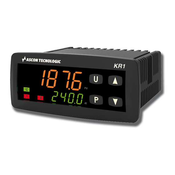
TEMPERATURE
CONTROLLER
33 x 72
KR1 model
Quick Guide • ISTR-FKR1ENG06
viale Indipendenza 56, 27029 - Vigevano (PV) - ITALIA
Tel.: +39 0381 698 71, Fax: +39 0381 698 730
Sito internet:
www.ascontecnologic.com
E-mail:
sales@ascontecnologic.com
MODEL CODE
The Hardware resources are identified by the following Model Code.
Model:
KR 1
A B C D E F G H
I
-
0 0 0 0
Line
Optional functions
None
Timer
Power Supply
100... 240Vac (-15... +10%)
24Vac (-25... +12%) or 24Vdc (-15... +25%)
Input
TC, PT100, PT1000, mA, mV, V + Digital Input 1
TC, NTC, PTC, mA, mV, V + Digital Input 1
Output OP1
Relay (1 SPDT, 4 A/250 Vac)
VDC for SSR (12 Vdc/20 mA)
Output OP2
None
Relay (1 SPST NO, 4 A/250 Vac)
VDC for SSR VDC for SSR (12 Vdc/20 mA)
HOW TO SET THE CONFIGURATION CODE
for 3 seconds
Press
to access the
configuration mode
Press
and
enter the configuration
Password 4 (default 300)
Press
and
enter c%d1 (Input Type
and Control Mode)
Press
and
to enter c%d2 (Alarms
and Service Functions)
Press
to store the
Configuration code
Note: To leave the Configuration session without
saving the settings made, press the
DECLARATION OF CONFORMITY AND
ube
MANUAL RETRIEVAL
KR1 is a panel mounting, Class II instrument. It has been
designed with compliance to the European Directives.
All information about the controller use can be found in the
Engineering Manual: ISTR-MKR_-ENG0x ("x" is the revision).
The Declaration of Conformity and the manual of the controller
can be downloaded (free of charge) from the web-site:
www.ascontecnologic.com
Once connected to the web-site, search: KR1
then click on KR1.
In the lower part of the product page (in any language) is present
the download area with links to the documents available for the
controller (in the available languages).
Warning!
- Whenever a failure or a malfunction of the device may cause
dangerous situations for persons, things or animals, please
remember that the plant must be equipped with additional
devices which will guarantee safety.
- We warrant that the products will be free from defects in material and
workmanship for 18 months from the date of delivery. Products
and components that are subject to wear due to conditions of
use, service life and misuse are not covered by this warranty.
Disposal
The appliance (or the product) must be disposed of
separately in compliance with the local standards in
force on waste disposal.
KR
1
Output OP3
None
A
Relay (1 SPST NO, 4 A/250 Vac)
-
Vdc for SSR VDC for SSR (12 Vdc/20 mA)
T
Output OP4
B
Digital I/O (see the Electrical Connections paragraph for details)
H
L
Serial Communications
TTL
C
RS485 Modbus
C
E
Terminal Type
Standard (screw type non removable terminal blocks)
D
With plug-in screw type terminal blocks
R
With plug-in clamp type terminal blocks
O
With plug-in terminal blocks (fixed part only)
E
Model Code example: KR1-HCRRRD--
-
Controller KR1, no timer, 100... 240 Vac, TC/PT100/PT1000/mV/V +
R
Digital Input 1, 3 Relay Outputs, Output 4, TTL, non removable screw
O
type terminals.
CONFIGURATION CODE
The KR1 can be easily configured by the "Code Configuration" method for the most common requirements, just entering two 4-digit
codes: Cod1 [LMNO] for the Input Type and Control Mode selection and Cod2 [PQRS] for the Alarms and the Service Functions.
For complete controller configuration see the Engineering Manual.
Note: Before starting the configuration code setting, please define and write down Cod1 and Cod2 as needed:
L M N O
User c%d1
Input Type and Range
TC J
-50... +1000°C
TC K
-50... +1370°C
TC S
-50... 1760°C
TC R
-50... +1760°C
TC T
-70... +400°C
Infrared J
-50... +785°C
Infrared K
-50... +785°C
PT 100/PTC KTY81-121 -200... +850°C/-55... +150°C
PT 1000/NTC 103-AT2 -200... +850°C/-50... +110°C
Linear 0... 60 mV
Linear 12... 60 mV
to
Linear 0... 20 mA (this selection forces Out 4 = TX)
Linear 4... 20 mA (this selection forces Out 4 = TX)
Linear 0... 5 V
Linear 1... 5 V
Linear 0... 10 V
Linear 2... 10 V
TC J
-58... +1832°F
TC K
-58... +2498°F
TC S
-58... 3200°F
to
TC R
-58... +3200°F
TC T
-94... +752°F
Infrared J
-58... +1445°F
Infrared K
-58... +1445°F
PT 100/PTC KTY81-121 -328... +1562°F/-67... +302°F
PT 1000/NTC 103-AT2 -328... +1562°F/-58... +230°F
P Q R
S
User c%d2
to
Alarm 3
Alarm 2
Alarm 1
Not used
Sensor break
High
Absolute
Low
External High/Low
Absolute High/Low
Internal High/Low
Deviation high
Deviation
Deviation low
External band
Band
key
Internal band
DISPLAY AND KEYS
Process Value
Autotune in progress (flashing)
(in eng. units)
Alarm active
Manual mode
Unit (°C/°F)
Output LEDs
Set Point (auto mode)
Output Value (manual mode)
Parameter value or State/
Function selected (editing mode)
Operator Mode
Access to:
- Operator Commands
- Parameters
- Configuration
Access to:
- Operator additional information
- Set Point
Access to:
- Set Point
Programmable key:
Start the programmed function
(Autotune, Auto/Man, Timer ...)
+
These 2 keys, pressed in sequence, allow to toggle
between MANual and AUTO modes.
ELECTRICAL CONNECTIONS
Analogue input
PV
4... 20 mA
3 wire transmitter
12Vdc
F
(note)
-
mV, V
R
O
G
D
Pt1000/NTC/PTC
H
-
S
I
TERMINALS
-
E
L
Pin:
1.4 mm (0.055 in.) max. Stripped wire: L 5.5 mm (0.21 in.)
M
q
N
Note: Terminal 4 can be programmed as:
- Digital Input (DI2) connecting a free of voltage contact between terminals 4 and 11;
- 0... 12 V SSR Drive Output (OP4) connecting the load between terminals 4 and 11;
- 12 Vdc (20 mA) transmitter power supply connecting the 2 wire transmitter between
terminals 4 and 1; for 3 wire transmitter connect terminal 4 to transmitter power supply
input and terminal 1 and 2 to transmitter signal output.
c%d1
L M N O
L
M
Control mode
OP1
0
0
H
AL1
ON/OFF heating = H
0
1
NU
AL1
0
2
C
AL1
ON/OFF cooling = C
0
3
NU
AL1
0
4
H
C
0
5
H
AL1
0
6
C
H
ON/OFF with neutral
zone (H/C)
0
7
NU
H
0
8
C
AL1
0
9
NU
C
1
0
H
AL1
PID heating = H
1
1
NU
AL1
1
2
C
AL1
PID cooling = C
1
3
NU
AL1
1
4
H
C
1
5
H
AL1
1
6
C
H
PID double action (H/C)
1
7
NU
H
1
8
C
AL1
NU
C
1
9
2
0
2
1
Note: As default, when the alarms are active, only AL1 threshold
is available at "Operator Command" level to perform non
2
2
critical tasks. To protect the AL2 and AL3 thresholds against
2
3
undesired changes, they are available only at "Parameters
2
4
list" level (password: 20). For different configurations, see
2
5
the Engineering Manual.
c%d2
P Q R S
R
Service functions activation
Q
None
Wattmeter (instantaneous power expressed in kW) (note 1)
P
Wattmeter (Power consuption expressed in kWh/h) (note 2)
0
0
0
Absolute worked time (expressed in days) (note 3)
1
1
1
Absolute worked time (expressed in hours) (note 3)
2
2
2
3
3
3
Note: 1. Wattmeter Instantaneous power is continuously computed
4
4
4
as multiplication of the Load Voltage, Load Current parameter
values and the controller output instantaneous value.
5
5
5
2. Wattmeter power consumption is the estimated hourly
6
6
6
energy consumption (using Load Voltage and Load Current
7
7
7
parameter values), computed on the previous 15 minutes
period. The readout is updated every 15 minutes.
8
8
8
3. Worked Time counter is continuously increased when
9
9
9
the controller is turned ON.
DIMENSIONS
Overall dimensions (L x H x D): 78 x 35 x 69.5 mm
Panel Cut-out (L x H):
MOUNTING
2b
Editing Mode
Confirm and go to
1
Next parameter
Increase the displayed
value/Selects the para-
meters list next element
Decrease the displayed
value or select the
previous element
Attention
Exit from Operator
commands/Parameter
The controller can be installed using 2 different types of brackets.
setting/Configuration
Follow the sequence 1, 2a, 3a for the screw bracket (collar
bracket for IP65), the sequence 1, 2b, 3b for the "butterfly"
brackets (2 pieces).
PV
4... 20 mA
2 wire transmitter
DI2
(note)
12Vdc
(note)
Thermo-
mA
couple
Pt100
OP4
(note)
OP3
Neutral Line
C
NO
Power supply
ALARM TYPES (Cod2 digits: P, Q, R)
OP2
OP3
OP4
N
O
AL2
AL3
0
0
0
1
AL2
H
0
2
AL2
AL3
0
3
AL2
C
Absolute
High
0
4
AL2
AL3
0
5
Absolute
AL2
C
Low
0
6
AL2
AL3
0
7
AL2
C
0
8
AL2
H
0
9
AL2
H
1
0
AL2
AL3
1
1
AL2
H
1
2
AL2
AL3
1
3
AL2
C
1
4
AL2
AL3
1
5
AL2
C
Absolute
1
6
AL2
AL3
External
1
7
AL2
C
Absolute
1
8
AL2
H
Internal
AL2
H
1
9
Deviation
High
Deviation
S
Low
0
1
2
3
4
(3.07 x 1.37 x 2.73 in.)
71 +0.6 x 29 +0.6 mm
(2.79 +0.023 x 1.14 +0.023 in.)
2a
3a
3b
3a
2a
2b
3b
1
RS485
DI1
OP1
OP2
C
NO
C
NC
NO
Supply voltage: 100... 240 Vac/
18... 28 Vac/
20... 30 Vdc
Absolute Alarm
PV
Time
ON
ON
ON
Absolute High-Low Alarm
PV
Time
ON
ON
ON
ON
Deviation Alarm
PV
Time
ON
ON
ON
Band Alarm
PV
Time
ON
ON
Band
Internal
ON
ON
ON
Band
External
Advertisement

Related Manuals for Ascon tecnologic KR1


Summary of Contents for Ascon tecnologic KR1
- Page 1 CONFIGURATION CODE The KR1 can be easily configured by the “Code Configuration” method for the most common requirements, just entering two 4-digit codes: Cod1 [LMNO] for the Input Type and Control Mode selection and Cod2 [PQRS] for the Alarms and the Service Functions.
- Page 2 PARAMETERS SETTING Parameters List (PASS: 20) (in gray the parameters related to optional features) User Group Param. Description Range value or selection list elements Default Note value Password 2 tr. S t Timer status Option (default: 20) Access to Auto, parameters oPEr Operative Mode Selection oplo Manual,...
Need help?
Do you have a question about the KR1 and is the answer not in the manual?
Questions and answers