Table of Contents
Advertisement
Advertisement
Table of Contents

Related Manuals for Philips Strand Lighting 100 plus series


Summary of Contents for Philips Strand Lighting 100 plus series
-
Page 2: Strand Lighting Locations
Fax: + 852 2757 1767 The material in this manual is for information purposes only and is subject to change without notice. Philips Strand Lighting assumes no responsibility for any errors or omissions which may appear in this manual. For comments and suggestions regarding corrections and/or updates to this manual, please visit the Philips Strand Lighting web site at www.strandlighting.com or contact your nearest Philips Strand Lighting office. -
Page 3: Important Information
Philips Strand Lighting Limited Two-Year Warranty Philips Strand Lighting offers a two-year limited warranty of its products against defects in materials or workmanship from the date of delivery. A copy of Philips Strand Lighting two-year limited warranty containing specific terms and conditions can be obtained from the Philips Strand Lighting web site at www.strandlighting.com... -
Page 4: Table Of Contents
TABLE OF CONTENTS Strand Lighting Locations ....................Inside Front Cover IMPORTANT INFORMATION Warnings and Notices............................1 Additional Resources for DMX512......................... 1 Philips Strand Lighting Limited Two-Year Warranty..................1 TABLE OF CONTENTS PREFACE About this Guide..............................3 Product Description ..............................3 Compliance Information............................ -
Page 5: Preface
100 Plus Series Console PREFACE 1. About this Guide The document provides installation and operation instructions for the following product: • 100 Plus Series Console Please read all instructions before using this product. Retain this manual for future reference. Additional information for Strand Lighting control consoles including product descriptions may be downloaded at www.strandlighting.com 2. -
Page 6: 100 Plus Series Console Layout
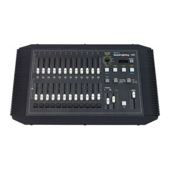
Operations Manual INTRODUCTION 1. 100 Plus Series Console Layout Figure 2 illustrates the layout of the control features of the 100 Plus Series Console. Effect Forward / Memory Record Channel LED Fade Time / Effect Reverse / FX Speed Rotary Memory Advance 1 Channel Fader LED Display... - Page 7 100 Plus Series Console Channel Faders A fader that controls the output of the corresponding dimmer number. Fader Flash Button A momentary button that flashes the level of the corresponding fader to full. Which fader is corresponding depends on the setting of the FLASH BUTTON. See below. Mode Button A button that toggles between the three modes of operation of the console.
-
Page 8: Getting Started
Operations Manual LED Display This will show alpha / numeric information about the console. Such as fade time, effect step rate, memory number and whether the black out button is active. LED Lights All channel faders have LEDs that mimic the output level of each fader. LEDs also are indicators of the channel mode as well as when all features are activated. -
Page 9: Connecting Dmx512
4. Rack Mounting If you wish to mount the 100 Plus Series Console in a rack, using a Philips screwdriver, remove the hardware securing the four side pieces around the console. Use the eight mounting holes (as shown in Figure 5) to secure the console in a rack. -
Page 10: Product Care
Operations Manual 5. Product Care The 100 Plus Series Console requires very little care and does not have any user-serviceable parts. Avoid spilling liquid on the equipment If this should happen, switch the equipment off immediately at the mains. To reduce the risk of fire or electric shock, do not expose the equipment to rain or moisture. -
Page 11: Console Operation
100 Plus Series Console CONSOLE OPERATION 1. Two Scene Operation When the console is powered up, check the Mode LED indicators to determine the operating mode it is in. Press the Mode button as necessary to place the console in Two Scene Mode. The "Two Scene" LED will illuminate to confirm that the console is in two scene mode as shown in Figure 6. -
Page 12: Timed Crossfades
Operations Manual 3. Timed Crossfades For timed crossfades - use the same procedure as the manual crossfade but with the fade timer set to the preferred fade time. The LED display will show the fade time that is set. Timed crossfades can vary from 0 (Manual) to 15 minutes. -
Page 13: Hold
100 Plus Series Console 5. Hold In single scene mode only, using the HOLD button (as shown in Figure 10) allows the operator to freeze all dimmer output and manually reset the levels for all 24 faders to create a different look. RECORD PREVIEW Hold Button... -
Page 14: Effect - Two Scene Mode
Operations Manual Press one of the Effect buttons - Forward, Reverse, Random, or Bounce. Manual 5min. FORWARD REVERSE RANDOM BOUNCE Effect Buttons RECORD PREVIEW H OLD MODE FLASH DE L TWO SCENE SINGLE SCENE CH 1-12 MEMO RY CH 13-24 Figure 11: Hold Button - Single Scene Mode Table 3 provides details of each Effect Button’s operation. -
Page 15: Memory Operation
100 Plus Series Console 8. Memory Operation Memory mode allows you to program a cue stack of up to 99 memories. These can be played back sequentially. In memory mode the buttons labeled in blue will be available. 2.5s 1.5s BLACKOUT 3min. -
Page 16: Playback Mode
Operations Manual Playback Mode After recording cues into the console memory, you can play them back. There are two methods, one using the GO button (Flash Mode Button) and the other using the Preset Master A and Preset Master B. Go Button Playback Use the [ + ] button to take you to the memory that you wish to begin with. -
Page 17: All Memory Deletion
100 Plus Series Console Press the DELETE button for 2 seconds. This will delete the currently selected memory it will change from an "SP" to "SS". You can continue to the next memory you wish to delete. All Memory Deletion Select Record function by pressing the RECORD button while holding down the MEMORY button. -
Page 18: Technical Specifications Electrical
Operations Manual TECHNICAL SPECIFICATIONS 1. Electrical Supply Voltage: Universal power supply 90-240V Approvals: CE marked with UL listed and cUL power supply Connectivity: 1 DMX512 Out (XLR5F) port 2. Mechanical Construction: Rigid folded sheet steel and Flame retardant ABS controls Operating Temperature: 0°... - Page 19 100 Plus Series Console NOTES Mechanical...