Table of Contents
Advertisement
Quick Links
Advertisement
Table of Contents

Summary of Contents for Gunnebo SpeedStile BP DS Wide Lane
- Page 1 series P E E D T I L E Operation & Maintenance Manual...
- Page 3 Document History Author/ Rev. Date Checked/ Description Page Section Approved. 27/03/2014 DGK/MRP/KT First Edition manual...
-
Page 4: Table Of Contents
Contents Page Section 1 Introduction •General •Electrical Warnings •Errors •Proprietary Notices •Hardware Changes •Rotating Machinery •Warnings, Cautions and Notes •Warnings •Cautions •Notes •Static Sensitive Devices •Good Practices •Equipment Safety Systems •CE - Marking Section 2 Product Description •Passage Management •Dimensions and Weights Section 3 Instructions For Use •Using the SpeedStile BP DS... - Page 5 •MB01 Motor Driver board: •Motor Control •MB01 Trimmers •Trimmers Description •TR1: Running Mode Selection •TR2-TR6 : Setting •Learning Procedure •Zero Setting Cycle and Rest Positioning •Mechanism Speed •Safety Photocells Management •Introduction •Increasing the Safety Area •How Does the Safety Area Works •Safety Management in Running Mode •Opening Doors •Safety Area...
- Page 6 •Launching the Learning Procedure •GC01 Human Interface •GC01 Real Time Messages •GC01 Fraud Alarm Messages •Menus •Menu Items •Sub Menu Items •Parameter Item •Function Item •Main Menu •Versions Menu •View Aisle Utility •Out of Service LCD messages •Maintenance Menu •Open / Close test •Repeated Open/Close Cycle •Battery Test •Buzzer Test...
- Page 7 •Connection to RS485 Serial Line •Remote Control Connection •Emergency Control Connection •Card Reader Connection •Customer Connections •Commissioning Section 6 Maintenance •General Care •Routine cleaning, all finishes •Stubborn stains and discolouration, all finishes •Oil, Grease marks, all finishes •Rust and other Corrosion products, Stainless finishes •Minor scratches on painted surfaces •Deep scratches on painted finishes causing rust •Routine Maintenance...
- Page 8 Section 9 Declaration of Conformity •Declaration of Conformity...
-
Page 9: General
E-mail Turnsupport.entrancecontrol@gunnebo.com Proprietary Notices All data appearing herein is of a proprietary nature, with exclusive title to it held by Gunnebo Entrance Control Ltd. The possession of this Manual and the use of the information are therefore restricted only to those persons duly authorised by Gunnebo Entrance Control Ltd. -
Page 10: Hardware Changes
Hardware Changes No hardware changes may be made without authority from Gunnebo Entrance Control Ltd who will be responsible for ensuring that the proposed change is acceptable in all safety aspects. Personnel authorised by Gunnebo Entrance Control Ltd may only make hardware changes. -
Page 11: Equipment Safety Systems
When working on the equipment, remove any personal jewellery that may be conductive, or clothing that may become entangled with mechanical parts. Equipment Safety Systems Safety systems and controls, such as interlocks, covers and guards, must not be overridden or bypassed by personnel other than authorised staff who are qualified to carry out prescribed actions within specified Warnings. - Page 12 Hazard Fume Inhalation Current Controls Compliance with COSHH regulations Rating 5: Commissioning Who is at Risk Site Engineer Hazard Power Supply/Moving Parts Current Controls Isolate Power Rating 8: Floor Drilling Who is at Risk Installation Engineer Hazard Flying Debris and Noise Current Controls Protective Equipment must be worn Glass Panel Installation...
-
Page 13: Product Description
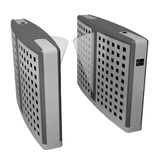
Section 2 Product Description The SpeedStile BP DS range is designed for applications with a low profile, and high flow rate and still maintaining a high degree of security. The SpeedStile BP DS is the premium unit in the SpeedStile BP DS range. The customer has the option of various 3M vinyl finishes on the panels and centre strip as well as the plinth. - Page 14 SpeedStile BP DS Wide Lane...
-
Page 15: Passage Management
Passage Management The command logic manages all of the system actions that allow a person to move through the passageway. The logic uses information from photocells to detect the presence and position of persons within the passageway area. In addition, it receives authorisation signals from the card readers and at the same time, provides the readers with activation and transit completed signals. - Page 16 an abnormal conditions and activates a series of operations aimed at protecting the user. Method of Operation: On receipt of a signal from the access control system, or push button, the wings will open. If an unauthorised person attempts to tailgate or tries to enter from the opposite direction, the system detects and closes the unauthorised passage and activates an alarm.
-
Page 17: Dimensions And Weights
Dimensions and Weights Dimensions are in mm and net weight is in Kg. Weight(kg) Overall Passage Cabinet Cabinet Cabinet Side Centre Height Width Height Length Width * Cabinet Cabinet Standard 1448 Short Wide Short 1448... -
Page 18: Instructions For Use
Section 3 Instructions For Use Using the SpeedStile BP DS The SpeedStile BP DS is unlocked by presenting a personalised identity card or device to the access control reader, (Supplied by others). It can also be unlocked by depressing a button on the casework or remote reception push button, if fitted, enabled for Free Passage. -
Page 19: Safety
Safety The SpeedStile BP DS passage is protected via a safety photocell so that when a presence is detected the panels will not operate until the presence is removed. In this condition the SpeedStile BP DS may be go into Out Of Service Mode. Should an obstacle be detected during the closing of the panels they will back off to the open position. -
Page 20: Passage Management
mode assumed by the gate at the start up, waiting for the serial line configuration command (see “Transit Group” in the annex “Parameter Table”). The mode change is possible only if the gate is in stand-by condition: the gate shall not be engaged, in alarm or in emergency conditions. -
Page 21: Programmable Parameters
The alarm signal continues until the cause which generated it is removed. The activation of the alarm signal output relay could be delayed by means of a programmable parameter. The flashing frequency of the traffic lights and pictograms can be regulated by means of a programmable parameter. -
Page 22: Technical Information
Section 4 Technical Information Motor Board Maintenance & Setup The MB01 board allows operation in two different states: Running mode and Maintenance mode. In Running mode, the board is under the control of the GC01 logic control board which, through the CAN bus, commands the opening and closing of the doors. In Maintenance mode, the board is logically detached by the GC01 control board and the operator can set the working parameters such as the speed, offset, centre position, learning cycle, and can also move the doors through three push buttons, mounted on the card. -
Page 23: Mechanical Stop Adjusting
Mechanical Stop Adjusting Adjusting of the mechanical stop at the limits of the stroke in order to have the locked or the unlocked configuration in case of power failure Fig 4.1 Tuning Locked/Unlocked The different modes, in the case of power failures are defined by the different position of the mechanical stops: this can force the mechanism arm to be above the centre line of the mechanism (see figure). -
Page 24: Optional Tools
Optional Tools Battery Back up For SpeedStile BP DS ranges, to allow the power down management, there is an optional extra Battery Back up configuration which is capable of providing 2A/h sufficient to guarantee the doors opening/closing in case of several power down sequence for all door sizes in the range. The final position of the doors depends on a parameter (for more details see “Alarm Parameters”... -
Page 25: Control Logic
Control Logic The control logics are distributed between two panels (master and slave) allocated into the two cabinets that define the passageway. Figure 4. 2 – Control Logic Panels Master Panel Slave Panel Fig 4.2 Table Service counter Buzzer MB01 motor driver GC01 gate controller Main circuit breaker Transformer... -
Page 26: Gc01 Gate Controller Board
GC01 Gate Controller board: This is the CPU (Central Processing Unit). Control of the entire gate is done here. The logic is controlled by a microprocessor. The GC01 controls the detection system that recognizes the presence of passengers inside the gate manages time outs and gives the opening and closing command to the panel mechanisms. -
Page 27: Mb01 Trimmers
Fig 4.3 – MB01 Board Layout MB01 Trimmers The MB01 board has six trimmers (see Figure 4.3) which allow the tuning of the door movement. Each trimmer has six snap positions (0-5). Trimmer Description Running mode selection Closing speed (5 = max speed) Opening speed (5 = max speed) Obstacle detection sensitivity (0 = max sensitivity) Close position offset (5=highest distance from end... -
Page 28: Trimmers Description
Trimmers Description or the poSItIonS from are requIred for certaIn condItIonS f thoSe condItIonS are not preSent after reSet the Board wIll Be In an error condItIon SIgnalled By the dISplay aS Showed Below After MB01 reset, if TR1 is in position 0-4, this is an error condition: the mechanism is not yet selected! -
Page 29: Tr2-Tr6 : Setting
TR2-TR6 : Setting TR2 – TR3- the gate panel speed can be regulated with these two trimmers on the MB01 board, TR2 trimmer is for the closing speed and TR3 is for the opening speed. Each trimmer has six different settings available (for more details see the section “Mechanism Speed”). -
Page 30: Mechanism Speed
Every time the gate is powered, the MB01 needs to make this zero setting before being able to move normally. The process will be done in Running Mode and not in Maintenance Mode as in the former. The logic interrupts the zero setting cycle if: •... -
Page 31: Safety Photocells Management
Safety Photocells Management Introduction The SpeedStile BP DS is equipped with either one or (optional) two safety photocells which, are installed in between the doors, to prevent the user from being hit by the panels when closing. Fig 4.4 – Safety Photocells Disposition Safety RX1 Increasing the Safety Area The user is able to program several transit photocells so that they also act as safety photocells,... -
Page 32: How Does The Safety Area Works
Fig 4. 5 – Adding Safety Photocells Dialogue < < RESET In the figure above is shown the dialogue menu to set the safety pattern. With the keys SW2 and SW3 the user can point to a particular photocell (indicated by an arrow); after pointing to a photocell the user can add or remove that photocell to the safety pattern by pressing the SW1 key. -
Page 33: Opening Doors
Opening Doors • If the Open Safety parameter is ENABLED and the safety photocells are engaged, the Gate shuts down the motor power making it possible to move the doors. • If the Open Safety parameter is DISABLED, the Gate opens the doors anyway. The parameter “Open Safety” is the same for the Standard and Wide Gate. The parameter “Open Safety” is the same for the Standard and Wide Gate. Safety Area When the gate is out of running mode there are several cases in which the doors could move: •... -
Page 34: Transit
That redundant protection is bypassed when the B12 copper jumper is cut off (see “Table: MB01 Jumpers Factory Setting” - Appendix B). Transit Introduction The command logic manages all the system actions, which allows a person to move through the passageway. The logic uses all the in-formation from the photocells to detect the presence and position of persons during the transit. -
Page 35: Validation
Table For Hold Open/Close MBO1 M5 - M4 Hold Open / Close Connection M5 Terminal M4 terminal details Hold Open + +24Vdc Users control Linked pins Hold Close - -24Vdc Users control Linked pins Validation In this case, the user must validate within a time out period that depends on which corridor zone is engaged. - Page 36 Figure 4.6 – Example of Zones Configuration If “Access Level”, for example, is programmed as “4”: • Zone 1- sensor 1, 2 and 3. • Zone 2- no sensors. • Tailgating disabled. If the doors are closed and passenger engages the Zone 1/2 sensors and the Zone 1/2 time out elapses, the Control Logic signals an intrusion and the display flashes;...
- Page 37 Fig 4.7 – Approaching a FREE-Mode Aisle Dir.A - • flags table marked yellow those flags chaNged above ScenarIo • Pcw' ‘g ” questIoN mark racer INdIcates reeN rrow ‘r ’ eader ross eader • ePeNds ccess mode related sIde When a user approaches point A (blue line) the doors open and the aisle be-comes busy in B direction.
- Page 38 Fig 4.8 – Door’s Crossing a FREE-Mode Aisle Dir.A When the user passes the door line and reach point B (blue line) a special timer is started, when this timer expires the door will be closed if no other users with permission are approaching the aisle.
- Page 39 Fig 4.9 – Leaving a FREE-Mode Aisle Dir.A When the user exits the gate after point D (blue line) the gate remains busy in direction A until a programmable timer expires. When this timer is expired the gate becomes available for the passage in the opposite direction (if allowed).
- Page 40 Fig 4.10 – Gate Appearance when in BLOCKED Mode When the access mode is blocked in a given direction that direction is forbidden for any passage except in the case of a Single passage permission provided by the serial protocol. The PCW's show a red cross and the casework LEDs show red.
-
Page 41: Controlled Access Mode
Controlled Access Mode When people approach the gate in a direction programmed as Controlled, to cross the walkway they need a permission signal provided by the reader interface input. To prevent any fraud attempt the gate provides a series of fraud algorithm (see section “Fraud Alarms Selectivity”) capable to detect different fraud scenarios. -
Page 42: Readers Input Programming's
The Readers can be enabled or disabled by parameters: • Main-menu/Setup/Reader/Reader A status for Reader A. • Main-menu/Setup/Reader/Reader B status for Reader B. If the Reader is disabled the User will not be able to validate. If the Reader is ENABLED the status of the Reader will depend on several conditions. The actual status of the Readers in any moment will be indicated by two flags: •... - Page 43 After a correct validation on the Reader A, the flag Ack reader A will pulse. After a correct validation on the Reader B, the flag Ack reader B will pulse. The pulse time is a parameter: Main-menu/Setup/Reader/Passage ack pulse.
-
Page 44: Events Involved In A Controlled Access
Events involved in a Controlled Access Fig 4.11 – Validation Process in CONTROLLED Mode Dir.A The User approaching the gate validates the ticket to get the permission and the validation should be made in the Zone 1. The Tracer LED and casework LEDs acknowledges the event showing a green for a while (timed or position dependent). - Page 45 Fig 4.12 – Doors Crossing in CONTROLLED Mode Dir.A The doors crossing event is determinant in the whole process of the transit in Controlled mode and fraud detection. The stack is decremented and if equal to zero, no other user is allowed to enter the gate.
-
Page 46: Priority
Flags Value Ack reader B Power fail Fig 4.13 – Leaving the Aisle in CONTROLLED Mode Dir.A When the User leaves the Aisle the gate will go into a standby state ready to manage a new transit. Flags Value Reader A enable Reader B enable Ack count A Ack count B... - Page 47 Access Mode Priority Priority Scenario Side A Side B Free Any scenarios Blocked Any scenarios The Aisle is free, the stack B is 0, Free and A engage the aisle Controlled The Aisle is free and B validate or B engage the Aisle Free Any scenarios...
-
Page 48: Transit Authorisation For User With Limited Mobility
Transit Authorisation for User with Limited Mobility A specific input is available for each direction to allow the transit of a passenger in a wheelchair. This input works like the reader permission input but, when it is activated, the gate logic configures all time-outs and parameters for that kind of transit managing. -
Page 49: Alarm Description
Alarm Description Tailgating It indicates that someone is attempting to go through the passageway without authorization following an authorized person. Because of the key role of this feature in security Controlled mode and its impact on the transit flow, the user can select its value to adjust the velocity to detect the tail scenarios. In particular the user can select the sensitivity with the parameter “Access Level”: •... -
Page 50: Interface Inputs And Outputs
Interface Inputs and Outputs The SpeedStile BP DS provide twelve inputs each one programmable to be ad-dressed to one of the Reader's triggers. To obtain the most flexible signals, interface from the SpeedStile BP DS toward the ticket readers and surrounding systems. The logic offers a wide set, of electric inputs and outputs. A logic function attributed to each one of these can be set with values on corresponding programmable parameters (see “I/O Group”... -
Page 51: Gc01 Addressable Inputs
GC01 Addressable Inputs M6 ‘NPN RELEASE’ Operation (*) Electrical Characteristics reader B authorisation rated input voltage 5 VDC; 3 mA @ 0 VDC reader B authorisation - wide rated input voltage 5 VDC; 3 mA @ 0 VDC M5 ‘OPTOCOUPLED RELEASE’ Operation (*) Electrical Characteristics rated input voltage 24 VDC;... -
Page 52: Mb01 Addressable Input
Fig 4.15 – MB01 Addressable Inputs (M6 – M7) and Outputs (M8) MB01 Addressable Input M7 ‘READER NPN IN’ Master Side Slave Side Electrical Operation (*) Operation (*) Characteristics rated input voltage 5 VDC; reader A authorisation reader B authorisation 3 mA @ 0 VDC rated input voltage 5 VDC;... -
Page 53: Mb01 Addressable Outputs
M6 ‘READER OPTO IN’ rated input voltage 24 VDC; reader A authorisation reader B authorisation 11 mA @ 24 VDC - wide - wide MB01 Addressable Outputs M8 ‘READER OUT’ Master Side Slave Side NC/NO Signal (*) Signal (*) Relay Jumper 1, 2 Gate Busy A... -
Page 54: Output Relays Programming
For example: if a given input is programmed to be “WIDE READER –B-“, when properly signalled, the stack of Reader B interface will be incremented and any passage in direction B until the stack reaches zero will be treated as Wide passage. Output Relays Programming Introduction The SpeedStile BP DS provides a total of 15 programmable relays:... -
Page 55: Relays Programming
Flags Meaning Signals when the logic detects an Intrusion in Fraud_Intr_B: the direction B Signals when the logic detects a Wrong way Fraud_WW_A: and the correct passage is in direction A Signals when the logic detects a Wrong way Fraud_WW_B : and the correct passage is in direction B Signals that a passage timeout expires and the Timeout_A:... -
Page 56: Emergency
Relay Motor Board / Slave Side K1 Main-menu/Setup/IO/Slave Board/Conn:M8 Pin:5,6 Relay: K1 K2 Main-menu/Setup/IO/Slave Board/Conn:M8 Pin:7,8 Relay: K2 K3 Main-menu/Setup/IO/Slave Board/Conn:M8 Pin:3,4 Relay: K3 K4 Main-menu/Setup/IO/Slave Board/Conn:M8 Pin:1,2 Relay: K4 Control Board K1 Main-menu/Setup/IO/Control Board/Conn:M3 Pin:3,4 Relay: K1 K2 Main-menu/Setup/IO/Control Board/Conn:M7 Pin:7,8 Relay: K2 K3 Main-menu/Setup/IO/Control Board/Conn:M7 Pin:5,6 Relay: K3 K4 Main-menu/Setup/IO/Control Board/Conn:M3 Pin:1,2 Relay: K4 K5 Main-menu/Setup/IO/Control Board/Conn:M3 Pin:5,6 Relay: K5... -
Page 57: Electrical Input
Electrical Input The MAIN emergency input of the logic is located on the GC01 board M4 connector. With the W12 jumper (in, the input is drivable by dry contact or npn open collector. If that jumper is off, the input is opto isolated, 24 VDC voltages is required. Extra emergency inputs can be programmed setting the Inputs in the Setup/IO/…/…... -
Page 58: Special Functions
When the parameter Main-menu/Setup/Serial 485/Enable is set to “DISABLED”, then the access mode will be set by the Remote Interface .The remote interface is a set of Electrical digital Inputs whose combination determines the access mode settings (see the annex “Parameter Table”). Operation modes are set by means of specific inputs on the GC01 board. -
Page 59: Mb01 Messages And Leds
MB01 Messages and LEDs The MB01 logic signals is operating status by means of the LEDs and the 7 segment display mounted on board. Door in target position Opening command is being executed Zero setting cycle has not been executed Safety zone engaged during zero setting cycle Detected obstacle Closing command is being executed... - Page 60 Display Meaning Appears in case of power fail. When the MB01 switches off, appears: Failure of some device into the motor control circuit. After MB01 reset, if TR1 is in position 0-4, this is an error condition: the mechanism is not yet selected! After MB01 reset, if TR1 is in position 0, this is an error condition.
-
Page 61: Mb01 Maintenance Mode Operation
Description Green on when 42V voltage is present. Green on when 24V voltage is present. DS10 Green on when 5V voltage is present. DS11 Green on when 12V voltage is present. DS12 Green on when K1 coil is activated. DS13 Green on when K2 coil is activated. -
Page 62: Checking The Mechanism Movement
When in MB01 maintenance the board is disconnected from the Gate Controller and will no longer answer or execute any commands coming from the Controller, the control board goes into stand-by and displays: M A I N T E N A N C E S L S T A N B Y RESET M S:... -
Page 63: Launching The Learning Procedure
MB01 displays If the switches S2 / S4 are used and the “Learning Procedure” has not been run before the door close/open the MB01 starts the “zero setting procedure”. With button S3 the MB01 starts the learning procedure (for more details see section “Launching the Learning Procedure”). -
Page 64: Gc01 Human Interface
Learning cycle: The MB01 executes several opening/closing cycles in order to record the motor current slopes due to the trimmer’s settings. This step is marked by the display with: Then the MB01 comes back into maintenance mode. tr4 – f one of the trImmer poSItIonS are changed except for oBStacle detectIon SenSItIvIty It IS neceSSary to redo the zero SettIng... -
Page 65: Gc01 Fraud Alarm Messages
R U N N I N G M O D E : F R E E N C C T R L RESET Direction B Aisle Direction A Mode Mode Mode I O mode selected by acknowledgement I O PARAMETER SERIAL LINE* Example: R U N N I N G M O D E :... -
Page 66: Menu Items
Each menu is comprised of Sub-menus, functions, parameters and string items, they can be displayed either as Multi- Line or Single-Line items. In the case of Multi- Line menu, the display shows one item at a time and that item could occupy both lines of the display;... -
Page 67: Parameter Item
In the previous picture the Single-Line <Main Menu> shown on the top line the sub-menu message Maintenance; if you now press the Enter key you’ll enter the Multi- Line <Maintenance> sub menu. > O P E N / C L O S E T E S T RESET Parameter Item The parameter item allows you to set a particular parameter on the system;... -
Page 68: Function Item
with value strings {“NC”,”NO”} at the moment set to “NC”. To modify the value, you have to press enter in correspondence of the parameter you want to change. The parameter “NC” value will start to flash. Use up (SW2) button or Down (SW3) button to change the value, then press the Enter (SW1) button to confirm or Esc (SW2+SW3) to retain the original value. - Page 69 To select the desired choice by, pressing SCROLL UP until you see your choice on the top row. Then select with the ENTER (SW1) Button. For example, to enter into Maintenance menu: Press ESC (SW2 + SW3), the display shows >...
-
Page 70: Versions Menu
Each menu may contain sub menus. Follow the same logic to navigate through the menus and sub menus: ENTER to access the sub menu, ESC to exit to the higher level menu. Versions Menu Path: Main menu / Version The display shows the codes of the firmware currently loaded into the GC01 and MB01 boards. The message starts with ‘CB’... -
Page 71: Maintenance Menu
Board Message Description One of the passage detection system sensors Obscured sensor engaged for more than a fixed time Check the View aisle menu to confirm sensor. One or more sensors weren't obscured as expected Sensors not engaged after a transit. On/off test fail The safety sensor test has failed. -
Page 72: Open / Close Test
Open / Close test Path: Main menu / Maintenance / Open-Close test The display will show: A L L M A S T E R S L A V E RESET closed. open. moving or not defined status. The open or close command can be given to each door by pressing the corresponding button: For both doors. -
Page 73: Buzzer Test
information about the charging status. The display will show different information depending on the batteries status and their pending operation: To update the charge level, press the push button SW2. The battery will then be shorted on a resistor for 10 seconds. During this time, the charge value is read and at the end of the test, the display will show the actual charge level for both Master &... -
Page 74: Pcw Test
PCW test Path: Main menu / Maintenance / Traffic lights test The display will show: C U R R E N T : R E D R E D G R N B A D G E RESET • When button SW1 is pressed, the PCW's will show their respective red crosses. -
Page 75: Setup Menu
Setup Menu This menu gives the user access to the programmable parameters that affect the management of the passage detection system, door movement, time outs and interface signals from/to the external world. Refer to the ‘Parameters Programming Manual’. Automatic Testing The logic system of the Unit performs a looped test of the operating status of the motors, photocells and batteries (if installed). -
Page 76: Automatic Accident Prevention Photocell Testing
electronic circuit cuts the power and the motor board goes in fault; in this condition to restore a normal operation a power-off/power-on of the board is required. If any of the previous anomalies are detected by the diagnostic, the Motor Board goes in fault condition, showing an “F”... -
Page 77: Automatic Battery Testing
The diagnostic of the Gate Controller monitors if a photocell, after five consecutive transits, results in the photocell not being obscured. This test is able to detect if a photocell is “shorted” but requires more time respect to the others tested. Automatic Battery Testing The SpeedStile range can make use of batteries (see section “Backup Batteries”) to open the doors in case of power failure (optional extra). -
Page 78: Installation
Gunnebo Entrance Control. Retain all major component packaging for re-use in the event that items may need to be returned for servicing during their life. -
Page 79: Environmental Conditions
Environmental conditions For the correct operation of the equipment the site should meet the following requirements: Working temperature: from +5° to + 40 °C. Humidity must not exceed 95%. The SpeedStile BP DS must be installed indoors out of rain and any water sprays, since it is not protected from dangerous effects of water penetration. -
Page 80: Ds Containment/Layout Details
DS Containment/Layout Details... -
Page 82: Removing Panel
Removing panel The SpeedStile BP DS has unique panels made from a tough material called PET-G (Polyethylene terephthalate), making it stronger and more flexible than the traditional laminated glass used on the BA and EV Speedstiles. The new panels may also be customised to suit the users design needs. The panels are still secured by two barrel locks , but to ensure no damage is incurred to the panels please follow this step by step guide. - Page 83 Step 1a- Cut away showing locking cam . Step 2- Supporting the panel shown my the red circles , prepare to lift off.
- Page 84 Step 3- Lift panel Step 3a-Detail of panel lifting clear of locating pins.
- Page 85 Step 4- Lift panel clear carefully, and place in a safe place.
-
Page 86: Cable Layout
All cables and conduits are to be supplied by client and installed prior to installation. Gunnebo provides the interconnection 230VAC cable and the CAN bus cable. For units that are to be controlled by Card Access or similar it is recommended that Gunnebo Entrance Control Technical Personnel are advised prior to starting the installation routines. - Page 87 The following cables generally connect the SpeedStile BP DS: Power Supply Cable For each door a power supply cable with 3 conductors must be used, starting from the user switch gear and running to the power supply unit terminal block (Phase, Neutral and PE conductors).
- Page 88 Fig 5.1 – SpeedStile BP DS General Lane Configuration Installation Secure Side Master Installation Non Secure Side Slave Left cabinet Centre cabinet Right cabinet Installation Secure Side Master Installation Non Secure Side Slave Left cabinet Right cabinet...
-
Page 89: Unit Positioning
Unit Positioning The following details should be noted, when planning the location of the SpeedStile BP DS unit. • Allow 50 mm to the rear of the SpeedStile BP DS to enable removal of the side access panels. Floor Drilling The following guidelines are given to ensure that the unit is positioned correctly. • Mark the floor fixing positions carefully as shown on the appropriate illustration and check the conduit risers are correct. •... -
Page 90: Setting To Work
Setting to Work Bp dS peed tIle caBInet IS generally SupplIed aSSemBled and only requIreS to Be anchored to the floor n SpecIal caSeS the cceSS anelS are to Be fItted after the InStallatIon This is of maximum importance for the system to operate properly •... -
Page 91: Card Reader
Card Reader A card reader mounting plate is included within all SpeedStile BP DS units. Drilling details will need to be completed on site to suit each particular type of card reader. Follow the below step by step guide on removing the card reader plate. Home position of card reader plate Step 1- remove fixing as shown. - Page 92 Step 2 - Rotate the plate downwards using the rolling pins.
- Page 93 Step 3 - Remove plate.
-
Page 94: Electrical Connections
Electrical Connections he followIng routIneS muSt Be carrIed out By a qualIfIed electrIcIan Master - Slave Connection Before to connect the mains power, operate the connection of the master-slave signal and power cables. • Connect the CAN BUS cable between the Master and Slave using supplied terminal connection blocks. • Connect the power supply cable between the Master and the Slave. Fig 5.2 – Master – Slave Connection – CAN Bus Cable Power Supply Connection •... -
Page 95: Earth Connection
Fig 5.3 – Master – Slave Connection – Power Cables Earth Connection An efficient earth connection is essential for safe operation of the entrance gate. Make sure that all metal parts of the gate are grounded. Connection to RS485 Serial Line If the system is to be equipped with an RS485 serial line, connect the data transmission line to the corresponding terminals on the master logic panel. -
Page 96: Commissioning
Commissioning Power on the unit switching on the main circuit breaker and exit from the aisle. The doors start the closing movement and go in closed position. After a couple of seconds the unit goes in running mode or signals a fault condition if a problem is en-countered in the start-up phase. -
Page 97: Maintenance
Section 6 Maintenance General Care Access to the electrical installation is strictly reserved to maintenance technicians authorized by Gunnebo Entrance Control. "0" ll the maIntenance procedureS muSt Be carrIed out wIth the maIn SwItch at the poSItIon unleSS otherwISe IndIcated “... -
Page 98: Minor Scratches On Painted Surfaces
Although the software of the gate logic already foresees a control of the batteries state, Gunnebo Entrance Control recommends checking the state of the batteries annually. In order to check them manually, you have to execute the following operations: •... -
Page 99: Angular Sensor
Please note that Gunnebo Entrance Control recommends replacing the batteries every 3 years. Angular sensor For all the mechanisms but excluding the Wide Fail Safe model. Gunnebo Entrance Control recommends replacing the angular sensors after 10,000,000 doors opening and closing cycles usage. -
Page 100: Cables And Connectors
F1 = 5x20 10A 250V Time delay; protection on the +42V power supply line F2 = 5x20 2.5A 250V Time delay; protection on the +24V not regulated circuit F3 = 5x20 10A 250V Time delay; protection of the supply circuit from battery F4 = 5x20 2.5A 250V Time delay;... -
Page 101: Test Points
Test Points +24V green LED: on when 42V voltage is present green LED: on when 24V voltage is present DS10 green LED: on when 5V voltage is present DS11 green LED: on when 12V voltage is present... -
Page 102: General Component Maintenance
General Component Maintenance Ensure the assembly is kept clean. GC01 Board Replacement pcB, efore removIng the record the poSItIon of the umperS SwItcheS and onnectorS • Disconnect the power supplies. • Remove all connectors from the PCB. • Replace the PCB. • Configure the jumpers and dip-switches on the new PCB. • Reconnect the cables and connectors. • Reconnect the power supplies. • Switch ON the Unit and return it to normal operation. MB01 Board Replacement pcB, efore removIng the record the poSItIon of the... -
Page 103: Battery Replacement
Battery Replacement: This operation must to be undertaken by personnel authorized by Gunnebo Entrance Control. The SpeedStile BP DS must be disconnected from the mains power supply be-fore the batteries are replaced. Both batteries should be replaced. Positioning and connection:... -
Page 104: Fault Finding
Fault Finding During normal operation, the main control logic GC01 displays a collection of messages regarding the normal status or the fault conditions. To read the messages displayed by the GC01 is the first check to do in case of failure of the SpeedStile BP DS . - Page 105 Symptom Check Action Replace if required Check encoder mounted Encoders, and encoder looms correctly Panel(s) open and close very Check looms fast. Check Mech Setting Incorrect mechanism selected Adjust on MB01 board...
-
Page 106: Spare Parts
Section 7 Spare Parts Recommended Spare Parts Listed quantities are recommended for fault repair purpose over a 36 months period or 2 million cycle’s usage (doors opening and closing): Part Qty. for Qty. for Qty. for number Description 1 to 10 1 to 20 1 to 30 lanes... -
Page 107: Appendix A - Wiring Schematics
Section 8 Appendix A – Wiring Schematics Fig 8.1 – SpeedStile BP DS Master Wiring Schematic... - Page 108 Fig 8.1a – SpeedStile BP DS Slave Wiring Schematic...
- Page 109 Fig 8.2 – Photocell Details Master Fig 8.2a – Photocell Details Slave...
- Page 110 Fig 8.3 – Encoder Details Fig 8.4 – Motor Details...
- Page 111 Fig 8.5 – PCW Details...
- Page 112 Fig 8.6 – DS LED Lighting Connection Details Master...
- Page 113 Fig 8.6a – DS LED Lighting Connection Details Slave...
- Page 114 Fig 8.7 – DS Lighting Connection Layout...
- Page 115 Table of lightning connections Part No. Description Note AP101 ESC0274 GC01 Board AP102 ESC0275 MB01 Board AP103 SC-EL-MU-0047 LED System Controller AP202 ESC0275 MB01 Board Slave Side AP203 SC-EL-MU-0047 LED System Controller Slave Side G101 Master Logic Panel G201 Slave logic Panel HL103 SC-EL-MU-0045 PCW LED...
- Page 116 Fig 8.8 – PCW and Tracer LED The Speedstile BP DS integrates LED lights for enhanced aesthetics and to aide the user for a fluid transit. The SpeedStile BP DS incorporates three pairs of illuminated indications. • Picto Chevron Way mode (PCW)-Mounted in the end leg giving the user a view of if the lane is available to use or not.
-
Page 117: Table Of Led Tracer And Vertical Led Events
Table of LED Tracer and Vertical LED events Mode Tracer A Tracer B Vertical A Vertical B Single LED Single LED Card A/B idle pulsing white pulsing white Signal A Green trace No change Green Signal B No change Green trace Green Signal A + Green trace... - Page 118 Fig 8.9 – Reader Interface...
-
Page 119: Remote Control Commands
Fig 8.10 - Remote Control, Emergency Echo and Emergency Command M2 Remote Control GC01 M3 Alarms GC01 Emergency echo Output +24 V M4 Emergency GC01 Free Mode Direction A Locked Mode Direction A With W12 jumper in: Free Mode Direction B Do not use Locked Mode Direction B Emergency Input... - Page 120 Fig 8.11 - RS485 Interface Connection Detail Fig 8.12 – Alarms Connection...
- Page 121 Fig 8.13 – MB01 Jumpers JUMPERS IN: current limitation threshold at NC/NO contact configuration of K2 50% (factory setting: OFF) relay (factory setting: NO) NC/NO contact configuration of K1 NC/NO contact configuration of K3 relay (factory setting: NO) relay (factory setting: NO) NC/NO contact configuration of K4 IN: RS485 line termination relay (factory setting: NO)
-
Page 122: Mb01 Trimmers Factory Setting
DIP SWITCHES (CAN address/Loader) MB01 MB01 1-on; 2,3,4-off 1-off; 2-on; 3,4-off MASTER SLAVE MB01 Trimmers Factory Setting Factory Trimmer Description Setting Mechanism type: Bi Parting Narrow Depends on the Bi Parting Wide Mechanism Type Closing speed (5 = Max speed) Opening speed (5 = Max speed) Obstacle detection sensitivity (0 = Max sensitivity) Closed position offset (5 = highest distance from end run) -
Page 123: Gc01 Jumpers Factory Setting
GC01 Jumpers Factory Setting JUMPERS IN: CAN bus line termination IN: CAN bus line termination (Factory setting: IN) (Factory setting: IN) NC/NO contact configuration of K2 FACTORY RESERVED relay (Factory setting: NO) NC/NO contact configuration of K3 NC/NO contact configuration of K7 relay relay (Factory setting: NO) -
Page 124: Check List Commissioning Guide
Check list commissioning guide Follow the below guide when completing an initial commission , revising the firmware or replacing a GC01 or MB01 board. 1. Check Dip switches: GC01 = off-off-off-off Master MB01 = on-off-off-off Slave MB01 = off-on-off-off 2. Turn power on. 3. -
Page 125: Firmware Upload & Firmware Coding
9. On the MB01 board select trimmer 1 and turn counter clockwise to position 1. 10. Press S1 to reset. 11. Set the MB01 board trimmers to required settings or follow default guide on page 120. 12. Press and hold for 2 seconds the S3 button on the MB01 board to launch the learning cycle, a 0 should come on the MB01 LCD display followed by a L. - Page 126 Set all dip switches to ON in the GC01 board. Then reset the board (S4 button); a ‘b’ has to appear on the LCD display;...
- Page 127 • On the OC Console application, press the ENTER command three times to connect to the loader. On the screen, an echo has to appear showing the actual loader version and a list of available commands. • It is now necessary to connect with the board you want to upload the firmware to . The commands to connect to the particular boards are as follows: N= to connect to the GC01 (control) board.
-
Page 128: Version Verify
• Select the file and click the transmit button After upload completion select the command for a new board & repeat the previous operation. off (d EmEmBEr ftEr upload ComplEtion sEt thE dip switChEs to thEir position on thE gC01 sw4) Board BEforE rEstarting thE systEm By prEssing... - Page 129 Section 9 Declaration of Conformity Declaration of Conformity...
- Page 130 Notes...
- Page 131 Notes...
- Page 132 Notes...
- Page 133 Bellbrook Business Park, Uckfield, TN22 1QQ Email: TurnSupport.EntranceControl@Gunnebo.com United Kingdom Web: www.gunnebo.com/entrancecontrol Gunnebo security group supplies integrated security solutions for banking, retail and other sectors requiring high-security protection. Our experience and presence make your world safer. For further information please visit: www.gunnebo.com...
Need help?
Do you have a question about the SpeedStile BP DS Wide Lane and is the answer not in the manual?
Questions and answers