Advertisement
Table of Contents
- 1 Installation Instructions
- 2 Slab Mounting
- 3 Installation
- 4 Cap and Core Removal
- 5 Braze Line Set
- 6 Preparation for Next Step
- 7 Step 3 -- Leak Test and Evacuation
- 8 Test for Leaks
- 9 Evacuate the System
- 10 Install Thermostat
- 11 Field Control Wiring
- 12 Step 5 -- Unit Start-Up
- 13 Operating Angle-Type Service Valve
- 14 To Access Service Port
- 15 Start up Checks
- 16 Cooling Mode
- Download this manual
INSTALLATION INSTRUCTIONS
THIS MANUAL MUST BE LEFT WITH THE
HOMEOWNER FOR FUTURE REFERENCE
WARNING
Improper installation, adjustment, alteration, service or
maintenance can cause personal injury, loss of life, or
damage to property.
Installation and service must be performed by a licensed
professional installer (or equivalent) or a service agency.
STEP 1 -- SETTING THE UNIT -- Clearances
See NOTES
See
NOTES
See NOTES
NOTICE: Specific applications may require adjustment of the listed installation clearances to provide protection for
the unit from physical damage or to avoid conditions which limit operating efficiency. (Example: Snow and ice falling
on the top of the unit or installation under a deck with minimum clearances, causing recirculation of air.)
STEP 1 -- SETTING THE UNIT —
Unit Placement
CAUTION
Before attempting to perform any service or mainte
nance, turn the electrical power to unit OFF at disconnect
switch.
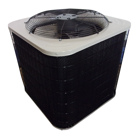
AIRE-FLO 14 SEER
AIR CONDITIONER UNITS
See
NOTES
CONTROL
BOX
GENERAL
This outdoor air conditioner with all-aluminum coil is
designed for use with HFC-410A refrigerant only. This unit
must be installed with an approved indoor air handler or
coil.
IMPORTANT: Special procedures are required for
cleaning the aluminum coil in this unit. See page 16 in this
instruction for information.
These instructions are intended as a general guide and do
not supersede local codes in any way. Consult authorities
having jurisdiction before installation.
NOTES -
Service clearance of 30 in. (762 mm) must be maintained on one of
the sides adjacent to the control box.
Clearance to one of the other three sides must be 36 in. (914 mm).
Clearance to one of the remaining two sides may be 12 in. (305
mm) and the final side may be 6 in. (152 mm).
A clearance of 24 in. must be maintained between two units.
48 in. (1219 mm) clearance required on top of unit.
FIGURE 1
As with any mechanical equipment, contact with sharp
sheet metal edges can result in personal injury. Take care
while handling this equipment and use protective cloth
ing.
Page 1
CAUTION
Advertisement
Table of Contents

Related Manuals for Aire-Flo 30


Summary of Contents for Aire-Flo 30
-
Page 1: Installation Instructions
STEP 1 -- SETTING THE UNIT -- Clearances See NOTES NOTES - Service clearance of 30 in. (762 mm) must be maintained on one of the sides adjacent to the control box. Clearance to one of the other three sides must be 36 in. (914 mm). -
Page 2: Slab Mounting
WARNING SLAB MOUNTING Install unit level or, if on a slope, maintain slope tolerance of 2 To prevent personal injury, as well as damage to panels, degrees (or 2 inches per 5 feet [50 mm per 1.5 m]) away from unit or structure, observe the following: building structure. - Page 3 WARNING WARNING When using a high pressure gas such as Refrigerant can be harmful if it is inhaled. Refrigerant nitrogen to pressurize a refrigeration or air must be used and recovered responsibly. conditioning system, use a regulator that Failure to follow this warning may result in personal injury can control the pressure down to 1 or 2 psig or death.
-
Page 4: Installation
LINE SET IMPORTANT — Refrigerant lines must not contact structure. INSTALLATION REFRIGERANT LINE SET — INSTALLING Line Set Isolation - The following illustrations are VERTICAL RUNS (NEW CONSTRUCTION SHOWN) examples of proper refrigerant line set isolation: NOTE - Insulate liquid line when it is routed through areas where the surrounding ambient temperature could become higher than the REFRIGERANT LINE SET —... - Page 5 STEP 2 -- REFRIGERANT PIPING -- Removing Existing Indoor Metering Device TYPICAL EXISTING FIXED ORIFICE TYPICAL EXISTING EXPANSION VALVE REMOVAL REMOVAL PROCEDURE PROCEDURE (UNCASED COIL SHOWN) (UNCASED COIL SHOWN) STUB END TWO-PIECE PATCH PLATE LIQUID LINE DISTRIBUTOR TUBES (UNCASED COIL ONLY) ORIFICE EXPANSION LIQUID LINE ORIFICE HOUSING...
-
Page 6: Cap And Core Removal
STEP 2 -- REFRIGERANT PIPING -- Brazing Procedures CAP AND CORE REMOVAL CUT AND DEBUR Cut ends of the refrigerant lines square (free from nicks or dents) Remove service cap and core from and debur the ends. The pipe must remain round. Do not crimp end both the suction and liquid line service of the line. -
Page 7: Braze Line Set
WRAP SERVICE VALVES To help protect service valve seals during brazing, wrap water-saturated cloths around service valve bodies and copper tube stubs. Use additional water-saturated cloths underneath the valve body to protect the base paint. FLOW NITROGEN Flow regulated nitrogen (at 1 to 2 psig) through the refrigeration gauge set into the valve stem port connection on the liquid service valve and out of the suction valve stem port. - Page 8 STEP 2 -- REFRIGERANT PIPING -- Installing Indoor Expansion Valve This outdoor unit is designed for use in systems that use either an fixed orifice (RFC) (included with outdoor unit), or expansion valve metering device (purchased separately) at the indoor coil. The expansion valve unit can be installed internal or external to the indoor coil.
-
Page 9: Step 3 -- Leak Test And Evacuation
STEP 3 -- LEAK TEST AND EVACUATION LEAK TEST HIGH MANIFOLD GAUGE SET TO SUCTION SERVICE VALVE (ANGLE OR BALL TYPE) NITROGEN OUTDOOR UNIT HFC-410A CONNECT GAUGE SET A - Connect the high pressure hose of an HFC-410A manifold gauge set to the suction valve service port. -
Page 10: Evacuate The System
STEP 3 -- LEAK TEST AND EVACUATION (CONTINUED) EVACUATION HIGH CONNECT GAUGE SET NOTE - Remove cores from service valves (if not already done). A - Connect low side of manifold gauge set with 1/4 SAE in-line tee to suction line service valve B - Connect high side of manifold gauge set to MANIFOLD... -
Page 11: Install Thermostat
STEP 4 -- ELECTRICAL -- Circuit Sizing and Wire Routing In the U.S.A., wiring must conform with current local codes WARNING and the current National Electric Code (NEC). In Canada, wiring must conform with current local codes and the current Fire Hazard. -
Page 12: Field Control Wiring
WIRE RUN LENGTH AWG# INSULATION TYPE connection using field-provided wire nuts: LESS THAN 100' (30 METERS) TEMPERATURE RATING ● Yellow to Y1 MORE THAN 100' (30 METERS) 16 35ºC MINIMUM. ● Black to C (common) FIGURE 12 Page 12... -
Page 13: Step 5 -- Unit Start-Up
FIGURE 13. Typical Unit Wiring Diagram 3 - After evacuation is complete, open the liquid line and STEP 5 -- UNIT START-UP suction line service valve stems to release the refrigerant charge (contained in outdoor unit) into the IMPORTANT system. 4 - Replace the stem caps and tighten to the value listed If unit is equipped with a crankcase heater, it should be in table 2. -
Page 14: Operating Angle-Type Service Valve
0 - 800 psig on the high side and a low NOTE - A label with specific torque requirements may be affixed to the side of 30” vacuum to 250 psig with dampened speed to stem cap. If the label is present, use the specified torque. -
Page 15: To Access Service Port
grille in the wall or ceiling. Check the filter monthly and TO ACCESS SERVICE PORT: clean or replace it as needed. A service port cap protects the service port core from contamination Disposable filters should be replaced with a filter of the and serves as the primary leak seal. - Page 16 Outdoor Unit 2 - Inspect and clean or replace air filters in indoor unit. 1 - Inspect component wiring for loose, worn or damaged 3 - Check the cleanliness of indoor blower and clean connections. Also check for any rubbing or pinching of blower, if necessary.
-
Page 17: Start Up Checks
Start-Up and Performance Checklist Customer Address Indoor Unit Model Serial Outdoor Unit Model Serial Notes: START UP CHECKS Refrigerant Type: Rated Load Amps: Actual Amps Rated Volts Actual Volts Condenser Fan Full Load Amps Actual Amps: COOLING MODE Suction Pressure: Liquid Pressure: Supply Air Temperature: Ambient Temperature:...
Need help?
Do you have a question about the 30 and is the answer not in the manual?
Questions and answers