Table of Contents
Advertisement
Quick Links
Download this manual
See also:
Installation Manual
Advertisement
Table of Contents

Related Manuals for ETC Ion


Summary of Contents for ETC Ion
- Page 1 Operations Manual Version 2.7.0 Part Number: 4310M1210-2.7.0 Rev A Released: 2018-05...
- Page 2 ETC®, Eos®, Eos Ti®, Gio®, Gio @ 5®, Ion Xe™, Ion®, Element 2™, Element™, ETCnomad®, and ETCnomad Puck® are either registered trademarks or trademarks of in the United States and other countries. All other trademarks, both marked and not marked, are the property of their respective owners.
-
Page 3: Table Of Contents
Table of Contents Introduction Using this Manual Register Your Console Online Eos Family User Forums Help from ETC Technical Services Other Reference Materials Important Concepts Console Overview Ion Geography Console Components Cleaning Your Console Console Capacities System Basics About System Basics... - Page 4 Setup About Setup System User Device Basic Manual Control About Basic Manual Control Selecting Channels Setting Intensity Manual Control of Non-intensity Parameters (NPs) Home Multiple Intensity Channels Multicell Fixtures Lamp Controls Using [+%] and [-%] Remainder Dim Highlight and Lowlight Sneak Select Keys Channel Check...
- Page 5 Deleting Palettes Storing and Using Presets About Presets Preset Options Storing Presets Live Recalling Presets Effects In Presets Editing Presets Live Using the Preset List Editing Presets in Blind Using By Type Presets Removing Channels From a Preset Deleting Presets Presets and Palettes Fader Properties Working with a Single Cue List About Single Cue List...
- Page 6 About Cue Playback Playback Controls Selected Cue Out-of-Sequence Cues Virtual Faders Assigning Faders Changing Fader Pages Playback Fader Controls Multipart Cues About Multipart Cues Record a Multipart Cue in Live Storing a Multipart Cue in Blind Deleting a Part from a Multipart Cue Creating and Using Effects About Effects The Effect List...
- Page 7 Execute List Freeze and StopEffect on Submasters Moving and Copying Submasters Releasing Content From a Submaster Updating a Submaster Deleting a Submaster Using About About [About] [About] {What's New} [About] System [About] Channel [About] Address [About] Cuelist [About] Cue [About] Curves [About] Effects [About] Groups [About] Submaster...
- Page 8 Creating and Editing Magic Sheets Examples of Magic Sheets Virtual Media Server About Virtual Media Server Media Content Exporting Media Content Patching the Virtual Media Server and Layers Creating a Pixel Map Working with the Virtual Media Server Effect Layers Pixel Mapping in a Multi-Console System Using Partitioned Control About Partitioned Control...
- Page 9 Facepanel Shortcuts Overview Displays Facepanel Operations Eos Family Hotkeys...
-
Page 11: Introduction
Introduction This chapter contains the following topics: Using this Manual Register Your Console Online Eos Family User Forums Help from ETC Technical Services Other Reference Materials Important Concepts Introduction... -
Page 12: Using This Manual
Registering your console with ETC ensures that you will be notified of software and library updates, as well as any product advisories. To register your console, you will need to enroll in “My ETC,” a personalized ETC website that provides a more direct path of communication between you and ETC. -
Page 13: Help From Etc Technical Services
If you are having difficulties, your most convenient resources are the references given in this user manual. To search more widely, try the ETC website at etcconnect.com. If none of these resources is sufficient, contact ETC Technical Services directly at one of the offices identified below. Emergency service is available from all ETC offices outside of normal business hours. -
Page 14: Important Concepts
Live and Blind HTP vs. LTP Channel A channel is a single numerical name that is used by Ion to control a dimmer, a group of dimmers, a dimmer and a device, or a complete moving light fixture. Ion Operations Manual... - Page 15 Other actions bypass the command line entirely. Enter Since the command line can receive multiple edits and instructions at once, it is necessary to let Ion know when you have completed your instruction in the command line. This is done with the [Enter]...
- Page 16 Tracking vs. Cue Only Ion is, by default, a tracking console. This means two things. First, tracking relates to how cue lists are created. Once data is in a cue list, it will remain a part of that cue list, at its original setting, until a new instruction is provided or until it is removed from the cue list using filters or null commands.
- Page 17 Ion also has a [Cue Only/Track] button that allows you to record or update a cue as an exception to the default setting. Therefore, if the console is set to Tracking, the button acts as Cue Only. If con- sole is set to Cue Only, it behaves as a Track button.
- Page 18 Cue List Ownership Ion is capable of running multiple cue lists. Cue list ownership is determined by the cue from which a channel is currently receiving its value. In Live, a parameter is considered to be “owned” by a cue list when it is receiving its current value from that cue list.
- Page 19 In LTP, the most recent level received will be executed. Cue lists can oper- ate as HTP or LTP for intensity parameters only. Non-intensity parameters (NPs) are always LTP. Sub- masters can operate as HTP or LTP for intensity. The default is HTP. Ion’s default cue list setting for intensity is LTP.
- Page 20 Any new values sent to the channel will supersede any previous values, regardless of the level supplied. Ion determines the LTP value for a channel, which is overridden by any HTP input values that are higher than the LTP instruction. This is then finally modified by manual control.
-
Page 21: Console Overview
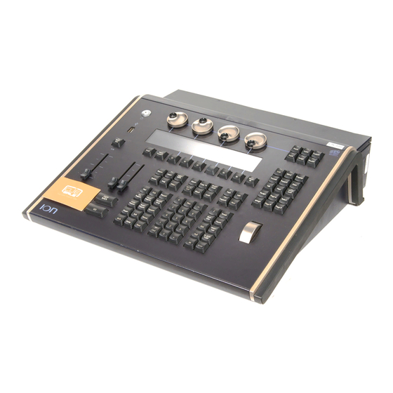
C h a p t e r 1 Console Overview Inside this section you will find general descriptions of your console and various areas of the user interface. This chapter contains the following topics: Ion Geography Console Components Cleaning Your Console Console Capacities Console Overview... - Page 22 Ion Geography Below is a diagram of Ion with references made to specific areas of use. The terms and names for each area and interface are used throughout this manual. Note: Ion can support up to 2 monitors. For more information, see...
- Page 23 CAUTION: The USB ports cannot be used for charging devices such as cell phones. External Monitors Ion can support up to 2 monitors, either 2 DVI monitors or 1 display port and 1 DVI. Console Overview...
- Page 24 If blackout is currently on, a blackout button will be shown at the top of the displays. Clicking on either button will open a new display which will allow you to turn off blackout and set the grandmaster to a different level. Ion Operations Manual...
- Page 25 Load buttons are used to load the specified cue or submaster to the associated fader. Ion has a load button located above the master playback controls to assign content to it. Fader wings use a combination of both bump buttons beneath the faders as load buttons.
- Page 26 ETCNet2 directly, no gateway or node is required. Ion has two DMX ports. To output, connect one 5 pin XLR cable per port. The first port will default to outputting the first universe of DMX, addresses 1-512, and the second port to the second universe, outputting addresses 513-1024.
- Page 27 Console Capacities Output Parameters 1k (Min) 6k (Max) Channel Counts 32,768 channels (can be any number from 1 to 99,999) Cues and Cue Lists Up to 999 cue lists Up to 10,000 cues Record Targets 1,000 Groups 1,000 x 4 Palettes (Intensity, Focus, Color and Beam) 1,000 Presets 1,000 Effects 99,999 Macros...
- Page 28 Ion Operations Manual...
-
Page 29: System Basics
C h a p t e r 2 System Basics This chapter contains the following topics: About System Basics The Central Information Area (CIA) Browser Softkeys Displays Display Control and Navigation Live and Blind Displays Playback Status Display Using Direct Selects Encoders Moving Light Controls Fader Configuration... -
Page 30: About System Basics
This will provide power to all internal electronics. 3. Press the power button, located on the face panel. The button LED will illuminate blue to indic- ate the console is running. The console will boot up into the Ion environment. The system is now ready for use. - Page 31 Favorite CIA Display You can select a favorite default display for the CIA that will show when [Displays] is pressed. The standard default display for the CIA is the Browser. The favorite display will show a gold star icon at the top of the CIA by the arrow and lock icons. Dis- plays that can be selected as a favorite, but are currently not, will show a gray star at the top of the CIA.
- Page 32 When collapsed, only the {All NPs}, {All Speed}, and {Expand Arrow} buttons will be displayed. Labeling [Label] is used to attach an alphanumeric label to an object such as cues, channels, submasters, etc. [Label] [Label] when appended to a record target command, clears the current label. This includes show file labels.
-
Page 33: Browser
[Page p] - takes the cursor to the beginning of the label. [Pageq] - takes the cursor to the end of the label. [Paget] - moves the cursor to the left. [Pageu] - moves the cursor to the right. Browser The browser is the interface for numerous functions including saving a show, loading a show, open- ing displays, and many other functions. - Page 34 From this menu you can select one of the available clear options by clicking on the desired button in the CIA. Ion will ask you for a confirmation before performing the selected clear. For {Clear Targets}, Ion will allow you to choose which record targets you want to clear.
-
Page 35: Softkeys
This will also lock any wings or USB connected peripherals. Softkeys Some of the features and displays in Ion are accessible from the softkeys, which are located under the Browser. Softkeys are indicated in documentation with bold {braces}. The softkeys are context sensitive, therefore they repaint to display softkeys relevant to the display or command you are working with. -
Page 36: Displays
Ion has the ability to have one of three different workspaces active on individual monitors, as well as to have up to four frames in use in any workspace. Each frame can hold multiple tabs. Each tab con- tains one display. - Page 37 Workspaces 1, 2, and 3 These three monitor icons are used to switch between each monitor’s available workspaces. Each can be set up to include any of the desired layout, displays, and controls options offered on the Home Screen or the Display Controls Screen.
- Page 38 30 Command History Display Tabs The following displays can be selected, and they will open in a new tab in the selected frame: The following displays can have multiple instances open: Channel (Summary) Channel (Table) Split Channel Ion Operations Manual...
- Page 39 Playback Status Display Magic Sheet Display Effect Channels Park For multiple instances of the same display, the tab number will be followed with a decimal number. Additional tabs will start their numbering with n.2. If you have only one instance, there will be no decimal number.
-
Page 40: Display Control And Navigation
You can open list views of any record target by double-pressing the key for the desired record target (for example, [Cue] [Cue] opens the cue list index). From the Softkeys To open any displays accessible from the softkeys, press [Displays]. The softkeys will repaint to dis- play: Effect Status Color Picker Ion Operations Manual... - Page 41 Patch Setup Browser Magic Sheet Workspace Command History Curves Pixel Maps Show Control Mirror Any of these softkeys will open the associated display with a single press. Closing Displays To close any tab display, select the display by using the [Tab] key or other means of navigation. When the desired display is active, press [Escape] to close it.
- Page 42 Display Controls Screen Selecting the display controls icon will grant you access to the Layout Options (on the previous page). Choose the layout icon for the arrangement and number of frames you want to use on the monitor. Ion Operations Manual...
- Page 43 This screen also offers options for opening and closing tabs as well as resizing and resetting the mon- itor(s). Resize Frames Select this icon to resize frames in any of the workspaces on the monitor. After selecting, resizing tools will appear between frames of the workspace and you can select and drag the resize tool icons to adjust sizing as needed.
- Page 44 [Page q] - scrolls table, spreadsheet and channel views down, [Page p] - scrolls table, spreadsheet and channel views up, [Page u] - scrolls table and spreadsheet views right, [Page t] - scrolls table and spreadsheet views left. Ion Operations Manual...
- Page 45 Selecting Displays When a display is selected, the screen is highlighted in a gold border and the display name (such as “1. Live Channel”) will be in gold as well. When a display is not selected, there is no border and the tab name is gray.
- Page 46 This option displays your favorite snapshots in a small popup window for quick access. Select a snap- shot to recall it. Favorite is an option that can be selected or deselected when recording a snapshot. Press the camera icon to close the display when opened. Ion Operations Manual...
-
Page 47: Live And Blind Displays
About Snapshots (on page 376) for more information. [Time] Key Pressing and holding [ [About] & [Time]] allows you to view discrete timing data behind any channel parameter. [Time] exposes channel or parameter specific timing for any channels in the current cue. The first value is the delay time. - Page 48 When the summary view has been collapsed to show only intensity data, you may include focus, color, or beam data in the summary view by holding down [Data] and any of the encoder paging keys (Focus, Color, Image, Shutter, or Form) This displays all categories again. Ion Operations Manual...
- Page 49 In Live, table view displays all active channel data being output from Ion. In Blind, it will display all data for a single record target (cue, preset, palette) depending on what is viewed. In table view, focus, color, and beam information can be viewed in either a summary of these three categories or an expanded view to show all parameter data.
- Page 50 {Preview}<Cue>[5] will preview cue 5. Channels in Use To open the Channels in Use display, click on the {CIU} icon in the home screen or press [Tab] &[3][2]. A Channels in Use display shows the following information for each channel: Ion Operations Manual...
- Page 51 Live and Blind Configuration Menu (on page 54) Indicators in the Live/ Blind Display Ion relies on many traditional ETC indicators which you may be familiar with, as well as some new ones. This section identifies the graphical and colorful conventions used in Ion to indicate conditions to you.
- Page 52 Most of the channels in the above image are conventional channels (intensity is the only available parameter). Several channels in the image are moving lights (possessing more parameters than just intensity). Conventionals Conventions display only the top field, intensity, as no other parameters are available on a con- ventional channel. Ion Operations Manual...
- Page 53 Moving Lights or Multi-parameter Devices This view also has additional data fields beneath intensity (F, C, B). This information can be sup- pressed by pressing and holding [Data] and any of the encoder paging keys (Focus, Color, Image, Shutter, or Form). Doing so will leave only the intensity field and FCB indicators at the bottom of the channel.
- Page 54 A decimal will display at the end of a master channel when flexi cells off is on. Color Indicators Ion uses color to indicate the selection state and information about channel/parameter levels. Channel Numbers/ Channel Headers Gray number Unpatched channel number.
- Page 55 Dark Red Manual Data (any data that has been set but not yet stored to an active cue or sub- master) from other consoles that are using different user IDs. Blue The intensity value is higher than in the previous cue. Non-intensity parameters (NPs) are in blue when any move instruction has occurred.
- Page 56 Each instance of Live/ Blind may be configured individually. The following options are available: Suppress Target Status Bar - Hides the target status bar from the display. The target status bar displays at the bottom of the Live/ Blind displays. Ion Operations Manual...
- Page 57 MC Line Wrap - When enabled, this option keeps all of the cells together of a multicell fixture when viewing it in Live summary view instead of breaking them up across multiple rows. Suppress Target Labels - Hides the Label column in Blind spreadsheet view. Show Reference Labels - When enabled, referenced record targets (such as presets or palettes) with labels will have their labels displayed rather than their target type and number.
- Page 58 You may also engage a “Channels with Timing” flexichannel state by pressing [Flexi] & [Time]. This will display all channels that have discrete timing in the current cue and will remove channels without discrete timing from view. Ion Operations Manual...
-
Page 59: Playback Status Display
The display will remain in this state until you disengage it by pressing [Flexi] again. About & Display Toggles While in Live/Blind, you can use the [About] key to view additional information. When in an [About] mode, the mode type will display in the upper left hand corner of the Live/ Blind display. - Page 60 Pressing [Format] with the playback status display active will access this format. In expanded cue list, the view of the active cue list increases to the full size of the display. The current fader page is visible at the bottom of the screen. Ion Operations Manual...
- Page 61 Fader Display Format Pressing [Format] with the playback status display active will access this format, which shows a view of the fader configurations for 10 pages of 10 faders each (for a total of 100 visible faders. Each fader is color coded based on its assigned target type. Grandmasters and inhibitive submasters are in red, additive submasters are yellow ,playback faders display in green ,and presets and palettes are orange.
- Page 62 Playback Status Display Configuration (on page 63) for more information). Note: The first time you access the split playback status display, you may need to adjust the splitter bar between the two lists to see the second list. Ion Operations Manual...
- Page 63 PSD visible showing that cue list, nothing will be paged. Indicators in the Playback Status Display Ion relies on many traditional ETC indicators which you may be familiar with, as well as some new ones. This section identifies the graphical and colorful conventions used in Ion to indicate conditions to you.
- Page 64 Found in the cue display “Flags” area. B or b (see cues 2 & 5) - Indicates a blocked cue. “B” indicates the entire cue is blocked. “b” indicates a channel/ parameter block only. Found in the cue display “Flags” area. Ion Operations Manual...
- Page 65 F1 - F10 - Indicate faders numbered 1 through 10 on the console. Found at the bottom of the fader display. F5 (see in cue 1) - Indicates a follow time associated with the cue (in this case, 9 seconds). Found in the cue display.
- Page 66 Break Link to Live/Blind - When selecting the Live/Blind display, the PSD will also come into view if it is currently hidden. This option allows you to break the link between the PSD and the Live/Blind displays so that the PSD will no longer come into view when selecting Live/Blind. Ion Operations Manual...
-
Page 67: Using Direct Selects
Reorder Columns Reorder columns allows you choose what data displays in the PSD and what order it displays in. By default, all columns except notes will be displayed. The arrow keys on the right can be used to move columns around. Columns are moved in groups. To select a column header to move, click or tap the name. - Page 68 You have considerable flexibility in how you organize the direct selects by using the options in the configuration menu. To access the configuration menu, right click or tap on the direct select's tab to see the con- figuration menu. Ion Operations Manual...
- Page 69 The following options are available: # of Banks - sets the number of direct select banks that will display. Layout 25, 50, 100, 200 - allows you to select the number of buttons that will display per bank. Rows - allows you to select the number of rows in the banks. Columns - allows you to select the number of columns in the banks.
- Page 70 [1] [Thru] [5] [Enter]. Then double click on a direct select to assign the selection. Note: To assign a range of channels to the direct selects, you will need to use the con- figuration window. From the command line, you can only assign one channel at a time. Ion Operations Manual...
- Page 71 Scenes on Custom Direct Selects Scenes can be assigned to custom direct selects. To assign a scene to a direct select, you can either tap on a direct select to open the configuration window, or you can use the command line. From the configuration window, you can select the target type of scene, and the scene number.
- Page 72 Direct selects can be placed into a flexi mode, which will remove empty tiles. {Use Flexi} needs to be enabled in the Direct Selects configuration menu. See Direct Selects Configuration Menu (on page 66). When enabled, the {Flexi} button will display in the direct selects display. Ion Operations Manual...
-
Page 73: Encoders
(on page 160) Encoder Controls Display On Ion, the encoder LCD displays the active parameter category loaded on the encoders, as selected by the page buttons. To see additional encoder information, open the Encoder Display by using CTRL + ALT + \on an alphanumeric keyboard. ALT + , can be used to change encoder pages. - Page 74 Press {Expand} to see all of the information about any device with a frame table. Press again to col- lapse to the normal view. You may make selections from the Expand screen. The colors/images in the device are established in patch (see Using the Scroller/Wheel Picker and Editor (on page 111)). Ion Operations Manual...
-
Page 75: Moving Light Controls
Encoder Navigation Use the encoder page buttons (located to the upper right of the encoder LCD) to choose which para- meters are currently available on the encoders. There are six readily usable buttons: [Focus], [Color], [Custom], [Form], [Image], and [Shutter]. Pressing any of these will change the parameters controlled by the encoders. -
Page 76: Fader Configuration
Master Fader Configuration (on page 78) for more information. The fader configuration display shows a virtual mockup of each fader and its buttons. The various parts of the virtual fader can be clicked or tapped to open configuration options. Ion Operations Manual... - Page 77 Each fader is color coded based on its assigned target type. Grandmasters and inhibitive submasters are in red, additive submasters are yellow ,playback faders display in green ,and presets, palettes, global effects, and manual time masters are brown. Fader Configuration Window Click on the fader header to open the fader configuration window.
- Page 78 Presets and Palettes Fader Properties (on page 228) Global Effects Fader (on page 333) Manual Time Master (on page 79) Fader List The Fader List, which shows all of the faders and their assignments, can be found in Tab 35. Ion Operations Manual...
- Page 79 You can also make changes to a fader's configuration while in the fader list display by clicking on a column. A virtual fader will be displayed. Click on the appropriate area of the fader to access the con- figuration options. Selection can be done by clicking in the column or from the command line. Range editing is possible in this display by selecting all the needed faders.
- Page 80 If a device changes its user ID, the cue list on the mas- ter will be remapped accordingly. Additional configuration options are available. Please see Cue List Properties (on page 263) for more information. Ion Operations Manual...
- Page 81 Grandmaster Configuration When a fader is configured as a grandmaster, you can set the fader itself as a master or disable it. Fader size is set to 1x, and can not be changed. The first button is locked as a load button, and cannot be configured. The second button is disabled and cannot be configured.
- Page 82 (Tab 36) or in the fader list (Tab 35). For cue lists and submasters, channel and parameter filters can be set in the following areas: Cue List Index Submaster List Fader configuration display (Tab 36) Ion Operations Manual...
- Page 83 Fader list (Tab 35) In Live using the {Properties} softkey Tap or click on {Chan Filter} to assign channels or groups. Tap or click on {Param Filter} to open a list of available parameters that you can filter. Note: Filters will travel with their assigned cue lists and submasters wherever they are mapped.
-
Page 84: Virtual Keyboard
1 and places it in fader 4. Levels, effects, and labels are not copied when using the {Attrs Only} softkey. Virtual Keyboard It is possible to open a keyboard which mimics the hard keys found on the actual Ion keypad. To open, you can select the virtual keyboard from the Home Screen (on page 39) or use [Tab] [7]. -
Page 85: Sacn Output Viewer
C - CTRL A - ALT sACN Output Viewer You can open the sACN Output Viewer by pressing [Tab] & [3][7] or selecting the sACN Output Viewer icon from the home screen. The sACN Output Viewer is a place to check the current live outputs on a universe by universe basis. The left side of the viewer is the universe grid. - Page 86 The following options are available in this configuration menu: {Follow Command Line} - when enabled, the viewer will follow the command line for selecting addresses. This is enabled by default. Universe - you can select which universe to jump the viewer to. Ion Operations Manual...
-
Page 87: Managing Show Files
C h a p t e r 3 Managing Show Files This chapter contains the following topics: About Managing Show Files Create a New Show File Open an Existing Show File Merging Show Files Printing a Show File Saving the Current Show File Importing Show Files Exporting a Show File Exporting Logs... -
Page 88: About Managing Show Files
Press {OK} to confirm or {Cancel} to discontinue the operation. On Ion, you can select to have a 1-to-1 patch by pressing the {Patch 1to1}. A new show created with {Patch 1to1} selected will have a 1 to 1 patch and 1 to 1 channel to sub assignment. - Page 89 To stop the show load process, press the {Cancel} button. When you have selected/deselected all of the show components you require, press the {OK} button. Ion loads the selected show to the console. CAUTION: On a partial show open, if any record targets are not opened, any existing data of that type will be cleared from the console.To merge show data, merge should be used.
- Page 90 It is important to remember that on a partial patch open, if any record targets are not opened, any existing data of that type will be cleared from the console. To keep that data, merge should be used. Ion Operations Manual...
-
Page 91: Merging Show Files
USB device. To merge a show file, navigate within the Browser to: File> Merge>. Navigate to the desired storage location and press [Select]. When using merge, Ion displays only the available files. Navigate to the specific file and press [Select]. - Page 92 CIA. The components will appear in the list to the right as you select them. 4. Press any fields for which you want to enter specific numbers. The field (if editable) will high- light in gold. Ion Operations Manual...
-
Page 93: Printing A Show File
Printing a Show File Ion provides you with the ability to save a show file or aspects from a show file to a PDF file for print- ing. Ion has three locations to save the PDF files including the Show File Archive, the File Server (if connected), or a USB device (if connected). - Page 94 You can also choose to print specific portions of show aspects. To select this information, press the {Advanced} button. The buttons at the center of the CIA will again represent all of the show aspects that you can choose. By default all aspects will be deselected (black). Ion Operations Manual...
-
Page 95: Saving The Current Show File
As you select aspects, they will be added to the table in the CIA. For each component in the list, you can specify the desired range by pressing the proper area in the table and entering numbers from the keypad. The columns in the table are: List - The list you are taking data from (such as a cue list). -
Page 96: Importing Show Files
If you are importing an USITT ASCII file, you will have two options, Import as Library Fixtures or Import As Custom Fixtures. Import as Library Fixtures will allow Ion to try to match the fixtures in the file with fixtures in the Ion library. - Page 97 You can select starting and ending channels for the import. Mapping You can map Ion patch fields to fields in the Lightwright file. Channel and Address must be mapped for the file import to work. Any other field can be set to ignore if desired. Once a Lightwright field has been mapped, it will display in grey in the dropdown menu.
-
Page 98: Exporting A Show File
Address Formats Ion will accept mulitple address formats for importing. Examples of those formats are 2/3, 2.3, 2,3, 2-3. Ion will convert all formats to n/n. Device Mapping Devices can also be mapped. Click {Map Devices} to open the following display. -
Page 99: Exporting Logs
An exporting logs message will appear while the log files are being created. Deleting a File Ion provides you with the ability to delete show files from the Show File Archive and the File Server from within the Browser. To Delete a Show File Navigate within the Browser to: File>... -
Page 100: File Manager
File Manager Ion has a File Manager (on page 463), which also provides a way to manage show files. Ion Operations Manual... -
Page 101: Patch
C h a p t e r 4 Patch This chapter contains the following topics: About Patch Patch Main Displays Patching Conventional Fixtures Patching Moving Lights, LEDs, and Accessories Patching MultiCell Fixtures Labeling Using the Scroller/Wheel Picker and Editor Settings in Patch Using Device List Clearing the Patch Update Library... -
Page 102: About Patch
About Patch Ion treats fixtures and channels as one and the same, meaning each fixture is assigned a single con- trol channel number. Individual parameters of that fixture, such as intensity, focus, color, and beam are also associated with that same channel number but as additional lines of channel information. - Page 103 The patch screen will display the following information if available: Channel - the patched channel number. In patch by address mode, channel will appear blank if not currently patched. Address - the patched output address. In patch by channel mode, address will appear blank if not currently patched.
-
Page 104: Patching Conventional Fixtures
Patching By Channel (below) Patch- ing By Address (on the facing page). Ion defaults to patch by channel mode. Pressing [Format] while in the patch display will toggle the mode between patch by channel and patch by address. Note: When working with conventional devices, you can patch in either mode easily. - Page 105 [2][0][3] [At] [1][2] [Enter] - patches address 203 to channel 12. Note: If, at any point, you try to patch an address that is already in use, Ion will post an advisory to indicate this, preventing you from duplicating addresses in your patch.
- Page 106 Replace By default, if you patch an address to a channel that is already patched, Ion will create a new part for the new address. If you want to replace the current address with the new, use {Replace}: [n] {Replace} [n] [Enter] - replaces the address in part 1 of the selected channel.
- Page 107 By default, doubled dimmers start with an offset network DMX address value of 20000. Therefore, in the above example, address 1B (channel 97) is actually controlled by network DMX address 20001. Address 2B is actually controlled by network DMX address 20002 and so on. This offset matches the default offset in CEM+ / CEM3 when configuring your Sensor dimmer rack for dimmer doubling.
- Page 108 Using the {Offset} feature in patch allows you to force a numerical offset between the starting address of channels in patch or for offsetting your channel selection. This feature is useful when you have configurable devices in your show, such as a Source Four Revolution, which has option slots for Ion Operations Manual...
- Page 109 By default, Ion will add a part if you are trying to patch to a channel that has already been assigned an address.
-
Page 110: Patching Moving Lights, Leds, And Accessories
Press {Search} to open the search window. You will need an external alphanumeric keyboard or you can click the keyboard icon in the search window to open the virtual keyboard. You can also nav- igate the list as you would the browser. You can search by manufacturer name, fixture name, part of Ion Operations Manual... -
Page 111: Patching Multicell Fixtures
a name, and by DMX footprint. For example, if you searched for 31, you would see all of the fixtures that have a DMX footprint of 31. Double clicking on a fixture name will patch it. In the search window, press {Parameters} to view a parameter list for a fixture, or press {Fixture Notes} to see any notes that exist for it. -
Page 112: Labeling
To label a channel or address, press the [Label] key with the channel or address selected on the com- mand line. You can use the virtual alphanumeric keyboard or an external keyboard to enter the desired label text. Ion Operations Manual... -
Page 113: Using The Scroller/Wheel Picker And Editor
In the above image, {ETC Scroll} is the default scroll for the selected ETC Source Four Revolution. The list of gel colors as they are installed in the scroll are displayed to the left with a color chip for easy ref- erence. - Page 114 To select a color or pattern for the specific frame in the scroll/wheel, select the “NEW” text and press {Edit} or click the gray box in the C/G column of the frame. The available gel, color, gobo and effect media selections will be displayed. Ion Operations Manual...
- Page 115 The media selection includes the following softkeys: {Gel}, {Color}, {Gobo}, and {Effect} - each will display available media selections as they are cata- loged by the associated scroll or wheel manufacturers. {Open Frame} - places the frame in Open White. Generallly, the first media frame is open. {Cancel} - cancels the media selection and returns to the frame editor.
- Page 116 Scroller Using the ML Display (on the facing page). Note: It is recommended that you calibrate your scroller frames starting with the last frame and working backward to the first frame. This will help ensure a complete and accurate cal- ibration. Ion Operations Manual...
- Page 117 Note: Calibration may need to be performed when you initially patch a scroller and may need to be adjusted through the course of operation as spring tension changes in a color scroller. To calibrate a scroller: 1. Select the channel of the scroller you wish to calibrate. 2.
- Page 118 Scroller wheels and their calibration data can be copied to other channels. [1] {Copy Scroller} [2] [Enter] - copies the scroller and calibration data from channel 1 to chan- nel 2. Scrollers that have calibrated data will display a “~” after their name. Ion Operations Manual...
-
Page 119: Settings In Patch
When creating and editing your patch, page through each of these softkeys individually to enter more specific data about your selected device. {Patch} Display and Settings With patch open, Ion defaults to this display. It provides access to data input fields that you may use to define devices in your lighting system. Note: The Artnet and sACN offset will display here. - Page 120 Ion will draw this information from the library data. If you wish to leave a larger output gap than required by the library, use [Offset]. See Using {Offset} in Patch (on page 106).
- Page 121 {Flash} - will bring a channel or address to full, and then every other second the level will move to 15%. That will hold for 1 second, and then the level will return to full. The channel or address will keep flashing until either the command line is cleared or {Flash} is selected again. {Attribute} Display and Settings The {Attributes} page provides you with optional fields for additional information and details about the configuration of your rig.
- Page 122 [5] {Attributes} {Effect Wheels} - selects channel 5 and opens the wheel picker in the CIA for effect wheel selection. Ion Operations Manual...
- Page 123 {Database} Display and Settings The {Database} page provides you with additional fields for entering information that can be used by the Query function. See Using {Query} (on page 286). These fields include {Notes} and {Text 1} through {Text 10}. Clicking on {Text 1} through {Text 10} will open up a display for selection of keywords.
-
Page 124: Using Device List
Note: Consoles only support RDM devices that are connected through a Gadget, Local I/O, or external ACN gateway. Supported gateways are the ETC Net3 4 or 2 port Gateways. Gateways need to be running version 5.1 or newer. Ion Operations Manual... - Page 125 Open the Dimmer Feedback display while in the Patch display by pressing {Device List}> {Dimmers}. When the dimmer list is opened, the dimmers will be displayed in Patch by Address mode. Ion will display the following information that it receives from the dimmers: Address...
- Page 126 Interface Protocols (on page 458) If using Network RDM, this must be done via an ETC Net3 Gateway and RDM must also be enabled on the DMX ports of the Gateway. The Gateway needs to be running version 5.1 or newer.
- Page 127 Model Footprint Ion will also display what personality from the library the device matches in the Eos Type column. This information will not display until you first select the device. Once the device has been selected for the first time, Ion will extract the type information from the device and display it.
- Page 128 Patching Discovered Dimmers and RDM Devices When dimmers/devices are discovered, they are not automatically attached to any patched channels in Ion. If you want the benefits of dimmer or RDM feedback, you must attach a dimmer or device to a channel.
- Page 129 The desk warns you when a channel’s attached dimmer has an error or is offline. Items that are attached between patch and the device list will display a caret (>) beside their channel/address in patch. The advantages of attaching a device to a channel are: Its fixture type is copied to the channel.
-
Page 130: Clearing The Patch
{Cancel} from the confirmation screen. Update Library When a new library is installed on Ion either from a software update or a separate fixture library file from the ETC website, changes in library data will not automatically update your show files. This is to prevent library changes from affecting a functional show file. -
Page 131: Fixture Editor
Fixture Editor Ion provides you with the ability to create your own fixture type within patch and store it with your show file. You can name the fixture, assign all necessary parameters, define the address and oper- ational range of those parameters, and set lamp controls. - Page 132 6. Click on the slot to open a dropdown list of available parameters. Click on a category to open the dropdown list to see the parameters. 7. Press the desired parameter to assign it. Ion Operations Manual...
- Page 133 8. Repeat steps 5 through 7 until you have entered all of the required parameters for the new fix- ture. If you are missing a parameter slot: At any point you can use the [Page] keys and {Insert}, to insert a parameter slot above the selected one.
- Page 134 For many devices, their lamp and motor control functions can be controlled remotely using DMX. These will often require use of a timed sequence of DMX levels to control various functions such as striking the lamp, resetting the fixture, and other specific actions. To define the lamp controls for a device: Ion Operations Manual...
- Page 135 You may setup as many levels as needed for each step. Snap Parameters Certain parameters may not want to be subjected to cue timing. Those parameters can be set to snap. By default, Ion will snap the parameters listed in the following table: Beam FX Effect Library...
- Page 136 For more information, see Partial Patch Merging (on page 91) Importing a Custom Fixture You can import custom fixtures from an ASCII show file, see Importing Show Files (on page 94) Ion Operations Manual...
-
Page 137: Setup
C h a p t e r 5 Setup This chapter contains the following topics: About Setup System User Device Setup... -
Page 138: About Setup
The CIA will repaint to display the setup screen and the softkeys will change to display the various subcategories of setup. Ion defaults to display show settings, however if you have changed the view to another subcategory, Ion will remember the view you were in when you return to setup. - Page 139 channels can exist in the patch, but they can be distributed throughout the entire 99,999 channel count. Enter the number of channels for your system using the keypad. This entry must be con- firmed with the [Enter] key. Note: Every part in a multipart channel will count as an additional channel for the channel count total.
- Page 140 {SMPTE Time Code Rx} This button is used to control whether your console can receive SMPTE time code. Choosing “Dis- abled” will disable all time code lists that have a SMPTE source. The default for this setting is “Enabled”. Ion Operations Manual...
- Page 141 {Resync Frames} This button allows you to configure how many frames need to be synced before time code starts run- ning. Frames can be from 1-30. Default is 2 frames. MIDI {MSC Receive} This button toggles the setting for receiving MIDI Show Control from an external source between “Enabled”...
- Page 142 The contact closure only reports on/off even though it is considered an analog input. Note: The contact closures require DC voltage, which is supplied by the console on pins 14+15. See the diagram below. Relay Out Allows you to assign the Relay Out Source ID and the Relay Out Address. Ion Operations Manual...
- Page 143 This setting specifies the UDP port that the console will listen to for OSC receiving strings. Note: ETC recommends using 8000 and 8001 respectively for port numbers. Remember that when setting port numbers on your external device that they should be set to the opposite of what Eos is set.
- Page 144 Allows the user to specify a list of specific comma separated names of devices to send strings tom for example, for use with Paradigm. {String TX Port} Setting for the UDP destination port that the console will send strings. Ion Operations Manual...
-
Page 145: User
{String TX IP Address} Sets the destination IP address or ACN devices supporting the ACN String EPI that the console will use to send strings. This can contain either an IP address for UDP string destinations or ACN device names.. A combination of UDP and ACN devices are not supported. Please see String Interface (on page 499) for more specific configuration information. - Page 146 If set to Latest, {Emergency Mark} will not set a mark flag. It will instead create a broken mark, which will display an x in the previous cue in the Playback Status Display. Manual Control This user setting button gives you access to manual control settings. Ion Operations Manual...
- Page 147 Manual Time In this section you may change the default times for manual changes to occur in live. Times can be set for each parameter category (Intensity Up, Intensity Down, Focus, Color, and Beam). You may use the [Thru] key to enter a value for all categories. {Int Up} [Thru] [9] [Enter] The default for each of these is 0 seconds.
-
Page 148: Device
Changes to this setting will require a restart. A warning message indicating a needed restart will display. This specifies the name the console will use to identify itself on the network to other devices. Examples might be Booth Desk and Tech Table. This setting is also available in the ECU. Ion Operations Manual... - Page 149 Outputs This System button gives you access to Outputs settings. These settings are also found in the ECU. Note: Changes to these settings may require a restart. When required, a warning message indicating a needed restart will display. Local DMX The following settings are available: Enable - enables DMX output from the local DMX ports.
- Page 150 This screen allows you to manually configure the positions of fader wings connected to your con- sole. The console will default to configuring the wings on its own. To manually configure, you must click on the {Manual Config. Off} softkey. Ion Operations Manual...
- Page 151 Clicking on the {Manual Config. Off} button turns manual configuration on and displays the Fader Wing Configuration screen. Clicking{Identify} will display numbers on each wing’s display to aid in configuration. The numbers do not identify the wings as to their actual order. Order is determined from left to right. The left most wing will contain the first faders.
- Page 152 This button resets all three trackball settings back to their default. Brightness Settings This screen on Ion allows you to adjust the brightness and contrast settings for the Ion display, sub- wing display, the light level for desk lamps, and the direct select brightness.
- Page 153 Ion Display The brightness and contrast levels of the LCD display on Ion can be adjusted. The level range is from 0-100%, with 50% being the default level. Subwing Display For attached wings, you can adjust the brightness and contrast of the wing's LCD displays. The level range is from 0 through 100%, with 55% being the default level.
- Page 154 Ion Operations Manual...
-
Page 155: Basic Manual Control
C h a p t e r 6 Basic Manual Control This chapter contains the following topics: About Basic Manual Control Selecting Channels Setting Intensity Manual Control of Non-intensity Parameters (NPs) Home Multiple Intensity Channels Multicell Fixtures Lamp Controls Using [+%] and [-%] Remainder Dim Highlight and Lowlight Sneak... -
Page 156: About Basic Manual Control
Channels are deselected when any action is taken on the keypad that is unrelated to manual control, such as recording groups and cues, or updating a record target, etc. You can also press [Clear] after a terminated command line to clear the channel selection. - Page 157 Modifying a Terminated Channel Selection It is possible to add or remove channels from a previously terminated command line. You will need to first press [+] or [-] and then you can add to or remove from your current channel selection. This includes selecting channels from the direct selects, summary view, and Magic Sheets.
- Page 158 [1] [Thru] [2] [4] {Offset} [4] [/] [4] [Enter] - selects channels 4, 8, 12, 16, 20, and 24. You can select to offset by 2/2, 4/4, 3/3 etc. [1] [Thru] [1][2]{Chan Per Group} [3] {Jump} [1] [Enter] would create these 3...
-
Page 159: Setting Intensity
Channels are deselected when any action is taken on the keypad that is unrelated to manual control, such as recording groups and cues, or updating a record target, etc. You can also press [Clear] after a terminated command line to clear the channel selection. -
Page 160: Manual Control Of Non-Intensity Parameters (Nps)
(CIA) and the encoders. Using the Parameter Display The parameter display in the CIA is populated with only those parameters that are found in the patched devices. As channels are selected, the parameter display will change to show only Ion Operations Manual... - Page 161 parameters relevant to the selected channels. The parameters are divided into the following categories: Intensity, Focus, Color and Beam. Each parameter category is represented with buttons in the parameter tiles. These buttons allow you to select the entire collection of all parameters within that category. You can also select a single para- meter from a category using that parameter’s button in the parameter display.
- Page 162 Encoders provide a quick method to adjust current values for non-intensity parameters. On Ion, the four encoders are pageable using the six encoder page hardkeys to the upper right of the encoder LCD. The encoder page buttons are: [Focus], [Custom], [Color], [Form], [Image], and [Shut- ter].
- Page 163 The number of encoder pages for each category will display. For Ion, the number of pages for each category is displayed at the right of the LCD. You can go directly to the page required by pressing the encoder page button and a page number.
- Page 164 The {Trackball On/Off}, as displayed in the Pan/Tilt section of the encoder LCD, is used to give pan and tilt functionality to a mouse or trackball device.When this function is turned on, above the CIA will be a message saying “Cursor as Pan/Tilt”. Ion Operations Manual...
- Page 165 Form (a subcategory of Beam) collects the parameters that affect the quality of the beam, including the iris, edge, frost, etc. ‘Shutter’ and ‘Image’ are the other two subcategories of Beam When the form encoder page button is selected, the LED will illuminate and the encoders auto- matically populate with the “Form”...
- Page 166 The first page of the color encoder will provide The first page of the color encoder will provide some scroller control, such as frame selection, on the top encoder. The next three encoders will control HS, CYM, or RGB color mixing. There will be Ion Operations Manual...
- Page 167 Color scroller data will display on the encoders and displays as frame numbers, F1, which would be frame 1, F2 for frame 2, etc. F1.5 is halfway between 1 and 2. F2+ will dis- play if the frame is less than 2.5 and F2- if the frame is greater than 1.5. After the frame num- ber, the gel number will also be displayed.
- Page 168 Note: Multiple color picker tabs with different color spaces can be opened at the same time. Multiple color spaces can be opened on the same tab. The available color spaces are: Ion Operations Manual...
- Page 169 Note: When a fixture is in HS mode, the brightness control is not provided. Intensity con- trols the brightness. For the CIE xy (CIE 1931) and CIE uv (CIE 1976), the triangle represents the RGB space as defined by the PLASA standard E1.54. Fixtures that comply to that standard can achieve any color within the tri- angle.
- Page 170 {Brightest} - determines the color match used. This is helpful when working with fixtures that have more than three color components, such as RGBA, RGBWm or ETC's fixtures. Pressing {Brightest} or {Shift} +a gel from the picker will cycle through the three modes.
- Page 171 How the Gel Picker Affects Scroller and Color Wheel When possible the Gel Picker will select the closest gel as defined in a scroller or color wheel. Note: Some devices contain manufacturer specified gel mixes, and will only allow selection from the Gel Picker of the exact gels in their list.
- Page 172 - replays the color fade using the cue time. - replays the color fade using the Go to Cue time from Setup. - replays the color fade in five seconds. - replays the color fade in ten seconds. - pauses the color fade. Ion Operations Manual...
- Page 173 - plays / resumes the color fade. - skips to the end of the color fade. You can also click on the color path preview bar to scrub to any point along the fade. Additional controls may be available based on the color path selected. For example, Color Path 7 has additional controls for Hue, Saturation, and Brightness.
-
Page 174: Home
If you are working outside of this display, holding down [Color] while adjusting the encoders will cause Hold Color Point behavior. Home Ion is equipped with a [Home] hardkey. As with the {Home} touchbutton on the Encoder Display (see Home (on page 162) ). This hardkey allows you to home a specific parameter. Additionally, you may home all of a channel’s non-intensity parameters or home only a specific category (I, F, C, B). -
Page 175: Multiple Intensity Channels
Home in Setup will use their library defaults. Multiple Intensity Channels When a fixture with multiple intensity parameters is patched, Ion assigns it a master intensity. The master intensity can be used to control the multiple intensities together. The master intensity is handled in the same way as the intensity of a single intensity channel. - Page 176 [1] [Thru] [4] [.] [Color Palette] [1] Thru] [4] [Enter] For each of the channels, cell 1 will be in color palette 1, cell 2 in color palette 2, cell 3 in color palette 3, and cell 4 in color palette 4. Ion Operations Manual...
-
Page 177: Lamp Controls
When you have selected a cell, if you apply data that does not apply to the master, Ion understands to apply it to the cells instead. In the example above, IF the master had color parameters, this action would apply color data ONLY to the master. -
Page 178: Using [+%] And [-%]
Change the intensity level to 65% using the [+%] key, which is set to its default value of 10% in the setup menu. [+%] [+%] Non-intensity Parameters The [+%] and [-%] keys may be used to incrementally adjust non-intensity parameters as well. For Example: [1] {Iris} [+%] [+%] {Zoom} [-%] [-%] Ion Operations Manual... -
Page 179: Remainder Dim
Remainder Dim Note: By default, [Rem Dim] will set to zero. In Setup, you can assign a remainder dim value of something other than zero. See Manual Control (on page 144). For the purposes of this discussion, the default value of zero will be used in examples. [Rem Dim] temporarily provides a zero intensity to all channels except those that are currently selec- ted, those that are parked, or those with intensity contributions from submasters. - Page 180 Rem Dim levels can either be an absolute value, such as Full or 50%, or a proportional value, which would set the levels to a percentage value of their current levels. To use a proportional value, press [/] before entering the percentage value. Ion Operations Manual...
-
Page 181: Highlight And Lowlight
Channels 2 through 10 will be dimmed to 30. Highlight and Lowlight Ion can be placed in Highlight mode. Channels selected while in this mode will either go to a default setting, or to a value provided by a highlight preset (established in setup, Manual Control (on page 144)). -
Page 182: Sneak
If there is no background state from the playbacks, the channel parameters will be set to their home position. The sneak command follows the sneak timing default established in Setup (see Manual Con- trol (on page 144)), unless a timing value is provided as part of the sneak command. Ion Operations Manual... -
Page 183: Select Keys
The playback status display will show a red counter for sneak time. If multiple sneak times are being used, the most recently fired sneak time will be displayed. For an example of the sneak counter, see Indicators in the Playback Status Display (on page 61). - Page 184 The [Select Last] key allows you to reselect whatever the previous channel selection was. This includes multiple channel selections, groups, etc. Using [Select Last] , Ion will recall your last com- mand line and leave it unterminated for further operation. This will work for a loop of the last five commands.
-
Page 185: Channel Check
For example, cue 1 is active, and has channels 1 through 5 at full. Using the syntax, {Select Active} [Enter] [At] will post channels 1 through 5 onto the command line. Another example, Channels 10 through 20 have a manual level of 75. Using {Select Manual} [Enter] {Select Active} will put channels 10 through 20 onto the command line. -
Page 186: Address Check
Pressing [Shift] & [Out] together will put all the selected channels to out and “Flash Off” will be pos- ted to the command line. Releasing the keys will return the channels to their previous state. Ion Operations Manual... -
Page 187: Using Groups
C h a p t e r 7 Using Groups This chapter contains the following topics: About Groups Recording Groups Live Selecting Groups Opening the Group List Using Groups as a Channel Collector Using Groups... -
Page 188: About Groups
[1] [+] [3] [+] [5] [Thru] [9] [Record] [Group] [1] [Enter] Later you select Group 1 and press [Next], the channels will be accessed, one at a time, in the same order in which they were initially selected. Ion Operations Manual... - Page 189 If new channels are added to an ordered group using an update command, those channels are added to the end of the channel list from an ordering perspective. When a group is previewed using the Group List, the display defaults to showing the ordered view. Channels can be reordered as needed from this list.
- Page 190 {Random} creates a random order to the channels. Grouping {Chan Per Group} creates a specified cluster of channels. [1] [Thru] [1][2]{Chan Per Group} [3] [Enter] would create these 4 subgroups of 3 chan- nels each: (1,2,3) (4,5,6) (7,8,9) (10,11,12). Ion Operations Manual...
- Page 191 {InterLeave} creates a number of distributed sets of channels, that are not clustered together. [1] [Thru] [1][2]{Chan Per Group} [4] {InterLeave} [Enter] would create these 4 sub- groups: (1,4,7,10) (2,5,8,11) (3,6,9,12). [1] [Thru] [5] [+] [1][1] [Thru] [1][5] [+] [2][1] [Thru] [2][5] {Chan Per Group} [3] {Inter- Leave} [Enter] would create these 5 subgroups: (1,11,21) (2,12,22) (3,13,23) (4,14,24) (5,15,25).
-
Page 192: Selecting Groups
[Delete] [Group] [3] [Thru] [9] [Enter] [Enter] - deletes groups 3 through 9. [2] [Delete] [Group] [7] [Enter] - deletes channel 2 from group 7. Opening the Group List The group list allows viewing and editing of groups. To open the group list you can: Ion Operations Manual... -
Page 193: Using Groups As A Channel Collector
Press [Group] [Group] Press [Tab] [1] [7] You can navigate within the group list using [Next] and [Last] or by selecting the group you want to work with. Ordered View and Numeric View By default, grouped channels will be displayed in ordered view. Therefore, grouped channels will appear in the order they were added to the group (see Ordered Channels (on page 186)). - Page 194 [Group] [Int Palette] [5] - selects all the channels in intensity palette 5. Ion Operations Manual...
-
Page 195: Using Fan
C h a p t e r 8 Using Fan This chapter contains the following topics: About Fan Fanning Parameter Data Fan From the Command Line Fanning References Fanning Timing and Delays Using Subgroups with Fan Using Fan... -
Page 196: About Fan
[1] [Thru] [5] [At] [1] <0> [Thru] [5] <0> [Enter] - sets channel 1 to 10%, 2 to 20%, 3 to 30%, 4 to 40%, and 5 to 50%. This is the default fan adjustment and the {Fan} command is not necessary. Ion Operations Manual... -
Page 197: Fanning References
[1] [Thru] [5] [At] [1] <0> [Thru] [3] <0> {Fan} {Mirror} [Enter] - sets channel 1 to 30%, 2 to 20%, 3 to 10%, 4 to 20%, and 5 to 30%. Fanning References When fanning references, such as palettes, if there are more that 2 reference lists are used then the data will be referenced data. - Page 198 Ion Operations Manual...
-
Page 199: Using Mark
C h a p t e r 9 Using Mark This chapter contains the following topics: About Mark AutoMark Referenced Marks Using Mark... -
Page 200: About Mark
This allows your moving lights to unobtrusively perform non- intensity parameter transitions in an inactive (darkened) state. Ion provides two different methods to mark lights: AutoMark (below) Referenced Marks (on the facing page) AutoMark The AutoMark feature is a system default setting and can be turned on or off at a global level. -
Page 201: Referenced Marks
This is also the cue where the non-intensity moves are stored. In order to use mark properly, you must specify channels to be marked in the source cue. Ion will not assume all moving lights apply to any given mark. - Page 202 When you are building a cue containing channels that you want to mark, do the following: [select channels] [Mark] [Enter] Store the cue, following normal procedures. Ion will automatically look backwards in the cue list for the first mark flag it encounters.
- Page 203 Priority marked cues display indiciators in the PSD. See Mark Symbols (on the next page) for more information. Applying Flags as Channels are Marked You may also apply a mark flag to a previous cue by doing the following: [select channels] [Mark] [Cue] [5] [Enter] [Record] [Cue] [8] [Enter] This would mark cue 5 to perform any non-intensity moves stored in cue 8.
- Page 204 - - Indicates a dark move, a cue that has any non-intensity parameters moving on channels whose intensity is at 0. x - Indicates that a mark has been placed, but the mark has been broken. If possible, Ion will AutoMark the lights.
- Page 205 [Cue] [5] [Mark] [Enter] Later, channels 1-10 are assigned discrete timing and a mark instruction: [1] [Thru] [1] [0] {Focus} [Time] [8] [Mark] [Enter] Then, those channels are recorded into Cue 10: [Record] <Cue> [1] [0] [Enter] In this instance, when Cue 5 is executed, channels 1-10 will perform their focus parameter moves in 8 seconds, as specified in Cue 10 (the source cue, which is the source of their move instruction).
- Page 206 If a mark is removed from a channel in live, the corresponding cue must be updated. It is also possible to mark to a cue that doesn't exist, and when the mark is stored, Ion will auto- matically create the cue to mark to.
-
Page 207: Storing And Using Palettes
C h a p t e r 1 0 Storing and Using Palettes This chapter contains the following topics: About Palettes Palette Types Palette Options Storing Palettes Live Recalling Palettes Editing Palettes Live Editing Palettes in Blind Using By Type Palettes Removing Channels from a Palette Deleting Palettes Storing and Using Palettes... -
Page 208: About Palettes
{Locked} (on the facing page) Ion supports up to 1,000 palettes of each of the four types, which can be recorded as decimal (up to three places, 0.001) or whole number (up to 9,999.999). Palettes are automatically filtered into IFCB categories. -
Page 209: Palette Options
Color Palettes Color palettes can be created for all channels that have any color parameter data. Color palettes store any combination of color data, including CMY, RGB, and HS settings, color scrollers and color wheels. You will find that [Record Only], filter settings and selective store commands will be very useful when storing color palettes. - Page 210 When [Record] is used, Ion will store the relevant parameter category data (intensity, focus, color or beam) for all channels that are not currently at their default value. [Record Only] is a type of selective store that can be used to store only the relevant parameters that have manual data.
- Page 211 The following examples illustrate various methods of selectively storing palettes using [Record]: [1] [Thru] [3] [Record] [Intensity Palette] [2] [Label] <name> [Enter] - records the intensity data for selected channels 1 through 3 and adds a label to intensity palette 2. [Group] [2] [Record] {Beam Palette} [Next] [Enter] - records the beam parameter data for Group 2 to the next sequential beam palette number.
-
Page 212: Recalling Palettes
You can select all the channels included in a palette by pressing [Group] [Palette] [x] [Enter]. You can also recall an entire palette by pressing [Recall From] [Palette] [x] [Enter]. Ion Operations Manual... - Page 213 Note: If enabled in Setup, you can double click on a palette direct select button to quickly recall from the selected palette and put its content on stage. See Displays (on page 149) additional information. Recalled palettes will appear as manual data for the specified channels. That data will appear as abbre- viations of the palette type (IP3 = Intensity Palette 3, FP8 = Focus Palette 8, and so on), or as the palette label if defined/enabled in the displays settings in Setup (see Show Reference Labels (on...
-
Page 214: Editing Palettes Live
(Intensity, Focus, Color or Beam) in Blind or return to the last palette of this type viewed in blind. [Blind] {Palette Select 3} or [Blind] [Palette] [3] [Enter] - pressing this will display the specified palette in Blind. Ion Operations Manual... - Page 215 [Palette] [Palette] {Edit} - opens the list view of the palette type and then opens Blind palette. You can also use the tab number to open the list view. See Editing Palettes in List View (on the next page) for a list of tab numbers. CAUTION: When editing palettes in Blind, changes to palettes are automatic, therefore no update or record command is required.
- Page 216 1 through 5 to palettes 9 through 14 respectively. You do not have to supply the end value for Ion to perform the move. [Beam Palette] [1] [Thru] [5] [Enter] {Iris} [5] [0] {Replace With} <Iris> [2] [5] [Enter] - for palettes 1 through 5, this command will replace any iris parameter values of 50 with values of 25.
- Page 217 Indicators for absolute (A), locked (L), and by type (T+) display to the right of the palette number. Note: In the by type channels column, any channel number with an asterisk indicates that the channel does not have any by type data stored to it. From the list view, you can select a palette for editing, which changes focus to blind channel view, with the specified palette ready for editing.
-
Page 218: Using By Type Palettes
When a default channel is included in an [Update] command without using {By Type} and another channel is tracking it, the default channel’s data will be changed to discrete. The lowest numbered Ion Operations Manual... -
Page 219: Removing Channels From A Palette
tracking channel will then become the new default channel. Any other updated channels will be made discrete. Removing Channels from a Palette You can remove specific channels from a palette. This can be done from blind. For Example: Open the palette in blind: [Blind] [Color Palette] [Enter] Select the palette you wish to edit: [Color Palette] [5] [Enter]... - Page 220 Ion Operations Manual...
-
Page 221: Storing And Using Presets
C h a p t e r 1 1 Storing and Using Presets This chapter contains the following topics: About Presets Preset Options Storing Presets Live Recalling Presets Effects In Presets Editing Presets Live Using the Preset List Editing Presets in Blind Using By Type Presets Removing Channels From a Preset Deleting Presets... -
Page 222: About Presets
Ion supports up to 1,000 presets, which can be recorded as decimal (up to three places, 0.001) or whole number (up to 9,999.999). They can contain absolute data and/ or a mix of IFCB palettes. Pre- sets can not refer to other presets. - Page 223 low, delay, or cue overrides). When recorded or re-recorded, presets are automatically recalled on stage. Presets may be individually labeled. Storing Presets Using [Record] The [Record] key will store all parameter data for channels that are not at their home values, as mod- ified by the filter settings in the CIA.
-
Page 224: Recalling Presets
[1] [Recall From] [Preset] [1] [At] [5] [0] [Enter] - recalls the intensity of channel 1 from preset 1 at 50% of the stored value. If channel 1 was set to 50 in preset 1, it’s recalled value would be Ion Operations Manual... -
Page 225: Effects In Presets
Effects In Presets Effects can be stored in a preset, and those presets can be used to create submasters and cues. However, the effect's data is only copied to the submaster or cue, it is no longer referenced through the preset. Note: If used with submasters and cues, the data is not referenced. -
Page 226: Using The Preset List
[Copy To] to access {Move To}. <Preset> [3] {Move To} [8] [Enter] [Enter] - moves preset 3 to preset 8. Preset 3 will be removed from the list. The second [Enter] is not required if you have disabled confirmations in setup. Ion Operations Manual... -
Page 227: Editing Presets In Blind
<Preset> [1] [Thru] [5] {Move To} [6] [Enter] [Enter] - moves presets 1 through 5 to presets 6 through 10. You can also move data from a palette to a preset and vice versa. It is important to remember that when using the {Move To} command that data is removed from its current location and moved to its new location. -
Page 228: Using By Type Presets
[Preset] [1] [Thru] [5] {Move To} <Preset> [9] <Thru> [Enter] - this will move presets 1 through 5 to presets 9 through 14 respectively. You do not have to supply the end value for Ion to per- form the move. If presets 9 through 14 already exist you will be asked to confirm this move. -
Page 229: Removing Channels From A Preset
Softkeys available for editing presets in blind are {By Type}, {Discrete}, and {Cleanup}. [3] {By Type} [Enter] - makes channel 3 the new default channel for that device type. If another channel for that type was the default channel, its data will now be discrete. [1] [0] [Thru] [2] [0] {Discrete} [Enter] - changes the levels for channels 10 through 20 to dis- crete. -
Page 230: Deleting Presets
Tab 35. Click or tab the second row of the fader page to access this properties display. The following options are available when a fader is configured as a preset or palette fader: Ion Operations Manual... - Page 231 Mode You may define your fader as additive (contributes to the live output), inhibitive (limits live output) or an effect fader (presets only). Master A fader can be assigned as a Master. When it is a master, its behavior as a Proportional Master or Intensity Master (I-Master) is drawn from this setting.
- Page 232 Tap or click on {Chan Filter} to assign channels or groups. Tap or click on {Param Filter} to open a list of available parameters that you can filter. When a filter has been applied, an indicator will display in the fader ribbon. C will display for channel filter, and F is for parameter filter. Ion Operations Manual...
- Page 233 Press the red [X] to clear the channel or parameter filters listed. Fader and Button Configuration Click or tap on the virtual buttons or fader to see a list of available configuration options. Button Options The following options are available for fader buttons: Bump - plays back the content at 100% of the recorded level.
- Page 234 A fader with temporary mapping will have the cue list options for Back From First and Go From Last. These are Cue List Properties, please see Cue List Properties (on page 263) The list of targets will display in the Fader Configuration List (Tab 36), in the Fader List (Tab 35), and in the Fader Ribbon. Ion Operations Manual...
-
Page 235: Working With A Single Cue List
C h a p t e r 1 2 Working with a Single Cue List This chapter contains the following topics: About Single Cue List Basic Cueing Recording Cues in Live Using [Cue Only /Track] Selective Storing Cues in Live Timing Assigning Cue Attributes Flags... -
Page 236: About Single Cue List
When cues are created, they are stored in a cue list. By default, recording cues will result in a single cue list, identified as cue list 1. While other cue lists can be recorded in Ion, this section deals primarily with working in a single cue list. - Page 237 Release (on page 284) for more information. Ion is a tracking console, meaning once something is recorded into the cue list, the cue list will always contain information about that channel/ parameter unless it is nulled, by using the {Make Null} command, released by using the {Release} command, or filtered using the parameter filters.
-
Page 238: Using [Cue Only / Track]
Only/Track] which is a single button on the keypad. The system setting determines the actual context of the button depending on the mode in which the system is operating. For clarity, only the contextual function of the button is used in the examples. Ion Operations Manual... -
Page 239: Selective Storing Cues In Live
Since Ion is a tracking console, any channels not included in the selective store, but that do have val- ues in the previous cue will track into the recorded cue. This is true even when the desk is in Cue Only mode. -
Page 240: Timing
99:59 ( 99 minutes and 59 seconds), or seconds and tenths of seconds (example 1.3), or 100ths of seconds (example 1.35) with valid fade times from zero to 99.99. When no time is applied at a cue level, the defaults established in Setup are used. See Cue Settings (on page 137) Ion Operations Manual... - Page 241 [Cue] [1] [Time] [1][.][3] [Enter] The command line will show the time as: Setting Cue Level Timing Unless you specify otherwise, Ion assigns default fade times to any cue you record. Default timing is designated in Setup (Cue Settings (on page 137)).
- Page 242 [Cue] [4] [Time] [2] [/] [/] [Enter] - changes only the intensity upfade time and splits the down- fade and FCB times preserving their current value. Discrete Channel and Parameter Timing Rather than using cue times, timing can be applied directly at a parameter or channel level. This is referred to as discrete time. Ion Operations Manual...
-
Page 243: Assigning Cue Attributes
Note: Any conditions placed on channel /parameter in live (such as discrete timing, asserts, blocks, etc) must be stored or updated to the cue. Discrete Time as a Percentage Discrete times can be entered as a percentage of the cue time. - Page 244 Link/ Loop Link allows cues to be run out-of-sequence, by causing a different cue number to be loaded into the pending file of the playback fader when the cue that carries the link instruction is activated. If a Ion Operations Manual...
- Page 245 follow or hang time is included with the cue attributes, the activation of the linked cue will occur when the follow or hang time has elapsed. The link can be within the cue list or to a cue in another cue list. Cues that link to other cues will display this information in a row under the cue in the Cue List Index and the Playback Status Display.
- Page 246 [Record] <Cue> [7] [Label] <name> [Enter] - records cue 7 and applies the label as entered on the alphanumeric keyboard. [Record] <Cue> [8] [Label] [Block] [Enter] - records cue 7 and applies the name of the hardkey as the label Ion Operations Manual...
- Page 247 Pressing [Label], when a label has already been applied to a cue, will display the label on the com- mand line for editing. Pressing [Label] a second time will clear the label, or you can press [Clear] to remove the label one character at a time. Cue Notes Cues can have notes attached to them.
- Page 248 To clear attributes from a cue: [Cue] [n] [Shift] & [Delay] [Enter] - removes the follow or hang time from the specified cue “n”. [Cue] [n] [Label] [Label] [Enter] - removes the label from the specified cue “n”. Ion Operations Manual...
-
Page 249: Flags
[Cue] [n] {Link/Loop} [Enter] - removes the link instruction from the specified cue “n”. [Cue] [n] [Thru] [y] {Attributes} {Rate} [Enter] - removes the rate instruction in cues “n” through “y”. You may combine these to remove multiple attributes at once: [Cue] [n] [Shift] &... - Page 250 Auto-block Ion also supports an auto-block function. Auto-block can protect your cue data from unwanted changes. For example, in cue 5 you set channel 1 to 50%. It is stored as a move instruction. Then, you later go back to an earlier cue and set channel 1 to 50% and it tracks forward to cue 5. Channel 1 will be auto-blocked in cue 5.
-
Page 251: Using External Links
page 119)). Preheat is assigned on a cue (or cue part) basis. If assigned, any channel in that cue with a preheat value assigned in patch will fade to that intensity in the cue immediately preceding the cue with the preheat flag. Cues with a preheat flag will display an “P” in the preheat flag column (indicated by a “P”... -
Page 252: Modifying Cues Live
[At] [Enter] is essentially a “recall from the previous cue” command. For Example: Ion Operations Manual... -
Page 253: [Update]
Cue 5 is active in Live. [Group] [1] [Focus] [At] [Enter] This command lifts the current move instructions for Group 1 focus, and recalls the focus data for those lights from the immediately preceding cue. It is now manual, and can be stored or updated as required. - Page 254 Targets may be deselected from the dialogue box, excluding them from the update without spe- cifying the target number, for example, [Update] [Color Palette] [Enter]. Selecting a line by clicking or pressing it can also be used to deselect a target. Ion Operations Manual...
- Page 255 “R” in superscript next to the channel’s intensity. By default, Ion updates any referenced data that was included in the cue. For Example: Cue 5 is recalled Live. It contains references to color palette 1 and preset 2. You make changes to channels included in these record targets.
- Page 256 Using Trace {Trace} works just as Track does, except it allows changes to be tracked backwards through the cue list, until it sees a move instruction. A trace will track into, but not beyond, a blocked instruction. Ion Operations Manual...
- Page 257 For a more detailed summary of Trace, please see Using Trace (on page 15) Following are some examples: [Update] <Cue> [5] {Trace} [Enter] - updates cue 5, and tracks changes backward until a move instruction is encountered. If the system is in tracking mode, the change will track forward in the cue list until the next move instruction or block.
-
Page 258: Recording And Editing Cues From Blind
Intensity goes to 50% and Iris to 35%. You decide to remove the Iris instruction: {Iris} [At] [Enter] The Iris value from the previous cue tracks in. Then you remove the intensity change as well: {Intensity} [At] [Enter] Ion Operations Manual... - Page 259 All values from the previous cue track in. Instead of using multiple commands, you can, in one command, return the channels to their values from the previous cue: [1] [Thru] [5] [At] [Enter] The impact of blind edits on subsequent cues is determined by the default setting of Track/ Cue Only mode.
- Page 260 Move To is used to move cues from one location in a cue list to another location in the same or a dif- ferent cue list. Note: To put Move To on the command line, press [Copy To] twice. Ion Operations Manual...
-
Page 261: Deleting Cues
When cues are moved, values that were tracks or move instructions and now match the previous cue will be auto-blocked by the system. The impact on subsequent cues is based on track/cue only settings as described above. Below is an example of Move To: [Cue] [2] Move To <Cue>... -
Page 262: Using The Cue List Index
The top half of the cue list index displays all stored cues, including cue list properties, for the selected cue list. The bottom half of the cue list index displays all stored cue lists and their properties. The selected cue list is highlighted. Ion Operations Manual... - Page 263 Using the mouse, you can move the barrier between the stored cue display (top) and the stored list display (bottom). Hover the mouse arrow over the list boundary until it changes to the move bound- ary icon. Then click and drag the boundary up or down to the desired height. Command Line Behavior for Cue List Index The command line while in the Cue List Index defaults to cue list selection.
- Page 264 With the Cue List Index selected, you can also select the gear icon, which is located by the tabs, to open the configuration menu. The following options are available in this configuration menu: Ion Operations Manual...
- Page 265 Display Cue Parts - displays the individual parts of a part cue. When not enabled, the number of parts for that cue will display as a superscript number beside the cue's number. Display Cue Links - displays the Link/Loop (on page 242) information.
- Page 266 Intensity playback behavior can be set to HTP (highest takes precedence) or LTP (latest takes pre- cedence). For cues, it defaults to LTP. Assert Assert can be turned on or off at the fader level. This property sets the entire cue list to be asserted on playback (even track instructions are replayed). Ion Operations Manual...
- Page 267 Priority Note: Priority was previously called Independent. Priority is used to protect values from being affected by submasters or playback faders that have a lower priority level. They will, however, still be impacted by manual control, grandmaster, blackout, park instructions, or other playback faders and submasters at the same or higher priority. There are 10 levels of Priority that cue lists can have.
- Page 268 Filters will travel with their assigned cue lists wherever they are mapped. When a filter has been applied, an indicator will display in the fader ribbon. C will display for channel filter, and F is for parameter filter. Ion Operations Manual...
- Page 269 Press the red [X] to clear the channel or parameter filters listed. Fader and Button Configuration Click or tap on the virtual buttons or fader to see a list of available configuration options. Button Options The following options are available for playback buttons: Go - executes the cue currently in the pending file of the associated fader.
- Page 270 See Master Only (on page 80) for more information. Effect Master - masters the entry/exit mode of the effects (size, rate or both). Levels Only - masters the levels without mastering the effect. Ion Operations Manual...
-
Page 271: Using Filters
C h a p t e r 1 3 Using Filters This chapter contains the following topics: About Filters Record Filters Partial Filters Clearing Filters Storing Data with Record Filters Using Filters... -
Page 272: About Filters
Remember that applying all filters and no filters yields the same effect. Partial Filters If you do not want an entire category to be recorded, you may apply parameter specific filters (partial filters) instead. To apply partial filters: Ion Operations Manual... -
Page 273: Clearing Filters
1. Press and hold {Filter}. The parameter buttons change to display filter selection. 2. Press the parameter button (for example {Zoom}) for the parameter you want to include in the record target. That parameter will be highlighted and “Filter On” will appear above the softkey. - Page 274 Ion Operations Manual...
-
Page 275: Working With Multiple Cue Lists
C h a p t e r 1 4 Working with Multiple Cue Lists This chapter contains the following topics: About Working With Multiple Cue Lists Recording to a New Cue List Using [Go To Cue] with Multiple Cue Lists Working with Multiple Cue Lists... -
Page 276: About Working With Multiple Cue Lists
About Working With Multiple Cue Lists Ion provides many useful tools to allow you to work efficiently and simultaneously with multiple cue lists. These topics focus on the features and methods used when working with more than one cue list. - Page 277 To record to a new cue list press: [Record Only] <Cue> [2] [/] [5] [Enter] - this will create cue list 2 and will record all manual data to cue 5 in that cue list. The cue list display will change to show only data from cue list 2. Any cues recorded after this will automatically record to cue list 2 until another cue list is specified or the selected cue changes the cue list.
- Page 278 For more information on allfade, see AllFade (on page 248) Changing the Active Cue List The active cue list will be displayed in detail on the Playback Status Display and the Cue List Index. This view is changed by the following actions: Ion Operations Manual...
-
Page 279: Using [Go To Cue] With Multiple Cue Lists
[Go To Cue] [2] [/] [0] [Enter] Note: Ion has an added intensity parameter for LED fixtures, that by manufacturer default have only RGB parameters but no intensity parameter. With this added control, the LED fix- ture will respond to the [Go To Cue] [0] command. - Page 280 [Go To Cue] [Out] [Enter] Note: The [Go to Cue] [Out] command will not affect a cue list that is in Solo Mode (on page 261) Ion Operations Manual...
-
Page 281: Advanced Manual Control
C h a p t e r 1 5 Advanced Manual Control This chapter contains the following topics: About Advanced Manual Control Using [Copy To] Using [Recall From] Using {Make Null} Using {Make Manual} Using {Make Absolute} Using [Capture] Using {Query} Using [Undo] Advanced Manual Control... -
Page 282: About Advanced Manual Control
[1] [Copy To] [2] {From Absolute} [Enter] - sets channel 2 to channel 1's absolute level. [1] [Copy To] {Live} [Enter] - copies channel 1's level to the live output. In Live, you can use [Sneak] with [Copy To] to fade in the change. For Example: Ion Operations Manual... - Page 283 When a Move To command is given, data is removed from its current location and moved to its new location. If the new location already contains data, a confirmation is required by Ion (unless disabled in Setup). See Record Defaults (on page 143)
-
Page 284: Using [Recall From]
Channels 1 and 2 are at 50% in cue 10, and in cue 11 channel 1 is at 10% and channel 2 is at full. If you are in cue 10, and use the syntax: [Recall From] [Cue] [1][1] {HTP} [Enter] Ion Operations Manual... -
Page 285: Using {Make Null
Channel 1 will remain at 50% and channel 2 will go to full. Recall From Park You can use [Recall From] [Park] to set a channel or parameter to the same level as the current park value. For Example: Channels 1 through 5 are parked at 55. To recall that level to channels in live or blind, use the following syntax: [1] [Thru] [1][5] [Recall From] [Park] [Enter] Channels 1 through 5 will be set to 55 and channels 6 through 15 will be unaffected. - Page 286 Release tracks forward through a cue list until the Release command is removed or a move instruction happens. When release has been applied, the released content will display in gray with a R in Blind. A Release flag will also appear in the Playback Status Display and the Cue List Index. Ion Operations Manual...
-
Page 287: Using {Make Manual
Using {Make Manual} The {Make Manual} softkey can be used to convert cue or submaster data into manual values, allow- ing it to be included in [Record], [Record Only], and [Update] operations. [5] {Make Manual} [Enter] - selects channel 5 and makes all of its current parameter settings manual data. -
Page 288: Using {Query
These criteria are established in the command line using the softkeys, the keypad, and the direct selects. When {Query} is used, the following softkey conditions are available: Is In Isn’t In Can Be Can’t Be Moves Only Unpatched Mark (cue where the intensity is active) Less Than (includes equal to) Ion Operations Manual... - Page 289 Capture Note: Unless otherwise specified, Ion assumes that a query will apply to current output. Therefore use of the {Is In} softkey is optional. The CIA also repaints to display all of the available softkeys by which you can search. These can be used in defining your query criteria.
-
Page 290: Using [Undo]
You may use the page arrow keys or a mouse to select multiple commands. When [Enter] is pressed, an advisory is posted. When [Undo] is pressed again, all highlighted commands will be undone and subsequently removed from the command history. When removing more than one command, a con- firmation is required. Ion Operations Manual... - Page 291 After an Undo has been performed, a {Redo} button will appear in the command history. You may press this button followed by [Enter] and the last undo will be “redone” to reinstate the removed commands In a multiple user environment, each user is only able to undo the changes that they made. In the undo command history, the user will only see the commands that they used.
- Page 292 Ion Operations Manual...
-
Page 293: Cue Playback
C h a p t e r 1 6 Cue Playback This chapter contains the following topics: About Cue Playback Playback Controls Selected Cue Out-of-Sequence Cues Virtual Faders Assigning Faders Changing Fader Pages Playback Fader Controls Cue Playback... -
Page 294: About Cue Playback
Playback Controls It is important to familiarize yourself with the playback controls and their locations on your console. Please see the Ion Geography (on page 20) for more information. Selected Cue When in Live or Blind, if you press [Live] or [Blind] respectively, the selected cue will be the last executed cue. - Page 295 In Live To load a new cue to the pending file of the playback fader, press [Cue] [#] [Load]. When the [Go] but- ton is pressed, the activated cue will be the selected cue. For Example: Assume you have cue list 1 already loaded to the master playback faders. Now you want to load cue 2/1 to a fader.
-
Page 296: Out-Of-Sequence Cues
Using {Make Null} (on page 283) andUsing [Capture] (on page 285). Go To Cue Timing [Go To Cue] uses go-to-cue timing established in Setup Manual Control (on page 144). You can use a [Go To Cue] instruction with different timing options as follows: Ion Operations Manual... - Page 297 Note: A cue can be loaded with a temporary timing. See Loading a Cue With Temporary Time (on page 293). [Go To Cue] [2] [Time] [1] [Enter] - this command would take you to cue 2 in one second. [Go To Cue] [3] [Time] [4] [/] [3] [Enter] - this command would take you to cue 3 and all up fades and NP moves would have a time of four seconds and down fades of 3.
-
Page 298: Virtual Faders
Cue playbacks, submasters, grandmasters, palettes, and presets are targets that can be assigned to faders. Faders can be assigned in a number of different ways. fader configuration display fader list cue list index submaster display Manually using the [Load] button Ion Operations Manual... -
Page 299: Changing Fader Pages
When the first cue is stored on Ion, the cue list of that cue automatically loads on the master fader. Any subsequent cue lists stored will load to the next available fader. -
Page 300: Playback Fader Controls
Playback Fader Controls In Ion, many of the buttons mentioned below exist as softkeys. In order to have access to some of these keys, press [Fader Control]. The softkeys will change to display the fader control keys. You may press [More SK] if the green LED is illuminated, to view additional fader control buttons. - Page 301 Using [Stop/ Back] All fader activity can be instantly stopped mid-transition by pressing the [Stop/Back] button for the required fader. To resume the cue, press the [Go] button. To fade to the previous cue on that fader, using default “back” timing, press the [Stop/Back] button again from this state. When you have gone to the previous cue using the [Stop/Back] button, the cue should look just like it did before you hit the [Go] button, if the cue still has ownership of all of its channels.
- Page 302 To stop all effects on a fader, press [Fader Control] {Stop Effect} & [Load] of the associated fader. To stop a specific effect regardless of the fader it is operating on, press [Fader Control] {Stop Ion Operations Manual...
- Page 303 Effect} [2] [Enter]. To stop an effect on a specific channel, press [5] [Fader Control] {Stop Effect} [Enter]. When an effect is stopped, all impact of the effect is removed and the stage output is as though the effect has never been activated. This behavior is influenced by the exit behavior of the effect. See Exit (on page 316) Using Rate Override...
- Page 304 Manual override allows the associated fader to control all parameters in a transition state on that fader. When [Fader Control] {Man Override} & [Load] are pressed, all activity on that fader is frozen and the motorized faders move to match the current fade progression. Ion Operations Manual...
- Page 305 The fader is used to manually complete the cue transition for all parameters. If the fader is operating in a paired mode, the left fader controls the intensity upfade and all non-intensity parameters, while the right fader controls all intensity downfade actions. Manual control override automatically releases when the cue is complete.
- Page 306 Ion Operations Manual...
-
Page 307: Multipart Cues
C h a p t e r 1 7 Multipart Cues This chapter contains the following topics: About Multipart Cues Record a Multipart Cue in Live Storing a Multipart Cue in Blind Deleting a Part from a Multipart Cue Multipart Cues... -
Page 308: About Multipart Cues
Continue making changes and storing parts as you go. Build Parts From Cue End State In most instances, you will create the end state of the cue and then break it into parts. To do this, you use selective storing commands, as follows: Ion Operations Manual... - Page 309 [channel/parameter selection] [Record] (or [Record Only]) [n] [Part] [a] [Enter] [channel/parameter selection] [Record] (or [Record Only]) [Part] [b] [Enter] Each part can contain its own cue level timing and other attributes. Follow/Hang, Link and Loop, and Allfade commands can be placed at the cue level only - they cannot be placed on a part. Also, through the channel selection, you can put channel parameters into different parts.
-
Page 310: Storing A Multipart Cue In Blind
[6] [Thru] [1] [0] {Color} [Part] [4] [Enter] As you create each part, that part is now selected. It is possible to select the channel parameter you want and press [Part] [Enter] to pull that data into the selected part. Ion Operations Manual... -
Page 311: Deleting A Part From A Multipart Cue
Note: When breaking a cue into a multipart cue in blind, the [Part] button is a required instruction. Channel selection will not automatically assign a channel into a part. Use of the [Part] key allows you to add only specific channel parameters to the part. For example: [5] [Thru] [9] {Color} [Part] [Enter]. - Page 312 Ion Operations Manual...
-
Page 313: Creating And Using Effects
C h a p t e r 1 8 Creating and Using Effects This chapter contains the following topics: About Effects The Effect List Effects Editor Effect Status Display Effect Channel Display Step Effects Absolute Effects Effect Background Value Modification Beats Per Minute Multiple Intensity HTP Effects Relative Effects... -
Page 314: About Effects
About Effects Effects are a method within Ion to provide dynamic, repetitive action to channels.This chapter explains the different types of effects, and how to use them. Effects are manual control functions that can be applied to a channel parameter and then included in presets, cues, or submasters. -
Page 315: Effects Editor
To navigate this list use the navigation keys as described in Display Control and Navigation (on page 38) or select the effect number you wish to work with. Notice that when you select the effect list, the CIA changes to display the information for the currently selected effect. Effect List Navigation Using the [Next]/ [Last] keys will only move between effects in the effect list display. - Page 316 When an effect with duration is running in a cue, the effect will display in light blue while it is running and dark blue when it has finished. This is only displayed in the Live Summary View. Ion Operations Manual...
- Page 317 Parameters This allows you to select which parameters will be involved in the selected effect, by default. By enter- ing a value here, you do not need to specify the required parameter when placing an effect on a chan- nel group. To add/ remove parameters to the effect, press {Parameters} and then select the desired parameters from the buttons that appear to the left.
- Page 318 Grouping of three means every third light, and so on. Your options are 1 through 84 or {Spread} which will distribute each channel in the effect evenly and treat it as a separate group. Ion Operations Manual...
-
Page 319: Effect Status Display
{Grouping} [2] - every other channel (in a range of channels) will be grouped when running the effect. When an effect is applied to a group in live, that group is distributed by order, using this grouping function. If a group list is created and an effect applied, each group is considered an individual ele- ment within the effect. - Page 320 (which is access by press- ing [Shift] & [Effect]). Click on a column to make changes from a list of available options. Several color indicators are used in the Effect Status Display. Those colors and their meanings are: Ion Operations Manual...
-
Page 321: Effect Channel Display
Grey - property is drawn directly from the effect. Red - property has been manually modified but not stored. Blue - property is an override to the saved effect. Magenta - property is tracking from a previous cue. Clicking on the Attributes column will open the Effect Attribute Override display. From that display, you can access most of the same properties as those found in the Effect Editor. -
Page 322: Step Effects
Off State - the parameter level (in%) or referenced data to be used for the steps off-state. If you want the “off-state” to be the background state from playback, select the column and press [At] [Enter]. All times are entered from the keypad in minutes and seconds, tenths and hundredths. Ion Operations Manual... - Page 323 Here is an example of a step effect when viewed in the CIA: If an effect step is on the command line or indicated in the blue text to the left of the command line, entering a number on the command line will default to selecting a step for the current selected effect.
- Page 324 -or- [Intensity Palette] [1] [Thru] [5] - assigns intensity palettes 1 through 5 to the steps 1 through 6. Steps 1 through 5 will be assigned to palettes 1 through 5. Step 6 will be Ion Operations Manual...
-
Page 325: Absolute Effects
assigned to intensity palette 1. The range will wrap to fill any available steps. Inserting a Step To insert a step anywhere in the effect, specify the step you wish the new step to be inserted before. [Effect] [1] {Step} [4] {Insert} [Enter] - Inserts a new step before step 4. If step four does not exist, it also creates the steps necessary to have “step 4”... - Page 326 The CIA will repaint with unpopulated fields for the new effect. Assign the effect as absolute by pressing: <Type> {Absolute} The effect will appear in the list and the CIA will repaint with the default entries for the effect and an action chart for the effect. Define the first action by pressing: Ion Operations Manual...
- Page 327 {Action} [1] [Enter] The action will populate the chart and will remain selected. You can also create a range of actions at once, using the [Thru] button, if desired. Use the page keys to navigate to the dif- ferent columns After arrowing to the “Time”...
-
Page 328: Effect Background Value Modification
If you don't know the desired BPM, you can learn the BPM. From Live, with the effect running: [Effect] [1] [Learn] [Time] - posts Effect 1 Learn Time Sample BPM to the command line, and opens the effect editor display. Ion Operations Manual... -
Page 329: Multiple Intensity Htp Effects
While in this mode, press [Enter] to establish the BPM. The console will use an average of the last three times you press [Enter] in this mode to calculate the BPM. Pressing [Learn] again will stop this mode. In this mode, every time the BPM changes, a live running effect will be modified accordingly without stopping. -
Page 330: Relative Effects
Relative effects have many of the same properties and attributes as step-based and absolute effects. Ion is preprogrammed with 16 relative effects which represent some of the most commonly used pat- terns and parameters. These are automatically visible in the effects list and can be manipulated using the encoders to conform to your needs. - Page 331 New color effects default to a circle. You can clear this and draw your own shape by pressing {Edit}> {Clear} and drawing on the graph with your finger or the mouse. Press {Apply} when you are done. Other pre-made color effects can be modified in the same manner. The green arrow indicates default direction of color shift, which can be modified in attributes.
-
Page 332: Preprogrammed Rainbow Effects
The effect status display will open in the CIA and any currently running effects will be visible in the display. Selecting the effect number in the status display will select the effect for editing. Select the effect you want to edit live by pressing: [Effect] [x] [Enter] Ion Operations Manual... -
Page 333: Stop An Effect
Adjust the attributes as described in Effect Status Display (on page 317). Adjustments are cue over- rides and don’t impact the core effect. Changes made to effects in the effect status display impact only that instance of the effect. The changes will then need to be recorded or updated. To edit other properties of the effect in live, press {Edit} and the effects editor will open (See Effects Editor (on... -
Page 334: Replace With
There are several submaster button and fader configuration options that affect how effects run. See Submaster Fader and Button Configuration (on page 349) for more information about those options. Configuring an Effect Submaster To configure an effect submaster, press: [Sub] [x] {Properties} [Enter] Ion Operations Manual... - Page 335 Note: The {Properties} softkey will open the submaster properties display in the CIA. For more information, see Submaster Properties (on page 345). Recording an Effect to a Submaster To apply an existing effect, press: [Select Channels] [Effect] [x] [Enter] Recording to a submaster, press: [Record] [Sub] [x] [Enter] A submaster can be configured to be an effect submaster.
-
Page 336: Delaying Effects
A delay can be placed on an effect in a cue or submaster by using the syntax [Effect] [n] [Delay] [n] [Enter]. [Effect] [n] [Delay] [Enter] removes the delay. Note: If an effect delay is set in live, the cue or submaster must be recorded to include the delay. Ion Operations Manual... - Page 337 The Effect Status display has a delay column to show when a delay has been applied to an effect. When an effect is in delay mode, the column will display the countdown for the delay. When an effect is delayed, a “*” will display by the effect number in the playback status display FX column.
- Page 338 Ion Operations Manual...
-
Page 339: Using Park
C h a p t e r 1 9 Using Park This chapter contains the following topics: About Park Park Display Parked Values in Live Parked Addresses in Live Park Values from the Park Display Using Park... -
Page 340: About Park
Parked Channel display. Access the Parked Channel display by pressing [Tab] [2] [0] or [Park] & [Park] twice. Note: Parked values will only be displayed in the park display. To park a channel, parameter, or group from live: Ion Operations Manual... -
Page 341: Parked Addresses In Live
[2] [At] [5] [0] [Park] [Enter] - parks channel 2 intensity at 50% [2] {Intensity} [Park] [Enter] - parks the intensity of channel 2 at its current value [2] [Park] [Enter] - parks all parameters of channel 2 at their current settings Note: If a channel list is constructed in which some channels are parked and some are unparked, [Park] [Enter] will unpark them all. -
Page 342: Park Values From The Park Display
When parking a range of addresses in Park, using [Thru] will only park the intensities. If you want to park all of the addresses and parameters within the selected range, you will need to use [Thru] [Thru]. Ion Operations Manual... - Page 343 Using Park...
- Page 344 Ion Operations Manual...
-
Page 345: Storing And Using Submasters
C h a p t e r 2 0 Storing and Using Submasters This chapter contains the following topics: About Submasters Recording a Submaster Submaster List Submaster Properties Submaster Information Labeling a Submaster Loading Submasters Using Bump Button Timing With Submasters Execute List Freeze and StopEffect on Submasters Moving and Copying Submasters... -
Page 346: About Submasters
[Channel List] [Record Only] [Sub] [5] [Enter] - records manual data for the channel list to sub- master 5. Submasters can also be recorded using selective storing, which allows you to specify only the chan- nels that you want stored. Ion Operations Manual... -
Page 347: Submaster List
[6] [Thru] [1][0] [Record] [Sub] [3] [Enter] - records only channels 6 through 10 to submaster 3. [1] [Thru] [5] {Blue} [Record] [Sub] [6] [Enter] - records only the blue color for channels 1 through 5. [1] [Thru] [1][0] {Offset} {Odd} [Record] [Sub] [4] [Enter] - records channels 1, 3, 5, 7, 9 into sub- master 4. - Page 348 The bump button can be used to bump all values to their recorded levels in the submaster, or, by assigning timing values, fade the contents of the submaster up or out. Ion defaults to submasters as proportional.
- Page 349 Intensity playback behavior can be set to HTP (highest takes precedence) or LTP (latest takes pre- cedence). Non-intensity parameters are always LTP. Ion defaults all submasters to HTP. For more information on HTP and LTP see HTP vs. LTP (on page 17).
- Page 350 Off When Stomped - puts the content into an off state, the same behavior encountered when pressing {Off} & [Load]. Unload When Stomped - unloads the fader. Nothing When Stomped - no action happens to the submaster. Release When Stomped -This function behaves the same as Off When Stomped. Ion Operations Manual...
- Page 351 Unmark at 0% When this option is on, marked content controlled by the submaster will automatically be released when the fader reaches 0%. When the bump button is next pressed, the submaster will fire. If this option is off, you would need to first press the bump button to reset the submaster before pressing the bump again to fire it.
- Page 352 Effect Rate - fader centers to home. It controls the rate of any running effects (same behavior as using rate via the Effect Status Display). The adjusted setting from this control cannot be stored. Effect Size - similar to Effect Rate but for effect size. Ion Operations Manual...
-
Page 353: Submaster Information
Rate Master - homes to center. It adjusts the cue rate, just like rate and load. Fader Disabled - no action is assigned to the fader. Master Only - fader is used to set a level for content to fade to. The slider can be used to live adjust levels when the fader has been activated via the bump button. -
Page 354: Using Bump Button Timing With Submasters
There is an {Execute} softkey that is available after you press the [Sub] button in either Live, Blind, or the sub list display. When you press {Execute}, the softkeys will change to {String}, {Macro}, {Relay}, {On}, {Off}, {Snap- shot}, and {MIDI Raw}. Ion Operations Manual... -
Page 355: Freeze And Stopeffect On Submasters
Note: Macros can also be assigned as a button action. See Submaster Fader and Button Configuration (on page 349) Triggering an Action Pressing the bump button of a submaster will trigger any actions assigned to its execute list. Adding a Trigger [Sub] [1] {Execute} {Macro} [2] [Enter] - triggers macro 2 when submaster 1's bump button is pressed. -
Page 356: Releasing Content From A Submaster
[Delete] [Sub] [5] [Enter] [Enter] - deletes the contents of submaster 5. [Delete] [Sub] [5] {Unmap Faders} [Enter] [Enter] - deletes the contents of submaster 5 and unmaps any faders that are currently mapped to submaster 5. Ion Operations Manual... -
Page 357: Using About
C h a p t e r 2 1 Using About This chapter contains the following topics: About [About] [About] {What's New} [About] System [About] Channel [About] Address [About] Cuelist [About] Cue [About] Curves [About] Effects [About] Groups [About] Submaster [About] Macro [About] IFCB Palettes [About] Presets... -
Page 358: About [About]
When in about mode, selecting a channel will reveal information about that channel. Below are examples of the Current Values view (see below) of information that is presented when selecting con- ventional or moving lights. For more information about the About Channel display, see [About] Channel (on page 359) Ion Operations Manual... -
Page 359: [About]
[About] When [About] is pressed when the command line is clear, the CIA presents the following inform- ation: System address count Software version Fixture library version Copyright notifications Device name Assigned as (Primary/Backup/Client/Offline) User ID Priority (ACN and Net2) IP Address(es) Number of defined parameters Number of patched addresses Number of unpatched defined parameters... -
Page 360: What's New
Only one instance of the documentation can be open at a time. Note: For consoles running Windows XP or Macs running ETCnomad, the manual is not available for viewing. Please see ETC's website, etcconnect.com, to view the online manual or download a PDF version. [About] System When {About System} is pressed, the CIA displays a list of all network devices that are connected to Ion. -
Page 361: [About] Channel
Clearing CEM+ / CEM3 errors from Ion will be temporary unless the errors have been fixed at the CEM+ / CEM3. Errors displayed on Ion will clear on their own once they have been cleared from the CEM+ / CEM3. Some CEM+ / CEM3 errors can only be cleared at the CEM+ / CEM3. - Page 362 While in the {Usage} screen for About Channel, if another channel is selected, you will need to hit the {Refresh Usage} button to see the information for the new channel. {Patch} displays the following information: Address range Proportional patch level Curve (if any) Ion Operations Manual...
-
Page 363: [About] Address
GM exempt Preheat information (if any) Swap/invert pan/tilt status Keywords Notes List of all parameter values with their address, home value, snap parameter, DMX value, and parked value (if any) {Fixture Notes} displays information found in the fixture library such as: Revision Number Release Date Alternate Names... - Page 364 {Next/Last Unpatched} will allow you to see what addresses closest to the current address are cur- rently unpatched. {Dimmer Feedback} - appears when the current address is patched to a dimmer in an ETC Sensor rack with a CEM+ or CEM3. Sensor feedback must be enabled. See Interface Protocols (on page 458)
- Page 365 Clearing CEM+ or CEM3 errors from Ion will be temporary unless the errors have been fixed at the CEM+ or CEM3. Errors displayed on Ion will clear on their own once they have been cleared from the CEM+ or CEM3. Some CEM+ or CEM3 errors can only be cleared at the CEM+ or CEM3.
-
Page 366: [About] Cuelist
Playback number and physical fader location of the cue list Channels currently controlled in live by the cue list Channels with any intensities above 0 in the cue list Channels with Parameters stored in the cue list but no intensities Ion Operations Manual... -
Page 367: [About] Cue
[About] Cue The following information will be displayed when a cue is selected: the cue number timing data for the cue (including discrete timing) flags attributes number of moves per IFCB provided by the cue current status of the cue intensity moves live NPs moves dark NPs moves. -
Page 368: [About] Groups
The following information will be displayed when an intensity, focus, color, or beam palette is selec- ted: the number of cues the palette is used in the number of presets the palette is used in the number of channels Ion Operations Manual... -
Page 369: [About] Presets
the first cue the palette is used in the last cue the palette is used in the number of cue lists that use the palette {Usage} displays the following information about palettes: Number of cues that move List of channels that use the palette in a cue List of channels stored in the palette that are not used in a cue List of cues in which the palette have a move instruction List of effects that use the palette... - Page 370 Ion Operations Manual...
-
Page 371: Storing And Using Curves
C h a p t e r 2 2 Storing and Using Curves This chapter contains the following topics: About Curves Creating a Curve Editing Curves Applying a Curve To Channels In Patch Curves Applied to Cues Applying a Curve To Scroller Fans Delete a Curve Storing and Using Curves... -
Page 372: About Curves
When applied to a scroller fan, the output of the fan will be controlled by the intensity of the chan- nel. Ion provides ten pre-programmed, commonly used curves. They can be edited or copied to a new curve location. When a pre-established curve is deleted, it will return to its original state. -
Page 373: Editing Curves
If you add points to the curve (from the keypad) those points will be adjusted as well. You can also toggle between an “interpolated” or “stepped” curve shape. Ion defaults to “inter- polated”. To switch to “stepped”, press the {Stepped} softkey. Once pressed, this softkey changes to {Interpolated}, which allows you to switch back. -
Page 374: Applying A Curve To Channels In Patch
“Curve” column of the patch display. Pressing {Curve} in Patch>Attributes will display a list of available curves. Note: On Ion, you can also access the patch display by pressing [Displays] {Address} {Address}. [Patch] {Attributes} [1] {Curve} [9] [0] [1] [Enter] - applies curve 901 to channel 1 intensity. -
Page 375: Applying A Curve To Scroller Fans
[Cue] [5] {Attributes} {Curve} [At] [Enter] - removes any curve from cue 5. [Cue] [8] [Part] [3] {Attributes} {Curve} [6] [Enter] - applies curve 6 to part 3 of cue 8. Applying a Curve To Scroller Fans Curves can also be applied to a scroller fan. When applied to a scroller fan, the output of the fan will be controlled by the intensity of the channel. - Page 376 Ion Operations Manual...
-
Page 377: Storing And Using Snapshots
C h a p t e r 2 3 Storing and Using Snapshots This chapter contains the following topics: About Snapshots Recording Snapshots Recalling Snapshots Editing Snapshots Deleting Snapshots Storing and Using Snapshots... -
Page 378: About Snapshots
About Snapshots Snapshots are record targets that store the current state of the Ion external monitor configuration. These can then be recalled to instantly reset the displays to the state stored in the snapshot. You can choose which parts of the displays you wish to store as a part of the snapshot. -
Page 379: Recalling Snapshots
Visible Workspaces - includes only the visible workspaces. All Workspaces - include all workspaces, including those not visible at the time of recording. Faders - captures the current state of the faders including: fader page mapping, position of all submasters, and pending cues based on configuration. Encoders - records the current page of the encoders. -
Page 380: Editing Snapshots
If the recalling device does not have the same physical layout or has other limitations that differ from the recording device, Ion will map the snapshot to the best of its ability. -
Page 381: Deleting Snapshots
<Snapshots> [3] {Monitors} [Enter] This command will enable the monitors for snapshot 3 and disable any other elements. Deleting Snapshots You may delete snapshots using the following syntax: [Delete] {Snapshots} [2] [Enter] [Delete] {Snapshot 5} - selects a snapshot from the direct selects to delete it. Storing and Using Snapshots... - Page 382 Ion Operations Manual...
-
Page 383: Storing And Using Macros
C h a p t e r 2 4 Storing and Using Macros This chapter contains the following topics: About Macros Store a Macro from Live Using the [Learn] key Macro Editor Display Create a New Macro from the Display Edit an Existing Macro Play a Macro Stop a Macro... -
Page 384: About Macros
About Macros Ion provides you with the ability to record macros, which allow you to compose a series of pro- gramming actions and be able to execute them later by recalling the macro. Macros are comprised of any series of button presses (both hard and softkeys), screen commands and events. -
Page 385: Macro Editor Display
[Learn] [2] [Enter] [-] [Group] [6] {Color} [Record] [Learn] - records macro 2 with instructions to record a target excluding the color data from group 6. You can also create a macro in live that bumps submasters across fader pages but first you must have content assigned to the submasters. - Page 386 A macro in background mode that is run from a cue or via show control will run on the master device but will not affect the master's command line. When a background macro is running and includes a link to another macro, or is cur- rently waiting, pressing the [Macro] button will stop it. Ion Operations Manual...
-
Page 387: Create A New Macro From The Display
{Foreground} When a macro in foreground mode is run manually, it runs on the device that fired it and affects its command line. If a foreground mode macro is fired via show control, it runs on the master device and will affect its command line. -
Page 388: Play A Macro
You can play a macro from the command line, from the direct selects, run it from a linked cue, or from another macro. To play macro 5 from the command line press [Macro] [5] [Enter]. “Running Macro 5” displays above the command line in live while the macro is running. Ion Operations Manual... -
Page 389: Stop A Macro
To run macro 5 from the macro direct selects simply press {Macro 5}. “Running Macro 5” displays above the command line in live while the macro is running. To run macro 5 from cue 1 press: [Cue] [1] {Execute} [Macro] [5] [Enter] If you would like to run multiple macros from cue 1, press: [Cue] [1] {Execute} [Macro] [6] [Enter] [Cue] [1] {Execute} [Macro] [7] [Enter]... - Page 390 Ion Operations Manual...
-
Page 391: Using Magic Sheets
C h a p t e r 2 5 Using Magic Sheets This chapter contains the following topics: About Magic Sheets Magic Sheet Browser Navigating a Magic Sheet Creating and Editing Magic Sheets Examples of Magic Sheets Using Magic Sheets... -
Page 392: About Magic Sheets
The following are two examples of magic sheets. For additional examples, see Examples of Magic Sheets (on page 409). Magic Sheet Browser Open the magic sheet browser by pressing [Tab] [3], or by selecting the magic sheet browser icon from the home screen. Ion Operations Manual... - Page 393 If no magic sheets exist in the show file, the magic sheet browser will be blank except for the New Magic Sheet icon. Click on the icon to open the magic sheet editor. After you have created a magic sheet, you can recall a specific magic sheet, by pressing [Displays] {Magic Sheet} [#] [Enter] or you can navigate to Displays>...
- Page 394 Lock - locks the magic sheet so it cannot be zoomed or panned. This is useful for a customized direct select layout, where you want the buttons to always be in the same spot. Zoom to All - zooms to show all objects. Ion Operations Manual...
-
Page 395: Navigating A Magic Sheet
Zoom to Selection - zooms to show all selected objects. Center on Selection - centers the display on the selected objects without changing the zoom level. Show Reference Labels - when enabled, channel objects that reference record targets (such as presets or palettes) with labels will have their labels displayed in the Magic Sheet rather than their target type and number. -
Page 396: Creating And Editing Magic Sheets
CTRL+SHIFT+G - ungroup DELETE - delete ESC - finish line/polygon creator or close tab. Creating and Editing Magic Sheets Pressing the edit button on the right hand side of the magic sheet display will open the editing tools. Ion Operations Manual... - Page 397 The main area of the magic sheet will display a grid to aid with layout. The editing tools will be dis- played on the right side of the magic sheet. The editing tool window is divided up into three areas: lay- out tools, the MS Object Library, which is made up of four tabs that contain the MS Objects, and the MS Object Properties.
- Page 398 When incrementing multicell fixtures on a magic sheet, the following methods can be used: Start: 1.1 Increment: 1 Gives you these channel numbers: 1.1, 2.1, 3.1... Start: 1.1 Increment: 0.1 Gives you these channel numbers: 1.1, 1.2, 1.3... Start: 1.1 Increment: 1.1 Gives you these channel numbers: 1.1, 2.2, 3.3... Ion Operations Manual...
- Page 399 Zoom Clicking on the magnifying glass will open the zoom mode options, which include: Reset Zoom - sets the zoom level to 1:1 and centers the magic sheet. Zoom to All - zooms to show all objects. Zoom to Selection - zooms to show all selected objects. Center on Selection -centers the display on the selected objects without changing the zoom level.
- Page 400 Distribute Vertically - allows you to distribute objects vertically at an equal distance apart between two objects. Set the distance you would like by placing the first and last objects. Then with all objects selected that you wish to distribute (including the first and last ones you Ion Operations Manual...
- Page 401 positioned), click the {Distribute Vertically} button. Distribute Rotation - allows you to distribute objects at an equal rotation between two objects. Set the level of rotation you would like by placing the first and last objects at a rota- tion. Then with all objects selected that you wish to rotate (including the first and last ones you positioned), click the {Distribute Rotation} button.
- Page 402 Can be assigned to mirror the Command Line command line for any user. Multiple command lines for dif- ferent users can be used. places descriptive text on the Text sheet. The text can also be assigned a target. Ion Operations Manual...
- Page 403 Clock adds a clock. sACN Input displays the sACN input values. Adds a Foundation Motor item Foundation to sync with an actual Found- Motor ation. draws a line. Examples of use Line could be as a pipe for fixtures or a divider between buttons. Truss places truss.
- Page 404 You can use a graphics image file as a background or icon. The following is a list of accepted image formats: .bmp, .gif, .ico, .jpg, .pbm, .pgm, .png, .ppm, .svg, .svgz, .tga, .tiff, .xbm, and .xpm. The maximum image size allowed is 1920 x 1920. Larger images will be scaled to this size. Ion Operations Manual...
- Page 405 You will need to have the images on a USB drive to import them into the desk. Once an image has been imported, it is saved with the show file. To import an image: 1. Click on the import image icon. A separate window will open displaying any found USB drives. 2.
- Page 406 You can either click on the color squares in the tab, which open a color selection window, or you can manually enter the RGB values. Image With image selected, you can adjust the size, opacity, and invert the colors of the selected back- ground image. Ion Operations Manual...
- Page 407 You can select or import an image directly from this tab by pressing the choose a background image icon, if no previous image had been chosen, or by pressing the thumbnail icon of the selected image to change it. Exporting and Importing Magic Sheets Magic Sheets can be exported and imported in .xml format.
- Page 408 The targets available are: Address Beam Palette Channel Channel (by Address) Color Palette Cue - Active Cue - Pending Effect Fader Focus Palette Group Intensity Palette Macro Magic Sheet Pixel Map Preset Scene Snapshot Submaster User Console Button Command Ion Operations Manual...
- Page 409 Zoom - when clicked, the view will zoom in to show all object within that object’s group. Selection - when clicked, all other objects within that object’s group will be selected. Text - changes the text for a text object. Command - assigns a command to be executed.
- Page 410 Editing Objects on the Magic Sheet In addition to using the editing tools, objects can be manipulated on the magic sheet using a touch- screen or a mouse. For selection methods for multiple objects, see Navigating a Magic Sheet (on page 393). Ion Operations Manual...
-
Page 411: Examples Of Magic Sheets
The blue handles are used to resize objects without keeping the object's aspect ratio. The green handles are used to resize an object while preserving the aspect ratio. The white handles are used to rotate the object. Examples of Magic Sheets The following are examples of magic sheets created using the magic sheets feature. - Page 412 Ion Operations Manual...
- Page 413 Using Magic Sheets...
- Page 414 Ion Operations Manual...
-
Page 415: Virtual Media Server
C h a p t e r 2 6 Virtual Media Server This chapter contains the following topics: About Virtual Media Server Media Content Exporting Media Content Patching the Virtual Media Server and Layers Creating a Pixel Map Working with the Virtual Media Server Effect Layers Pixel Mapping in a Multi-Console System Virtual Media Server... -
Page 416: About Virtual Media Server
About Virtual Media Server The virtual media server feature of Ion is comprised of two areas, the virtual media server and its vir- tual layers, and pixel maps. These areas are completely dependent on each other. The virtual media server is a feature used to create layouts of fixtures, known as pixel maps, which then applies media content (images, movies, text, and procedurally generated effects) by way of vir- tual media layers to the pixel map. -
Page 417: Exporting Media Content
Options in this display include: {Library (1-255)} - selects the library to import media. {File (0-255)} - selects the file number. {Reorder Libraries} - specify whether or not the library on the source device will be renumbered. If the source device’s library is not numbered, it will be assigned the specified lib- rary number. -
Page 418: Patching The Virtual Media Server And Layers
In the patch display, enter the channel number that will be your virtual media server. Press {Type} then {Manufctr} to display the fixture library. Select {ETC}, {Virtual}, and then {Server_Ver_1.0}. Enter the channel numbers that will be your virtual media layers. Press {Type} then {Manufctr} to dis- play the fixture library. - Page 419 Limitations of pixel maps include: 40 pixel maps per show file 12 layers per pixel map 16,384 pixels per pixel map grid Open up the Pixel Map display,Displays>More SK>Pixel Maps. The display can also be opened from the home screen, or by using [Tab] [9]. Note: Hovering your cursor above the pixel map will display the column and row location for the pixel.
- Page 420 The {Flash} button can be used to check the address output while still in the edit display. {Flash} works the same as it does in Live. When editing is finished, press the {Done} softkey to exit the edit display. Ion Operations Manual...
-
Page 421: Working With The Virtual Media Server
Working with the Virtual Media Server Before you begin working with the Virtual Media Server, you will want to open the Pixel Map Preview display from the home screen or by using [Tab] [1][0]. For manipulating the pixel maps, you can use either the encoders or the ML Controls, which can be opened from the home screen, by using [Tab] [5], or by using the quick access tools. - Page 422 {Out Point} - determines where in the clip (frame number) you want to exit. {Mix Modes} - sets how the layers will interact. The following table shows the various mixer modes available. To illustrate the modes, the following layers were used: Ion Operations Manual...
- Page 423 Mode Description Result Top layer blended with bot- {Over} (Default) tom layer Top layer with opacity {In} reduced by opacity of bot- tom layer Top layer with opacity {Out} reduced by inverse opacity of bottom layer Top layer with opacity reduced by opacity of bot- {Atop} tom layer and then blended...
- Page 424 Does a multiply or screen effect based on the light- {Overlay} ness or darkness of the bot- tom layer Top layer’s color merges with bottom layer’s color, {Lighten} with the lighter color win- ning Ion Operations Manual...
- Page 425 Mode Description Result Top layer’s color merges with the bottom layer’s {Darken} color, with the darker color winning Bottom layer’s color {Dodge} brightened to reflect top layer’s color Bottom layer’s color {Burn} darkened to reflect the top layer’s color Does a multiply or screen {Hard Light} effect on the lightness or darkness of the top layer...
-
Page 426: Effect Layers
Types of Effects There are three main effect types: Two color gradients - adjustable gradients with start and end colors Rainbow gradients - fixed gradient, full hue spectrum Perlin noise - good for animating random color effects, adjustable gradients Ion Operations Manual... - Page 427 The effects are stored in file 1. File 1:0 is a home position of no effect. 1 through 3 are perlin noise effects, 4 is a perlin noise/ rainbow gradient, 5 through 9 are rainbow gradients, and 10 through 19 are two color gradients.
-
Page 428: Pixel Mapping In A Multi-Console System
3. Press {General} if needed. 4. Make sure that the {Share Media Archive} box is checked. This will allow for sharing of the primary’s media archive. Copy the path name, you will need it to setup the backup and/or cli- ent. Ion Operations Manual... - Page 429 5. Setting up the Backup and Clients 6. On the backup or client, exit to the Eos Configuration Utility (ECU). 7. Press the {Settings} button. 8. Press {Maintenance}. 9. Press {Network Drives}. 10. In the Network Drives display, click the {Add} button. 11.
- Page 430 5. A progress bar will appear to indicate the status of the import process. When finished, click {Done}. You will now be able to see the media playing in the Pixel Map Preview display on the backup and/or clients. Ion Operations Manual...
-
Page 431: Using Partitioned Control
C h a p t e r 2 7 Using Partitioned Control This chapter contains the following topics: About Partitioned Control How to Use Partitions Setting Up Partitioned Control Partition List Creating New Partitions Deleting Partitions Using Partitions Partitions in Playback Partitions on Cue Lists Flexichannel in Partitioned Control Using Partitioned Control... -
Page 432: About Partitioned Control
To view the partition list display, press the {Partitions} button in Setup>System. This display lists all existing partitions. There are four pre-programmed partitions in Ion, they are: Partition 0 - No channels and no fader control. This is the default for all users when partitioned control is enabled for the first time on a show. -
Page 433: Deleting Partitions
Partitions in Playback In general, partitions do not affect playback. In Ion, how faders are configured and what is loaded to those faders is shared across all control devices. Therefore if the leftmost fader on page 1 is con- figured as submaster 1, all devices will display submaster 1 on that fader. -
Page 434: Partitions On Cue Lists
This mode may be further modified by use of the remaining flexi states. See Using Flexichannel (on page 55) Flexichannel Views in Patch (on page 101) for more information. Ion Operations Manual... -
Page 435: Multi-Console And Synchronized Backup
C h a p t e r 2 8 Multi-console and Synchronized Backup This chapter contains the following topics: Overview Multi-console Setup Synchronized Backup Mirror Mode Multi-console and Synchronized Backup... - Page 436 Familiarize yourself with these terms prior to setting up a multi-console system. Note: Eos Ti, Eos, Gio, Gio @ 5, Ion Xe, Element 2, Ion, and Element consoles, RVIs, RPUs, ETCnomad Puck, or ETCnomad may all be considered active units on an Eos Family network.
- Page 437 Software versions must match exactly between all devices. All devices have to use the same fixture library. See Update Library (on page 128). The language settings in the ECU must match. See Language (on page 448) The keyboard language setting in the ECU must match. See Keyboard (on page 448) Note: It is recommended that you perform the following setting changes before con-...
- Page 438 Multiple Users Ion can be set to act as a separate user from other consoles in the system, or it can be set to act as the same user as another console. This is done by changing the user ID.
- Page 439 Devices sharing User IDs will share certain data, while those with different IDs will not. Below are the differences in multi-console data depending on User ID. Data shared between Eos Family devices with the same User ID command line null channels in live selected channels filters selected cue...
- Page 440 4. Select a master console from the list on the right. If no masters are available in the list, a mas- ter console is not connected to the network. 5. Press {Change Master}. The backup Eos will synchronize with the master. In the CIA of each device, you will see its current status. Ion Operations Manual...
- Page 441 If the primary goes offline for any reason, the backup will automatically takeover as the master if backup auto switch has been enabled, see Backup Automatically Takes Control (on page 458). Whenever master control changes between the primary and the backup, there will be a dialog win- dow that will be displayed that must be dismissed by the user.
- Page 442 Mirror Mode is used to mirror the displays of another device. When a device is in mirror mode, the only action allowed from that device is paging via the page keys and shut down/start up. When a Ion Operations Manual...
- Page 443 device in mirror mode pages, it also pages the host. Mirror mode is intended primarily to allow a designer or assistant to see the exact same displays as a programmer on the system. It can be used on any device on the network, including the primary pro- cessor.
- Page 444 An alphanumeric keyboard will be needed to create this macro. To create a macro to place a device in mirror mode: 1. Set the User ID of all devices to match the Primary. 2. Press ALT + F1 to open the mirror mode display. Ion Operations Manual...
- Page 445 3. Highlight the device to mirror. 4. Press [Learn] [x] [Enter] to record the macro. To create a macro to exit mirror mode: 1. With the console in mirror mode, press [Learn] [x] [Enter] 2. Press ALT + F2. 3. Press [Learn] to finish recording the macro. Once the macros are created, you should save the show and set all User IDs back.
- Page 446 Ion Operations Manual...
-
Page 447: Eos Configuration Utility
C h a p t e r 2 9 Eos Configuration Utility This chapter contains the following topics: Overview Eos Configuration Utility Reference General Settings Network Settings Maintenance and Diagnostics Buttons Local I/O Eos Configuration Utility... -
Page 448: Overview
Primary mode can be run on Eos Ti, Eos, Gio, Gio @ 5, Ion, Ion Xe, Element 2, Element, ETCnomad Puck, and RPUs (Remote Processor Unit). -
Page 449: General Settings
When the primary remains in control, the backup will behave as a client would. Backup mode can be run on Eos Ti, Eos, Gio, Gio @ 5, Ion, Ion Xe, Element 2, Element, ETCnomad Puck, and RPUs. For more information on backup systems, see Multi-console and Synchronized Backup (on page 433) - Page 450 Chinese - traditional. Keyboard Allows you to select the language for the alphanumeric keyboard within Ion. A wide variety of key- boards are supported. The keyboard can also be changed in the application when the virtual keyboard is open. Click on the flag icon to see a language drop-down menu.
- Page 451 Press {Sym} to switch the keyboard from alphanumeric to symbols. When in symbol mode, press {Abc} to return to the alphanumeric keyboard. Use Shift As Eos Shift Allows the SHIFT key on an alphanumeric keyboard to be used as the console's [Shift] key. If not selec- ted, the Z key on an alphanumeric keyboard will function as the [Shift] key.
- Page 452 If you need to return to the previous display, press the blue arrow button. Calibrate ETC Touchscreens Note: Before you calibrate your external touchscreens, you may need to first use the External Monitor Arrangement display. See Monitor Arrangement (on the facing page) Ion Operations Manual...
- Page 453 Allows you to calibrate an ETC touchscreen. With the touchscreen connected, press the {Calibrate ETC External Touchscreen}. The first display will have you touch various parts of the display to make sure the cursor follows your finger and the second will have you touch some targets.
- Page 454 You will also receive a message if no software update file can be found. Installer Archive Ion has an installer archive, which saves selected installers directly onto the console's local hard drive. You can save multiple software versions onto your console's hard drive in case you wish to downgrade.
-
Page 455: Network Settings
On new consoles, some versions are preselected to be archived when it initially ships from ETC. This includes the version of software that is currently installed from the factory as well as any patches to that version (if available). For future release, you will need to down- load the Eos Family software from the ETC website, etcconnect.com. - Page 456 Obtain an IP Automatically Note: ETC recommends the use of a static IP address for compatibility with other ETC devices, though the needs of your particular installation may vary. Clicking in the enable box will set the desk to get its IP address dynamically from a DHCP server.
- Page 457 192.168.98.101 RPU3 10.101.93.101 192.168.93.101 RVI3 10.101.86.101 192.168.86.101 10.101.100.101 NA Ion Xe 10.101.100.20 192.168.100.20 Ion Xe 20 10.101.100.30 192.168.100.30 Ion Xe RPU 10.101.96.201 192.168.96.201 Element 10.101.97.101 Element 2 10.101.99.101 192.168.99.101 If DHCP is enabled, this field will display the IP address that is being used by the desk (whether it is served via DHCP or a self-generated link-local IP address).
- Page 458 {Cancel} - remains in start-up without launching into the Eos application. Ping Ping is used to test the network connection between two devices. Output Protocols This is for selecting which protocols the desk will output and which ones are included in the default. Ion Operations Manual...
- Page 459 256 contiguous universes. The address range equals 1 to 32,767,488, which is 63,999 times 512. Ion and the Net3 Gateways support two versions of sACN, the draft version and the final ratified ver- sion. The ratified version is outputted by default unless this is selected.
- Page 460 [About] Address (on page 361) for more information. RDM can be enabled to allow Ion to perform RDM functionality including device discovery.for each ethernet port on a console. By default, RDM is enabled. {Patch} Display and Settings (on page 117) [About] Address (on page 361) for more inform- ation.
- Page 461 Editor (GCE) software. GCE is available for download from the ETC website. Ion can provide a DHCP (Dynamic Host Configuration Protocol) address server. DHCP is a TCP/IP pro- tocol that dynamically assigns an IP address to a network device when it requests one.
- Page 462 Clicking in the enable box will start the DHCP server in the Ion desk. It will use the settings below to determine which IP addresses it gives out. First IP Address- This sets the starting IP address of the range of IP addresses the DHCP server will give out.
-
Page 463: Maintenance And Diagnostics
Maintenance and Diagnostics The following options are available in this display : Deep Clear Save Logs Backup Show Archive Restore Show Archive Backup and Restore System Settings Face Panel Test File Manager Concert UpdaterAtor Touch Screen Test Upgrade Console Upgrade I/O Firmware Network Drives Shared Folders Log Off... - Page 464 USB drive. If you experience software problems with your system that we are unable to reproduce, sending these log files to ETC Technical Services (see Help from ETC Technical Services (on page 11)) can help us isolate the issue.
- Page 465 {Face Panel Test} provides a way to verify the functional state of all of the keys, encoders, and faders on the Ion. Press/ move every key, encoder, and fader to verify that those events register on the dia- gnostic test screen.
- Page 466 \\10.101.90.101\ShowArchive or \\YourDeviceName\ShowArchive) The network path type can be Eos, Eos Ti, Gio, Gio @ 5, Ion, Ion Xe, Ion Xe 20, Ion Xe RPU, Element, Element 2, or ETCnomad Puck. If Other is selected, you will have additional fields to fill out for Username and Password.
-
Page 467: Buttons
Share Show Archive (on page 450) in the General tab. Log Off This will log off the current user. This should only be done under the direction of ETC Technical Ser- vices for administrative purposes. Firmware Update The firmware update window will display any detected devices that use firmware and may require an update. -
Page 468: Local I/O
For more information, please see the Setup Guide for your RPU. Setup Guides can be downloaded from the ETC website, www.etcconnect.com. Face Panel Buttons This area is for configuring the buttons the customizable hardkeys on the Eos Ti, Gio, and Gio @ 5 facepanels. - Page 469 Show Control Outputs Note: To input RS-232 into Ion, you will need to use a Net3 I/O Gateway. Local MIDI Allows you to set the group number for the MIDI In and MIDI Out ports. Group numbers can be from 1-32.
-
Page 470: Rfr
USB MIDI You can use third party MIDI over USB devices. Before use, you will need to enable them here. This screen is used for setting up the Radio Focus Remote (RFR) to work with Ion. Note: These settings need to match between the desk and the RFR. -
Page 471: Show Control
C h a p t e r 3 0 Show Control Eos Family consoles support a variety of show control protocols. Specific information about using each type of show control can be found in each type’s section. This chapter contains the following topics: About Eos Family Show Control Show Control Settings Show Control Display... -
Page 472: About Eos Family Show Control
Most protocols that are received need to be configured in a Show Control list in the show control dis- play. These include MTC, SMPTE, Analog Inputs, RTC, MIDI Notes, Serial Strings, and sACN Input. The Show Control list is accessed by pressing [Displays]>{Show Control}. See Show Control Display (on page 477) for more information. Ion Operations Manual... -
Page 473: Show Control Settings
Show Control Settings In [Setup]>{System}>{Show Control}, you can adjust settings for MIDI Show Control, time code (MIDI or SMPTE), analog, and serial functions. See Show Control Setup (below) Show Control Setup This section allows you to adjust settings for MIDI show control, time code (MIDI or SMPTE), analog, and serial functions. - Page 474 This is a master setting for triggering external relays from a Net3 I/O Gateway or the built-in I/O port (when available). When disabled, will no longer affect any external relays normally triggered from the desk via cues, submasters, or macros. The default is “Enabled”. Ion Operations Manual...
- Page 475 This setting specifies the UDP port that the console will listen to for OSC receiving strings. Note: ETC recommends using 8000 and 8001 respectively for port numbers. Remember that when setting port numbers on your external device that they should be set to the opposite of what Eos is set.
- Page 476 This only affects serial traffic to I/O gateways and not network UDP messages, ACN strings, or OSC. Serial Group IDs can be from 1-32. Multiple group IDs can be selected by using [Thru] and [+]. Ion Operations Manual...
- Page 477 Port Setup Options Eos Ti, Gio, Eos RPU3, Gio @5, Ion Xe, Element 2, Ion, Ion RPU, Element, and Eos Programming Wing have additional ports and connectors located on the rear panel for show control. Additional setup options for these ports and connectors are in the ECU>{Settings}>{Local I/O} and in ECU>{Settings}>...
- Page 478 Allows you to set the Group and Address In values for the remote trigger port on the back of your console. Interface Protocols Additional settings are found in the ECU>Settings>Network. Open Sound Control (OSC) (on page 515) for more information. Ion Operations Manual...
-
Page 479: Show Control Display
Show Control Display The Show Control Display allows for the creation of event lists, which are comprised of events. An Event List defines how incoming show control events are processed by the console – any protocol that can be received by the console is handled here. Each event list uses a different type of show con- trol at a time (time code, analog inputs, RTC, or network). - Page 480 (like cues within a cue list). Each event list has a specific show control protocol type that it uses: MIDI, SMPTE, Analog, or RTC. Getting started with an event list is the same regardless of which show control protocol you are using. Ion Operations Manual...
- Page 481 Softkeys are available for the various event list options: List - is the event list number. <Event> [1][/][Enter] - creates event list 1. Label - names the event list. Type - sets which type of show control protocol to use; MTC, SMPTE, Analog, Network, or RTC.
- Page 482 For example: <Event> [2] [/] {Type} {MIDI} {Source} [5] [Enter] Once the list is created, you will then need to create the specific events. Those steps will vary depend- ing on what protocol is being used. Ion Operations Manual...
-
Page 483: Time Code
Time Code Eos Family consoles can receive internal or external time code to execute event lists. Time code lists can receive timing data from either SMPTE or MIDI sources. Eos Family consoles accept up to 32 SMPTE sources and 32 MIDI Time Code (MTC) sources (each are numbered from 1- 32). - Page 484 <Event> [1] [/] {FirstTime} [2] [0] [1] [5] [Enter] <Event> [1] [/] {LastTime} [2] [0] [4] [5] [1] [5] [Enter] Specify the number of frames per second (FPS) used by the timing source (24, 25, or 30). Ion Operations Manual...
- Page 485 <Event> [1] [/] {FrameRate} [2] [5] [Enter] When working in Live, to show the Time Code times in the Cue List, go to the Cue List Display. [Cue] [Cue] Select the Cue List to be triggered. [Cue] [1] [/] Now associate the Event List to the Selected Cue List. [Cue] [1] [/] {Execute} {Timecode} {1} [Enter] Both the Event List and the Cue List are ready for events to be added.
- Page 486 Open the show control display. [Displays]<More SK>{Show Control} Select the event list to enable learning on. <Event> [1] [/] Press the [Learn] key. <Event> [1] [/] [Learn] In the Status column it now says Learning, and the [Learn] button is illuminated. Ion Operations Manual...
- Page 487 A {Learn Events} softkey is available in the event list. This macro-able item allows you to enable and disable show control learn mode. Macros containing this softkey will not be included in learned events. Other Macros can be learned as events in an Event List. Use {SC Learn} softkey in the Macro Editor to enable/ disable excluding specific Macros from being learned as events.
-
Page 488: Real Time Clock (Rtc)
Specify the event list as RTC. <Event> [1] [/] {Type} {RTC} [Enter] Enable the RTC. <Event> [1] [/] {Internal} [Enter] Define the Time and Date for each event. Note: Commands cannot be combined on the same command line. Ion Operations Manual... - Page 489 <Event> [1] [Time] [1] [5] [0] [0] [Enter] - sets the time for 3:00pm. <Event> [1] {Days} {Mon} {Wed} {Fri} [Enter] - adds on Mondays, Wednesdays, and Fridays. Note: Days of the week can either be entered in from their softkeys, or you can enter them in from the keypad using the conventional modifiers (+, -, thru).
-
Page 490: Analog Inputs
Define the type of input. <Event> [4] [/] {Type} {Analog} [Enter] Define the source of input. <Event> [4] [/] {Source} {1} [Enter] (This is the Source ID# of the Gateway.) Specify the event list to be active. Ion Operations Manual... - Page 491 <Event> [4] [/] {Internal} [Enter] Create an analog input event where an input on address 1 will fire cue 10. <Event> [4] [/] [1] {Analog Address} [1] [Cue] [1] [0] [Enter] Note: As there is no action softkey, pressing [Cue], [Sub], or [Macro] assumes you are post- ing to the action field.
- Page 492 0%, and 10VDC is the fader at 100%. Create an analog input event where an input on address 7 will control the fader for Sub 3. <Event> [4] [/] [1] {Address} [7] [Sub] [3] {Fader} [Enter] Ion Operations Manual...
- Page 493 Relay Outputs Eos Family consoles can trigger relay outputs on Net3 I/O Gateways and on the built-in relay output (when available). Relay outputs are also often called remote triggers, contact closures, or contact out- puts. Relay outputs are controlled by external links in cues and submasters only. Note: You enter relay information in the live or blind displays.
-
Page 494: Sacn Input
Add the action to execute. Actions can be either a cue, submaster, or macro {Action} {Cue} [1] [Enter] Control a Submaster Fader Based on sACN Input Open the Show Control Display [Displays] > <More SK> > {Show Control} Ion Operations Manual... - Page 495 Create a new event list <Event> [8] [/] [Enter] Define the type of input <Event> [8] [/] {Type} {Network} [Enter] Create a new event <Event> [2] [Enter] Assign the sACN address using universe/address format {sACN} [4] [/] [2] [Enter] Add the action to execute. Actions can be either a cue, submaster, or macro {Action} {Sub} [1] {Fader} [Enter] Show Control...
-
Page 496: Midi Show Control
Cue Number field, if provided, should match a cue list and/or cue number on the console. In the command/ effect tables below, if a field is present in the MSC data, the name is indicated (such as “Cue”). If it is not present in the data, a “-” is indicated. Ion Operations Manual... - Page 497 When accompanying a MIDI “Go” command, data for the following fields will result in the following actions: Cue Data Field List Data Field Action List Runs the specified cue in the specified cue list Runs the specified cue in cue list 1 List Runs the next cue in the specified list Runs the next cue in cue list 1...
- Page 498 The following commands discussed earlier in this document have the following command codes: Go - runs a cue = Command 01 Stop - pauses a cue = Command 02 Resume - resumes a paused cue = Command 03 Ion Operations Manual...
- Page 499 Set - controls a submaster, playback, or Grandmaster = Command 06 Fire - runs a macro = Command 07 The other parts of the string are standardized. F0 7F and the ending F7 are parts of the standard MIDI System Exclusive message format. The 02 specifies the protocol is MIDI Show Control. Go, Stop, Resume The cue commands can target any available cue on the console.
- Page 500 Macros are relatively simple. Only macros 1-127 can be triggered, represented by one hexadecimal byte. Eos - Macro 12 MSC Formatted - 0C For example, sending Device ID 5 a FIRE command for macro 17 would be formatted as follows: F0 7F 05 02 01 07 11 F7 Ion Operations Manual...
-
Page 501: String Interface
String Interface RS232, UDP serial strings, ACN EPI strings, and OSC commands can be sent and received from the console. Enabling Serial You can configure sending and receiving the various serial protocols supported by the desk in Setup, Show Control Settings (on page 471). - Page 502 SubDown 1101 - presses Fader 101’s bump button down (fader 1 on page 10) FaderMove_CueList 1 50 - sets cue list 1’s playback fader to 50 percent Grandmaster 1 100 - set Grandmaster 1 to full (there’s currently only 1 Grandmaster) Macro 1 - fires Macro 1 Ion Operations Manual...
- Page 503 Note: Text requires either a carriage return (hex 0d), “\r”, or “#” to terminate the com- mand line. Receiving UDP Strings UDP strings must be sent to the console’s IP address (unicast) and designated port to be processed. Multicast and broadcast UDP strings are not supported. To find your console’s IP address, clear the command line and press [About].
- Page 504 <Event> [9] [/] {Type} {Network} [Enter] Enable the list (External only). <Event> [9] [/] {External} [Enter] Select Input String and type the appropriate UDP or OSC command {Input String} Hello [Enter] Type in the command you want the console to listen for. Ion Operations Manual...
- Page 505 The sending device needs to start the command with /eos/sc/ in order for the console to listen to it. For example, type Hello in the Input String field. On your OSC sending device, have it send /eos/sc/Hello. Type in the string you want the console to listen for. The sending device needs to add “SC”...
- Page 506 Sub 5’s bump button is pressed down. The console will send SubDown 5. A sub’s bump button is released. Sub 5’s bump button is pressed down. The console will send SubUp 5. A macro is fired. Macro 1 is fired. The console will send Macro 1. Ion Operations Manual...
- Page 507 Note: String MIDI Tx is restricted by {MIDI Cue List} in Setup. See Show Control Settings page 471). Sending UDP Strings UDP strings will be sent from the console on an ephemeral (always changing) port number to the des- tination port specified in Setup. UDP strings sent to multicast IP addresses are not supported. Note: The console can be configured to send either ACN strings or UDP strings, as they share the String Tx IP Address field.
-
Page 508: Midi Raw
This display will change as configuration options are selected. When finished configuring a Note On or Note Off event, press {OK} to store the event. Otherwise, press {Cancel} to undo the changes. Ion Operations Manual... - Page 509 Message Structure Note On has a structure of 9A BC DD, where 9 represents the Note On command, A represents the channel number, B represents the octave of the note, C represents the note value, and DD rep- resents the velocity. Note Off has a structure of 8A BC DD, where 8 represents the Note Off command, A represents the channel number, B represents the octave of the note, C represents the note value, and DD rep- resents the velocity.
- Page 510 {Program Number} The program number is any value between 0-127 (0-7F). Many devices will display this as 1-128 – if this is the case for your other device, subtract one from the desired program number. Control Change Events Ion Operations Manual...
- Page 511 Control Change commands were designed to represent specific actions on MIDI devices, like pedals actuations and effects. For example, the Damper Pedal on a keyboard is often represented by con- troller number 64 (hex 40). Similar to MIDI Note commands, the MIDI data that is expected to be received is shown in the CIA and changes as you select event parameters.
- Page 512 Enable the list to respond to {External} sources <Event> [6] [/] {External} [Enter] Creating a Note On Event Create a new event and open the MIDI String configuration screen <Event> [1] [More SK] {MIDI String} Select the {Note On} type Ion Operations Manual...
- Page 513 {Note On} Select the MIDI Note value, for example, Bb (B-flat) {A#/Bb} Select the MIDI Note octave or leave it as Any. In this example, we’ll choose Any. <Octave> {Any} Select the MIDI channel <Channel> {1} Select the velocity <Velocity> {127} Optionally, select the velocity threshold so that the event will be triggered if the message is above this level.
- Page 514 <Event> [4] [More SK] {MIDI String} Select the {Control Change} type {Control Change} Select the MIDI channel <Channel> {7} Select the controller number <Controller Number> {6}{4} Specify the data value <Data> {1}{2}{7} Press {OK} to save the event Ion Operations Manual...
- Page 515 {OK} Specify the action for the event <Event> [4] [Sub] [1] {On} [Enter] Sending MIDI MIDI messages can be sent from cues and subs (using {Execute}) or from a Macro. Cues and Submasters After selecting a cue and pushing {Execute}, the {MIDI Raw} softkey becomes available. Notes can either be input using hexadecimal values (00 through FF) or decimal (0 through 255) values depend- ing on the connected device.
- Page 516 A {MIDI Raw} softkey is available in the macro editor display. Any text entered after the string com- mand in the macro will be sent to all string interfaces when that macro is fired. The same syntax applies in macros as they would in cues – either hexadecimal or decimal values can be entered. Ion Operations Manual...
-
Page 517: Open Sound Control (Osc)
Open Sound Control (OSC) Open Sound Control (OSC) is a protocol that uses network communication (wired or wireless) to communicate between varying audio, video and lighting devices. Using OSC An OSC command contains a method and an optional list of arguments, or additional data for a par- ticular command. - Page 518 When using UDP, the appropriate IP address and ports must be configured in the Show Con- trol section of Setup. For systems without specific networking requirements, ETC recommends UDP port assignments in the range 4703 to 4727 or 8000 and 8001.
- Page 519 OSC Method Arguments Examples/Comments /eos/ping=”abcde” /eos/ping=”abcde”,4 Ping response - see Implicit OSC Output (on page 534) for more information /eos/out/ping /eos/out/ping Same number of arguments that were sent /eos/out/ping=”abcde” /eos/out/ping/=”abcde”,4 Supported OSC Input All OSC commands must begin with “/eos/...” or “/eos/user/<number>/...”. Note: All of the command examples given can also use the “/eos/user/<number>/...”.
- Page 520 1.0=down, 0.0=up /eos/at/full /eos/at/full (optional) number for the button edge 1.0=down, 0.0=up /eos/at/min /eos/at/min (optional) number for the button edge 1.0=down, 0.0=up /eos/at/max /eos/at/max (optional) number for the button edge 1.0=down, 0.0=up /eos/at/+% /eos/at/+% Ion Operations Manual...
- Page 521 OSC Method Arguments Examples/Comments (optional) number for the button edge 1.0=down, 0.0=up /eos/at/-% /eos/at/-% (optional) Set parameter or DMX information /eos/at/dmx/128 (useful for mapping to an /eos/at/dmx number for the DMX level OSC slider) /eos/param/pan=270 (useful for mapping to an /eos/param/<parameter>...
- Page 522 Parameter wheels and encoders number for wheel ticks (positive or neg- /eos/wheel/<parameter> /eos/wheel/pan=1.0 ative) /eos/wheel/<parameter 1>/ number for wheel ticks (positive or neg- /eos/wheel/pan/tilt=1.0 ative) <parameter 2>/... number for fine wheel ticks (positive or /eos/wheel/fine/<parameter> /eos/wheel/fine/pan=1.0 negative) Ion Operations Manual...
- Page 523 OSC Method Arguments Examples/Comments /eos/wheel/fine/<parameter 1>/ number for fine wheel ticks (positive or /eos/wheel/fine/pan/tilt=1.0 negative) <parameter 2>/... number for coarse wheel ticks (positive or /eos/wheel/course/<parameter> /eos/wheel/coarse/pan=1.0 nega tive) /eos/wheel/course/<parameter number for coarse wheel ticks (positive or 1>/ /eos/wheel/coarse/pan/ tilt=1.0 negative) <parameter 2>/...
- Page 524 String with parameter name and current ”Intensity”, 100 value from first channel Subscribe to Specific Parameters Once subscribed, Eos will reply with an OSC packet per parameter as they change. For Example: /eos/out/param/pan Implicit OSC Output (on page 534) for more information. Ion Operations Manual...
- Page 525 OSC Method Arguments Examples/Comments /eos/subscribe/param/<parameter> 1=subscribe, 0=unsubscribe /eos/subscribe/param/red=1 /eos/subscribe/param/<parameter 1>/<parameter 2>/... 1=subscribe, 0=unsubscribe /eos/subscribe/param/pan/tilt=1 Direct Selects OSC direct selects are virtual buttons and are mapped separately than direct selects visible on the console. To use direct selects, you must first send one of the direct select creation commands. Direct selects are mapped as a single target type.
- Page 526 Eos. Example: Create an OSC fader bank with 10 faders per page /eos/fader/1/config/10 OSC Fader 1/1 is the same as console fader 1/1. OSC Fader 2/1 (Fader 11) is the same as console fader 2/1. Ion Operations Manual...
- Page 527 Another example: Create an OSC fader bank with 5 faders per page /eos/fader/1/config/5 OSC Fader 2/1 (Fader 6) is the same as console fader 1/6 (Fader 6) OSC Fader 3/1 (Fader 11) is the same as console fader 2/1 (Fader 11) Note: <index>...
- Page 528 /eos/key/go 0 (press & release [Go] button) Note: For the slash key, use a backslash /eos/key/\ Address OSC Method Arguments Examples/Comments Selection /eos/addr number for address to select /eos/addr=513 Set Levels (Parks address whileon theOSC command line) Ion Operations Manual...
- Page 529 OSC Method Arguments Examples/Comments /eos/addr/<address> number for level to set address to (0-100) /eos/addr/513=100 (useful for mapping to an OSC slider) number for DMX level to set address to (0- /eos/addr/513/dmx=255 (useful for mapping to an OSC /eos/addr/<address>/dmx 255) slider) Magic Sheet OSC Method Arguments...
- Page 530 1.0=down, 0.0=up (optional) /eos/sub/max /eos/sub/fire number for sub to bump /eos/sub/fire=1 /eos/sub/1/fire=1.0 (bump sub 1 on) /eos/sub/<number>/fire number for button edge: 1.0=down, 0.0=up (optional) /eos/sub/1/fire=0.0 (bump sub 1 off) Preset OSC Method Arguments Examples/Comments Select Preset Ion Operations Manual...
- Page 531 OSC Method Arguments Examples/Comments /eos/preset number of preset to select /eos/preset=1 RecallPreset /eos/preset/fire number of preset to recall /eos/preset/fire=1 /eos/preset/<number>/fire number for button edge: 1.0=down, 0.0=up (optional) /eos/preset/1/fire Intensity Palette OSC Method Arguments Examples/Comments Select IntensityPalette /eos/ip number of intensity palette to select /eos/ip=1 RecallIntensityPalette /eos/ip/fire...
- Page 532 Float argument with percent complete /eos/out/active/cue 0.0=started, 1.0 complete Updated once per second String argument with descriptive text about active /eos/out/active/cue/text= “1/1 Label /eos/out/active/cue/text 5.00 100%” /eos/out/pending/cue/<list>/<cue> None /eos/out/pending/cue/5/1.5 String argument with descriptive text about active /eos/out/pending/cue/text= “1/1.5 /eos/out/pending/cue/<list>/<cue>/text Label 5.00” Ion Operations Manual...
- Page 533 Cue List Banks Note: <index> is a 1-based index of any number of OSC cue list banks you wish to create. Eos will send the cue list label and cue information for all OSC cue list banks. See Explicit OSC Output (on page 533) for more information.
- Page 534 Command Line Command line instructions can be sent directly. String substitution with arguments is also allowed. To add a substitution, add %1 (or %2, %3, etc…) where the number given is the argument number where the actual value should be found.
- Page 535 OSC Method Arguments Examples/Comments /eos/cmd/Chan/1/At/75 /eos/cmd/<text>/<text>/<text>/... in-line command line arguments (optional) /eos/cmd/Chan/%1/At/ %2#=1, 75 Clear command lineeach time Same behavior as /eos/ cmd, but it resets the com- /eos/newcmd mand line first Direct event entry Same behavior as /eos/ cmd, but treated as con- sole /eos/event event Same behavior as /eos/ cmd, but it resets the com-...
- Page 536 OSC Direct Select Banks “/eos/out/ds/<index>”, <string argument with descriptive text for the OSC direct select at <index>: target name, page number, and mode>> “/eos/out/ds/<index>/<button index>”, <string argument with button label for OSC direct select at <index> for button <button index>> Ion Operations Manual...
- Page 537 OSC Fader Banks “/eos/out/fader/<index>”, <string argument with descriptive text for the OSC fader bank at <index>> “/eos/out/fader/<index>/<fader index>/name”, <string argument with fader label for OSC fader bank at <index> for fader <fader index>> “/eos/fader/<index>/<fader index>”, <floating point number for fader percent: 0.0-1.0> Note: Eos will delay sending fader levels for faders that have been moved via OSC com- mands for 3 seconds.
-
Page 538: Eos Family Show Control Capabilities
SC GW Local Local Local In/Out In Only Also via SC Out Only Also via Also via SC GW Ion RPU & Eos Family Via SC GW In SC GW Or Yes, In/Out RPU3 Only Programming Programming Wing Programming Wing... - Page 539 Yes 16 SPDT relays 24 shared circuits- analog or digital *Ion consoles that have a DVI splitter and any Ion RPU have a local RS-232 port that is not enabled. For questions, please contact ETC Technical Services. See Help from ETC Technical Services (on page 11)
-
Page 540: Advanced Osc
Eos target numbers will be sent as 32-bit integers when possible. If they are not whole numbers (ex: Cue 1.23), they will be sent as strings. For Example: “1.23" When a range numbers contains 2 or more consecutive whole numbers, they will be represented as strings in the following format: Ion Operations Manual... - Page 541 For Example: “1-100” OSC Gel Gels will be represented as strings in the following format: <Gel Manufacturer Abbreviation><Gel Number> For Example: “AP1150” (Apollo 1150) “G101” (Gam 101) “L2” (Lee 2) “R80” (Rosco 80) “SG1” (Rosco Super Gel 1) “E194” (Rosco E Color 194) “T12”...
- Page 542 /eos/out/get/bp/count = <uint32: count> /eos/out/get/curve/count = <uint32: count> /eos/out/get/fx/count = <uint32: count> /eos/out/get/snap/count = <uint32: count> /eos/out/get/pixmap/count = <uint32: count> /eos/out/get/ms/count = <uint32: count> Now you can request detailed information for each item form index 0 to count as follows: Ion Operations Manual...
- Page 543 /eos/get/patch/index/<index number> /eos/get/cuelist/index/<index number> /eos/get/cue/<cue list number>/index/<index number> /eos/get/group/index/<index number> /eos/get/macro/index/<index number> /eos/get/sub/index/<index number> /eos/get/preset/index/<index number> /eos/get/ip/index/<index number> /eos/get/fp/index/<index number> /eos/get/cp/index/<index number> /eos/get/bp/index/<index number> /eos/get/curve/index/<index number> /eos/get/fx/index/<index number> /eos/get/snap/index/<index number> /eos/get/pixmap/index/<index number> /eos/get/ms/index/<index number> Eos will reply with the matching command: (detailed OSC arguments for each data type listed below) /eos/out/get/patch/<channel number>/<part number>/list/<list index>/<list count>...
- Page 544 /eos/get/cuelist/<cue list number> /eos/get/cue/<cue list number>/<cue number> (Eos returns base cue and ALL parts) /eos/get/cue/<cue list number>/<cue number>/0 (base cue) /eos/get/cue/<cue list number>/<cue number>/<cue part number> (specific cue part) /eos/get/group/<group number> /eos/get/macro/<macro number> /eos/get/sub/<sub number> /eos/get/preset/<preset number> Ion Operations Manual...
- Page 545 /eos/get/ip/<ip number> /eos/get/fp/<fp number> /eos/get/cp/<cp number> /eos/get/bp/<bp number> /eos/get/curve/<curve number> /eos/get/fx/<fx number> /eos/get/snap/<snap number> /eos/get/pixmap/<pixmap number> /eos/get/ms/<ms number> Request detailed show data information via UID: /eos/get/patch/uid/<UID> /eos/get/cuelist/uid/<UID> /eos/get/cue/uid/<UID> /eos/get/group/uid/<UID> /eos/get/macro/uid/<UID> /eos/get/sub/uid/<UID> /eos/get/preset/uid/<UID> /eos/get/ip/uid/<UID> /eos/get/fp/uid/<UID> /eos/get/cp/uid/<UID> /eos/get/bp/uid/<UID> /eos/get/curve/uid/<UID> /eos/get/fx/uid/<UID> /eos/get/snap/uid/<UID> /eos/get/pixmap/uid/<UID> /eos/get/ms/uid/<UID>...
- Page 546 < index> is only valid when detailed information is requested via /index (for per- formance reasons) PATCH (1 OF 2): /eos/out/get/patch/<channel number>/<part number>/list/<list index>/<list count> = <uint32: index> <string: OSC UID> <string: label> <string: fixture manufacturer> <string: fixture model> <uint32: address> Ion Operations Manual...
- Page 547 <uint32: address of intensity parameter> (useful for monitoring streaming output to see live levels) <uint32: current level> <string: OSC Gel> <string: text 1> <string: text 2> <string: text 3> <string: text 4> <string: text 5> <string: text 6> <string: text 7> <string: text 8>...
- Page 548 <string: label> <uint32: up time duration (ms)> <uint32: up time delay (ms)> <uint32: down time duration (ms)> <uint32: down time delay (ms)> <uint32: focus time duration (ms)> <uint32: focus time delay (ms)> <uint32: color time duration (ms)> Ion Operations Manual...
- Page 549 <uint32: color time delay (ms)> <uint32: beam time duration (ms)> <uint32: beam time delay (ms)> <bool: preheat> <OSC Number: curve> <uint32: rate> <string: mark> <string: block> <string: assert> <OSC Number: link> or <string: link> (string if links to a separate cue list) <uint32: follow time (ms)>...
- Page 550 <uint32: index> <string: OSC UID> <string: label> For Example: /eos/out/get/group/1.2/list/0/3 = 0, “00000000-0000-0000-0000-000000000000”, “My Group One Point Two Label” GROUP (2 OF 2): /eos/get/group/<group number>/channels/list/<list index>/<list count> = <uint32: index> <string: OSC UID> <string: label> For Example: Ion Operations Manual...
- Page 551 /eos/out/get/group/1.2/channels/list/0/5 = 0, “00000000-0000-0000-0000- 000000000000”, “1-100”, 200, 300 MACRO (1 OF 2): /eos/get/macro/<macro number>/list/<list index>/<list count> = <uint32: index> <string: OSC UID> <string: label> <string: mode> For Example: /eos/out/get/macro/1/list/0/4 = 0, “00000000-0000-0000-0000-000000000000”, “My Macro One Label”, “” MACRO (2 OF 2): /eos/get/macro/<macro number>/text/list/<list index>/<list count>...
- Page 552 <bool: absolute> <bool: locked> For Example: /eos/out/get/preset/10/list/0/5 = 0, “00000000-0000-0000-0000-000000000000”, “My Preset Ten Label”, True, True PRESET (2 OF 4): /eos/get/preset/<preset number>/channels/list/<list index>/<list count> = <uint32: index> <string: OSC UID> <OSC Number Range: channel list> For Example: Ion Operations Manual...
- Page 553 /eos/out/get/preset/10/channels/list/0/3 = 0, “00000000-0000-0000-0000- 000000000000”, “1-5” PRESET (3 OF 4): /eos/get/preset/<preset number>/byType/list/<list index>/<list count> = <uint32: index> <string: OSC UID> <OSC Number Range: by type channel list> For Example: /eos/out/get/preset/10/byType/list/0/2 = 0, “00000000-0000-0000-0000-000000000000” PRESET (4 OF 4): /eos/get/preset/<preset number>/fx/list/<list index>/<list count> = <uint32: index>...
- Page 554 <string: label> For Example: /eos/out/get/curve/901/list/0/2 = 0, “00000000-0000-0000-0000-000000000000”, “IES Square” EFFECT (1 OF 1): /eos/get/fx/<fx number>/list/<list index>/<list count> = <uint32: index> <string: OSC UID> <string: label> <string: effect type> <string: entry> <string: exit> <string: duration> <uint32: scale> Ion Operations Manual...
- Page 555 For Example: /eos/out/get/fx/901/list/0/8 = 0, “00000000-0000-0000-0000-000000000000”, “Circle”, “Focus”, “Immediate”, “Immediate”, “Infinite”, 25 SNAPSHOT (1 OF 1): /eos/get/snap/<snap number>/list/<list index>/<list count> = <uint32: index> <string: OSC UID> <string: label> For Example: /eos/out/get/snap/1/list/0/2 = 0, “00000000-0000-0000-0000-000000000000”, “My Snap One Label” PIXEL MAP (1 OF 2): /eos/get/pixmap/<pixmap number>/list/<list index>/<list count>...
- Page 556 To verify that basic OSC communication is working, you may send the command /eos/ping and Eos will reply with /eos/out/ping. You may also add any number of arguments to the command, for example, if you want to measure latency. Ion Operations Manual...
-
Page 557: Eos Osc Keys
Eos OSC Keys The following is a list of the supported key names for use with OSC: /eos/key/ Internal Eos Command CHAN_SUBGROUP_BEGIN CHAN_SUBGROUP_END PLUS MINUS POINT SLASH COLON PLUS10 MINUS10 100_channel_display 100_CHANNEL_DISPLAY _last SLOTLAST _next SLOTNEXT DIMMER_A about ABOUT absolute ABSOLUTE_EFFECT acn_device_disconnect ACN_DEVICE_DISCONNECT action... - Page 558 ATTACH_DEVICE attribute_mode CIAPATCH_ATTRIB_MODE attributes EFFECT_ATTRIBUTES attributewheel ATTRIBUTE_WHEEL auto_dim COLOR_FADE_AUTO_BRIGHTNESS autoblock_clean AUTOBLOCK_CLEANUP automark AUTO_MARK automark_off AUTOMARK_OFF autoplayback AUTOPLAYBACK autosave AUTOSAVE autosavetime AUTOSAVE_TIME avab/udp AVAB_INTERFACE axis AXIS DIMMER_B back BACK background BACKGROUND_FADER background_mode MACRO_BACKGROUND backspace BACKSPACE backtime BACK_TIME Ion Operations Manual...
- Page 559 /eos/key/ Internal Eos Command beam BEAM_CAT beam_palette BEAM_PALETTE before_sunrise RTC_BEFORE_SUNRISE before_sunset RTC_BEFORE_SUNSET blackout BLACKOUT_BUTTON blackout_enable BLACKOUT_ENABLE blind PREVIEW block BLOCK bounce BOUNCE break_nested BREAK_NESTED break_nested_off BREAK_NESTED_OFF build BUILD bump SC_BUMP bump_1 BUMP01 bump_10 BUMP10 bump_2 BUMP02 bump_3 BUMP03 bump_4 BUMP04 bump_5 BUMP05 bump_6...
- Page 560 CLEAR_PATCH clear_rig_check DIMRACK_CLR_RIG_CHK clear_show CLEAR_SHOW clear_smpte CLEAR_SMPTE clear_subs_1to1_ CLEAR_SUBS_1TO1 clear_targets CLEAR_TARGETS clear_text CLEAR_TEXT close OFFSET_CIA_CLOSE close_fader_controls CLOSE_FADER_CONTROLS cluster FAN_CLUSTER COLOR_FADE_CMY color COLOR_CAT color_effect COLOR_EFFECT color_fade_times COLOR_FADE_TIMES color_fade_type COLOR_FADE_TYPE color_gel COLOR_GEL color_gel_match_hybrid COLOR_GEL_MATCH_HYBRID color_gel_match_spectrum COLOR_GEL_MATCH_SPECTRUM color_palette COLOR_PALETTE Ion Operations Manual...
- Page 561 /eos/key/ Internal Eos Command color_path COLOR_PATH color_scrub COLOR_SCRUB color_scrub_replay COLOR_SCRUB_REPLAY column_move_left COLUMN_MOVE_LEFT column_move_right COLUMN_MOVE_RIGHT column_resize_larger COLUMN_RESIZE_LARGER column_resize_smaller COLUMN_RESIZE_SMALLER command_history OPENCMDHISTORY commandline_on_psd CMDLNONPSD complete GOTO_CUE_COMPLETE confirm_command CONFIRMED continuous_run CONTINUOUS_RUN control CONTROL_CAT control_cat CONTROL_FILTER copy_to COPY_TO create_type NEW_EFFECT_TYPE create_virtual_hsb CREATE_VIRTUAL_HSB cue_beam_time SETUP_CUE_BEAM_TIME cue_color_time SETUP_CUE_COLOR_TIME cue_down_time...
- Page 562 CIAPATCH_DEVICE_SYSTEM dimmer_double_offset DIM_DOUBLE_OFFSET direct_selectdc_recall_from DIRECTSELECTDCRECALLFROM direct_selects SNAPSHOT_DIRECT_SELECTS disable DISABLE disconnect_macro DISCONNECT_MACRO discrete DISCRETE_PALETTE display_beam_palettes SS_DISPLAY_GX_PALETTES display_channels SS_DISPLAY_CHANNELS display_color_palettes SS_DISPLAY_COL_PALETTES display_color_path DISPLAY_COLOR_PATH_MODE display_color_path_mode_latch DISPLAY_COLOR_PATH_MODE_LATCH display_effects SS_DISPLAY_RCES display_focus_palettes SS_DISPLAY_POS_PALETTES display_groups SS_DISPLAY_GROUPS display_intensity_palettes SS_DISPLAY_INT_PALETTES display_macros SS_DISPLAY_MACROS display_magic_sheets SS_DISPLAY_MAGICSHEETS display_palettes SS_DISPLAY_PALETTES Ion Operations Manual...
- Page 563 /eos/key/ Internal Eos Command display_presets SS_DISPLAY_PRESETS display_snapshots SS_DISPLAY_SNAPSHOTS display_time_mode_latch DISPLAY_TIME_MODE_LATCH display_timing DISPLAY_TIME_MODE displays DISPLAYS DMX_LEVEL dmx_ DMX_INTERFACE dmx_patch SFF_DMXPATCH done DONE douse DOUSE down DOWN duration EFFECT_DURATION duration DURATION_NUM_CYCLES dwell DWELL earliest EARLIEST earliest_m EARLIEST_MARK_CUE edit EDIT edit_frame EDIT_FRAME edit_mode EDIT_MODE edit_target TARGET_EDIT_EVENT...
- Page 564 ELEMENT_BUMP_33 element_bump_34 ELEMENT_BUMP_34 element_bump_35 ELEMENT_BUMP_35 element_bump_36 ELEMENT_BUMP_36 element_bump_37 ELEMENT_BUMP_37 element_bump_38 ELEMENT_BUMP_38 element_bump_39 ELEMENT_BUMP_39 element_bump_4 ELEMENT_BUMP_4 element_bump_40 ELEMENT_BUMP_40 element_bump_41 ELEMENT_BUMP_41 element_bump_42 ELEMENT_BUMP_42 element_bump_43 ELEMENT_BUMP_43 element_bump_44 ELEMENT_BUMP_44 element_bump_45 ELEMENT_BUMP_45 element_bump_46 ELEMENT_BUMP_46 element_bump_47 ELEMENT_BUMP_47 element_bump_48 ELEMENT_BUMP_48 element_bump_49 ELEMENT_BUMP_49 element_bump_5 ELEMENT_BUMP_5 Ion Operations Manual...
- Page 565 /eos/key/ Internal Eos Command element_bump_50 ELEMENT_BUMP_50 element_bump_51 ELEMENT_BUMP_51 element_bump_52 ELEMENT_BUMP_52 element_bump_53 ELEMENT_BUMP_53 element_bump_54 ELEMENT_BUMP_54 element_bump_55 ELEMENT_BUMP_55 element_bump_56 ELEMENT_BUMP_56 element_bump_57 ELEMENT_BUMP_57 element_bump_58 ELEMENT_BUMP_58 element_bump_59 ELEMENT_BUMP_59 element_bump_6 ELEMENT_BUMP_6 element_bump_60 ELEMENT_BUMP_60 element_bump_7 ELEMENT_BUMP_7 element_bump_8 ELEMENT_BUMP_8 element_bump_9 ELEMENT_BUMP_9 element_pos_1 ELEMENT_POS_1 element_pos_2 ELEMENT_POS_2 element_pos_3 ELEMENT_POS_3 element_pps_4 ELEMENT_POS_4 enable...
- Page 566 EXPAND expand_collapse_left EXPAND_COLAPSE_LEFT expand_collapse_up EXPAND_COLAPSE_UP expand_down EXPAND_DOWN expand_right EXPAND_RIGHT export_file EXPORTFILE export_folder EXPORTFOLDER export_media EXPORTMEDIA external EXTERNAL external_relationship EXTERNAL_RELATIONSHIP fade_by_rate FADE_BY_RATE fade_by_size FADE_BY_SIZE fade_by_size_and_rate FADE_BY_SIZE_AND_RATE fader SC_SUB_FADER fader_1 FADER01 fader_10 FADER10 fader_2 FADER02 fader_3 FADER03 fader_4 FADER04 Ion Operations Manual...
- Page 567 /eos/key/ Internal Eos Command fader_5 FADER05 fader_6 FADER06 fader_7 FADER07 fader_8 FADER08 fader_9 FADER09 fader_ab FADER_AB fader_assert SLIDER_ASSERT fader_control FADER_CONTROLS fader_display FADER_DISPLAY fader_mode FADER_MODE fader_off FADER_OFF fader_page_back FADER_PAGE_BACK fader_pages FADER_PAGES fader_rate FADER_RATE fadermodule_1_connected SLIDER_MODULE1_CONNECTED fadermodule_2_connected SLIDER_MODULE2_CONNECTED fadermodule_3_connected SLIDER_MODULE3_CONNECTED faderpagepress FADER_PAGE_DOWN faderpagerelease FADER_PAGE_UP faders...
- Page 568 GEL_MATCH_BRIGHTEST_SETTING gel_match_setting_hybrid GEL_MATCH_HYBRID_SETTING gel_match_setting_spectrum GEL_MATCH_SPECTRUM_SETTING gio_encoder_display GIO_ENCODER_DISPLAY global GLOBAL_PALETTE gm_exempt GM_EXEMPT PLAYBACK_GO (Master Fader) go_0 GO (Master Fader) go_to_cue GO_TO_CUE go_to_cue_0 FADER_GO_TO_CUE_0 gocue0 PLAYBACK_CUE_ZERO gotocue PLAYBACK_GOTOCUE gotocuetime GOTO_CUE_TIME grandmaster GRANDMASTER_MOVE greater_than GREATER_THAN group GROUP group_channels_by_5 GROUP_CHANNELS_BY_5 Ion Operations Manual...
- Page 569 /eos/key/ Internal Eos Command grouping GROUPING groups SFF_GROUPS hang HANG haptic_encoder_wheel_move HAPTIC_ENCODER_WHEEL_MOVE haptic_level_wheel_move HAPTIC_LEVEL_WHEEL_MOVE haptic_rate_wheel_move HAPTIC_RATE_WHEEL_MOVE hard_poweroff HARD_POWEROFF height PIXEL_HEIGHT help HELP hform HORIZ_FORM hide_cia CIA_HIDE hide_mouse HIDE_MOUSE high_contrast_displays HIGH_CONTRAST_DISPLAYS highlight HIGHLIGHT highlight_append HIGHLIGHT_APPEND highlight_preset HIGHLIGHT_PRESET highlight_remdim HIGHLIGHT_REM_DIM hold HOLD home HOME home_preset...
- Page 570 IS_IN isn't_in ISNT_IN jump FAN_JUMP keyboard_shortcuts KEYBOARD_SHORTCUTS keywords KEYWORDS label LABEL lamp_control LAMP_CONTROLS lamp_controls_edit CIAPATCH_LAMPCMDS lamp_ctrls LAMP_CONTROL_KEYS lamp_on LAMP_ON landscape LANDSCAPE last LAST last_ref LAST_REF last_ref_off LAST_REF_OFF last_time END_TIME layer_chan LAYER_CHAN ld_flags PATCH_LD_FLAGS learn LEARN learn_time_discrete_steps LEARN_DISCRETE_TIME Ion Operations Manual...
- Page 571 /eos/key/ Internal Eos Command learn_time_sample_bpm LEARN_TIME left_side_sk_1 LEFT_SIDE_SK_1 left_side_sk_2 LEFT_SIDE_SK_2 left_side_sk_3 LEFT_SIDE_SK_3 left_side_sk_4 LEFT_SIDE_SK_4 left_side_sk_5 LEFT_SIDE_SK_5 left_side_sk_6 LEFT_SIDE_SK_6 left_side_sk_7 LEFT_SIDE_SK_7 less_than LESS_THAN level LEVEL level_ VALUE level_wheel_move LEVEL_WHEEL_MOVE lightwright LW_FIELDS linear LINEAR_EFFECT link LINK list_partition CUE_PARTITION listview LIST_VIEW live LIVE live_ FROM_LIVE live_remdim_level...
- Page 572 MACRO_LOOP_NUM_BEGIN macro_mode MACRO_MODE macro_wait MACRO_WAIT macros SFF_MACROS magic_sheet MAGIC_SHEET magic_sheet_apply MAGICSHEET_APPLY magic_sheet_edit MAGICSHEET_EDIT magic_sheet_recall MAGICSHEET_RECALL magic_sheets SFF_MAGICSHEETS make_absolute MAKE_ABSOLUTE make_manual MAKE_MANUAL make_null MAKE_NULL manual MANUAL manual_master MANUAL_MASTER manual_override MANUAL_OVERRIDE mark MARK mark_cue_designation MARK_CUE_DESIGNATION mark_time MARK_TIME marks DELAY_MARKS Ion Operations Manual...
- Page 573 /eos/key/ Internal Eos Command media SFF_RESOURCELIST midi MIDI midi_cue_list MIDI_CUELIST midi_raw MIDI_STRING miditimecode MIDI_TC minimum RESTORE_MINIMUM minus_links MINUS_LINKS mirror_in FAN_MIRROR_IN mirror_mode MIRROR mirror_out FAN_MIRROR_OUT module_1_connected MODULE1_CONNECTED module_1_disconnected MODULE1_DISCONNECTED module_2_connected MODULE2_CONNECTED module_2_disconnected MODULE2_DISCONNECTED module_3_connected MODULE3_CONNECTED module_3_disconnected MODULE3_DISCONNECTED monday RTC_MONDAY month RTC_MONTH more_softkeys MORE_SOFTKEYS move_to...
- Page 574 OPEN_CURVE_PREVIEW open_dmx_patch OPEN_DMX_PATCH open_effect_blind OPEN_EFFECT_PREVIEW open_effect_status OPENEFFECTSTATUS open_fader_config OPENSLIDERCONFIGURATION open_file OPENFILE open_fp_blind OPEN_FOCUS_PALETTE_PREVIEW open_group_blind OPEN_GROUP_PREVIEW open_ip_blind OPEN_INTENSITY_PALETTE_PREVIEW open_macro_preview OPEN_MACRO_PREVIEW open_magic_sheet_blind OPEN_MAGIC_SHEET_PREVIEW open_mirror_dialog OPEN_MIRROR_DIALOG open_ml_controls OPEN_ML_CONTROLS open_park_blind OPEN_PARK_PREVIEW open_partition_preview OPEN_PARTITION_PREVIEW open_pattern_effects OPEN_PATTERN_EFFECTS open_preset_blind OPEN_PRESET_PREVIEW open_setup OPEN_SETUP open_sub_blind OPEN_SUBMASTER_PREVIEW Ion Operations Manual...
- Page 575 /eos/key/ Internal Eos Command ordered_view ORDERED_VIEW OSC_ENABLED osc_rx_port_number OSC_RX_PORT_NUMBER osc_tx_ip_address OSC_TX_IP_ADDRESS osc_tx_port_number OSC_TX_PORT_NUMBER page_column_1 PAGE_COLUMN_1 page_column_2 PAGE_COLUMN_2 page_column_3 PAGE_COLUMN_3 page_column_4 PAGE_COLUMN_4 page_column_5 PAGE_COLUMN_5 page_column_6 PAGE_COLUMN_6 page_column_7 PAGE_COLUMN_7 page_down PAGE_DOWN page_encoders_down PAGE_ENCODERS_DOWN page_encoders_up PAGE_ENCODERS_UP page_mode SCROLL_MODE page_up PAGE_UP palettes SFF_PALETTES paper_size_a2 PAPER_SIZE_A2 paper_size_a3 PAPER_SIZE_A3...
- Page 576 PIXELMAP_ROW_GUIDES pixel_map_snapshot PIXELMAP_SNAPSHOT pixel_map_start_address PIXELMAP_START_ADDRESS pixel_map_vertical_order PIXELMAP_VERTICAL_ORDER pixel_maps SFF_PIXELMAPS pixelmap PIXELMAP playback_clear_cues PLAYBACK_CLEAR_CUES playbackassert PLAYBACK_ASSERT playbackmanual PLAYBACK_MANUAL_OVERRIDE playbackmove PLAYBACK_MOVE playbackoff PLAYBACK_OFF playbackrate PLAYBACK_RATE playbackrelease PLAYBACK_RELEASE plus_patch PLUS_PATCH plus_show ENTIRE_SHOW popup_virtual_keyboard POPUP_VIRTUAL_KEYBOARD port_offset PORT_OFFSET portrait PORTRAIT positive POSITIVE Ion Operations Manual...
- Page 577 /eos/key/ Internal Eos Command post_select_softkeys POST_SELECT_SOFTKEYS power_off POWEROFF preheat PREHEAT preheat_off PREHEAT_OFF preheat_time PREHEAT_TIME preserve_blind_cue PRESERVE_BLIND_CUE preserve_native_on_patch_change PRESERVE_NATIVE_ON_PATCH_CHANGE preset PRESET presets SFF_PRESETS prev_channels RESTORE_CHANNEL_LIST previous RESTORE_PREVIOUS print_color_printout PRINT_COLOR_PRINTOUT print_feedback_errors PRINT_FEEDBACK_ERRORS print_file PRINTFILE print_folder PRINTFOLDER print_summary_view PRINT_SUMMARY_VIEW print_tracked_levels PRINT_TRACKED_LEVELS priority SOURCE_PRIORITY properties PROPERTIES proportion...
- Page 578 UPDATE_CLEAR restart_effect REFIRE_EFFECT restore RESTORE_MODE resume RESUME resyncframes RESYNC_FRAMES reverse REVERSE reverse_steps REVERSE_STEPS RFR_ENABLE COLOR_FADE_RGB rotate_90 PIXELMAP_ROTATE_90 rpu_1 RPU_1 rpu_10 RPU_10 rpu_11 RPU_11 rpu_12 RPU_12 rpu_13 RPU_13 rpu_14 RPU_14 rpu_15 RPU_15 rpu_16 RPU_16 rpu_17 RPU_17 rpu_18 RPU_18 Ion Operations Manual...
- Page 579 /eos/key/ Internal Eos Command rpu_19 RPU_19 rpu_2 RPU_2 rpu_20 RPU_20 rpu_21 RPU_21 rpu_3 RPU_3 rpu_4 RPU_4 rpu_5 RPU_5 rpu_6 RPU_6 rpu_7 RPU_7 rpu_8 RPU_8 rpu_9 RPU_9 rtc_time RTC_TIME run_cue RUN_CUE run_rig_check DIMRACK_RUN_RIG_CHK rvi_settings RVI_SETTINGS sacn sat_adjust COLOR_FADE_SAT saturday RTC_SATURDAY save SAVE save_file SAVEFILE...
- Page 580 SNAPSHOT snapshot_recall SNAPSHOTRECALL snapshots SFF_SNAPSHOTS sneak SNEAK softkey_1 SOFTKEY1 softkey_2 SOFTKEY2 softkey_3 SOFTKEY3 softkey_4 SOFTKEY4 softkey_5 SOFTKEY5 softkey_6 SOFTKEY6 softkey_7 SOFTKEY7 softkey_8 SOFTKEY8 solo EFFECT_SOLO solo_mode SOLO_MODE solo_status SOLO_STATUS source SOURCE spacebar_go SPACEBAR_DISABLE split_cue_time SPLIT_CUE_TIME spread EFFECT_SPREAD Ion Operations Manual...
- Page 581 /eos/key/ Internal Eos Command spreadsheet SPREADSHEET startup_macro STARTUP_MACRO status EFFECT_STATUS step STEP stepbased STEPBASED_EFFECT steptime STEP_TIME stop STOP stop_1 STOP01 stop_10 STOP10 stop_2 STOP02 stop_3 STOP03 stop_4 STOP04 stop_5 STOP05 stop_6 STOP06 stop_7 STOP07 stop_8 STOP08 stop_9 STOP09 stop_all STOP_ALL_EFFECT stop_and_fade STOP_AND_FADE stop_and_hold...
- Page 582 SW_GO_25 sw_go_26 SW_GO_26 sw_go_27 SW_GO_27 sw_go_28 SW_GO_28 sw_go_29 SW_GO_29 sw_go_3 SW_GO_3 sw_go_30 SW_GO_30 sw_go_31 SW_GO_31 sw_go_32 SW_GO_32 sw_go_33 SW_GO_33 sw_go_34 SW_GO_34 sw_go_35 SW_GO_35 sw_go_36 SW_GO_36 sw_go_37 SW_GO_37 sw_go_38 SW_GO_38 sw_go_39 SW_GO_39 sw_go_4 SW_GO_4 sw_go_40 SW_GO_40 sw_go_5 SW_GO_5 Ion Operations Manual...
- Page 583 /eos/key/ Internal Eos Command sw_go_6 SW_GO_6 sw_go_7 SW_GO_7 sw_go_8 SW_GO_8 sw_go_9 SW_GO_9 sw_stop_1 SW_STOP_1 sw_stop_10 SW_STOP_10 sw_stop_11 SW_STOP_11 sw_stop_12 SW_STOP_12 sw_stop_13 SW_STOP_13 sw_stop_14 SW_STOP_14 sw_stop_15 SW_STOP_15 sw_stop_16 SW_STOP_16 sw_stop_17 SW_STOP_17 sw_stop_18 SW_STOP_18 sw_stop_19 SW_STOP_19 sw_stop_2 SW_STOP_2 sw_stop_20 SW_STOP_20 sw_stop_21 SW_STOP_21 sw_stop_22 SW_STOP_22 sw_stop_23...
- Page 584 TEXT6 text7 TEXT7 text8 TEXT8 text9 TEXT9 thru THRU thursday RTC_THURSDAY time TIME time_code CUE_TIME_CODE time_template TIME_TEMPLATE timing_disable TIMING_DISABLE timing_disable_back TIMING_DISABLE_BACK timing_disable_go TIMING_DISABLE_GO timing_disable_time TIMING_DISABLE_TIME timingdisable PLAYBACK_TIMING_DISABLE toggle_accel ENCODER_TOGGLE_ACCELERATION toggle_effect_shape_mode_for_encoder EFFECT_ENCODER_SHAPE_MODE_TOGGLE toggle_effects TOGGLE_EFFECTS trace TRACE track TRACK Ion Operations Manual...
- Page 585 /eos/key/ Internal Eos Command tracking TRACKING_MODE trail TRAIL transmitchan MSC_TRANSMIT_CHAN trckbll_on/off TRACKBALL_PAN_TILT_TOGGLE tuesday RTC_TUESDAY type TYPE undo UNDO undouble DIMMER_UNDOUBLE unown UNOWN unpatch UNPATCH unpatched UNPATCHED_QUERY UP_TIME update UPDATE update_lin UPDATE_LIB update_mode UPDATE_MODE user_id USER_ID utilization_reports SFF_UTILREPORTS vform VERT_FORM view MAGICSHEET_VIEW view_channels FLEXI_VIEW_CHANNELS...
- Page 586 /eos/key/ Internal Eos Command width PIXEL_WIDTH year RTC_YEAR Ion Operations Manual...
- Page 587 [About] & [Time] - locks the display to discrete time display. [Data] & [Focus Encoder Page] /[Color Encoder Page] etc - to expand/suppress categories on displays (Ion) [Data] & [Parameter Tiles] - to suppress/display individual parameters from the display when not in summary view (Ion) [Params] &...
- Page 588 [Shift] & [Select Active] - posts Select Non-Sub Active [Select Last] - repeats last command line, unterminated; does a loop of last five commands [Shift] & [At] - recalls last channel(s) and parameters without terminating; does a loop of last five commands Ion Operations Manual...
- Page 589 Image, Form or Shutter twice to post Beam. (Ion/Gio) [Shift] & Encoder Movement - accesses fine mode [Shift] & Encoder Toggle - posts the parameter to the command line (Ion) [Shift] & Gel Tile - cycles through three modes of Brightness [Shift] &...
- Page 590 To enable Eos functions on Mac Function keys: Open Systems Preferences Go into the Keyboard section Enable the “Use all F1, F2,etc... keys as standard function keys” setting. Note: Some international keyboards require “Use Shift Key as Eos Shift” to be disabled in the General section of the ECU Settings.
- Page 591 ConsoleKey ConsoleKey ConsoleKey Macro 803* Control Alt 3 Record Update Macro 804* Control Alt 4 RecordOnly Control R Virtual Keyboard Control K Macro 805* Control Alt 5 Release Control Alt S Workspace ] or [ Macro 806* Control Alt 6 Rem Dim Macro 807* Control Alt 7...
- Page 592 Index actions analog inputs active cue list changing address 13, 183 .csv parking in live exporting address check importing allfade 248, 276 analog inputs 470, 488 actions cues events macros submasters about aRFR about ASCII channel 359, 361 exporting color path importing assert cuelist...
- Page 593 offline console updating primary by type presets backup console updating definition using basic manual control beam palette description calibrate scroller capture blackout 22, 299 Central Information Area (CIA) blind browser configuration menu favorite display display indicators locking editing cues in parameter display editing palettes in parameter display in...
- Page 594 submaster conventional fixtures clear functions display conventions clear patch copy clear show fixture patch 1 to 1 copy to reset system palettes client console presets definition create closing displays cue list color curve fixture in patch color control group from encoders macro gel picker using editor display...
- Page 595 out of sequence sync preheat ownership go to cue properties modifying record via load from spreadsheet view recording to new from summary view using {About} from table view using assert using {move to} Cue Only mode in blind deleting cues in using {Record} cue playback using {Replace With}...
- Page 596 using Cue Only/Track delay in Cue Only mode effects in Track mode delay timing storing multiparts in blind delete timing channel delay cues discrete curves manual folder parameter category groups setting macros updating palettes to references parts from multipart cues without references presets updating multiparts in live...
- Page 597 changing format closing color indicators edit (softkey) controlling in cue list index database, in patch editing effect status cues in blind expanding curves macro editor effect moving live navigating from submaster list opening groups from the browser from group list index from the hardkeys groups in live from the home screen...
- Page 598 Image of configuration using in blind control buttons enter (key) list using in syntax palettes 212, 228 ETC locations parameter filters ETC Technical Services playback controls 298, 301 ETCnomad presets fullscreen editor rate override ethernet ports release...
- Page 599 ribbon multicell temporary mapping partitioned virtual module patch views flip from the command line focus effects parameter data focus palette references description timing Fast Focus Pro Focus Track exporting exporting file folder create new show deleting file manager follow filters form control about format...
- Page 600 group group list index image control editing from from encoders opening import using [Format] in .csv groups ASCII about custom fixture channel collector 155, 191 Lightwright 94-95 deleting show file editing indicators from the group list index in playback status display editing in live indicators in live/blind group list index...
- Page 601 submasters updating multipart cues in lamp controls 132, 175 load last (key) buttons learn (key) partial show LEDs submaster patching lock icon level wheel locked palettes setting intensity with locking Lightwright facepanel importing 94-95 loop linear effects low See lowlight link/loop lowlight list view...
- Page 602 editing highlight editing objects home (hardkey) examples of lowlight fixture symbols make manual importing fixture symbols make null importing icons offset importing images remainder dim keyboard shortcuts selecting channels layout tools setting intensity list setting lamp controls multi-touch gestures settings see setup. navigating sneak object library...
- Page 603 show file move fade MIDI move instruction command interpretation move to control change events 508, 512 about Device ID in patch event 509-510 move to (softkey) event list with cues in blind fire moving displays Moving Light Control hexadecimal moving lights note off event 506, 511 display conventions...
- Page 604 non-intensity parameters (NPs) active cue controlling active parameter 521, 534 setting address 539, 542-544 beam palette channel color setting with encoders color palette NPs. See non-intensity parameters command line 532, 534 numbering configuring cues numeric view cue list groups curve direct selects 523, 534 effect...
- Page 605 supported input locked switch on faders 212, 228, 232 synchronize app options re-recording troubleshooting recalling selective storing using {Record} user storing using to direct selects wheel using {Record only} using {Record} go to cue types of out of sequence cues updating using go to cue using about...
- Page 606 partial show loading ping partitioned control about pixel map create partitions partition list playback selecting partitions fader controls setup assert using partitions freeze patch manual override accessories rate override adding keywords release applying curves in stop effect assigning curves in timing disable attribute display intensity...
- Page 607 absolute quick save by type magic sheets copy to deleting editing in blind Radio Focus Remote (RFR) spreadsheet view in ECU table view USB settings editing in live WiFi effects iRFR list indicators range editing new fixtures list view rate opening cue attribute locked...
- Page 608 partial filters, with RS232 470, 499 presets sending snapshots submasters via load sACN record defaults input 470, 492 setting using record filters sACN output viewer storing data with save as record target saving reference labels existing show file referenced marks quick setting flags scaled park...
- Page 609 499, 501 merging RS232 499, 501, 503 name sending 503-504 bold 499, 501, 503 normal Services ETC Technical open existing settings print attribute, in patch quick save database, in patch save as patch saving existing setup show setup desk settings...
- Page 610 split loading spreadsheet view manual control editing palettes in editing presets in properties modifying cues from recording modifying using {move to} updating modifying using {replace with} using {About} step effects summary view stop effect modifying cues from storing swapping channels palettes synchronized backup using {Record Only}...
- Page 611 Elo touchscreen update dialogue box calibrate USB ports ETC touchscreens user calibrate data between different IDs trace with update about Track mode assigning deleting cues in relation to data sharing...
- Page 612 virtual media server effect layers media content patching pixel map pixel mapping multi-console system working with 416, 419 web site what's new using {About} wheel wheel picker working with a single cue list working with multiple cue lists workspaces...
- Page 613 Service: (DE) techserv-hoki@etcconnect.com Hong Kong Tel +852 2799 1220 Service: (Asia) service@etcasia.com Web: etcconnect.com © 2018 Electronic Theatre Controls, Inc. Product information and specifications subject to change. ETC intends this document to be provided in its entirety. 4310M1210-2.7.0 Rev A Released 2018-05...
- Page 614 Software. The Software may not be transferred, sold, assigned, leased, rented, sublicensed, or otherwise conveyed, in whole or in part, by User to any third party without ETC’s prior written consent. You have acquired a device (“Device”) which includes software licensed by ETC from one or more software licensors.
- Page 615 The Software may contain third-party software not owned by ETC which requires notices and/or additional terms and conditions. Such notices and/or terms and conditions may be obtained by contacting your ETC sales rep and are made a part of and incorporated by reference into this Agreement. In addition, certain copyrights notices for such third party software also are included in the documentation attached hereto.
- Page 616 Control. Termination Notwithstanding the above, ETC may, without prejudice to any other rights or remedies, terminate this EULA, if any of the following events should occur: (i) if you fail to perform or comply with any provision or term herein; and (ii) if you...
- Page 617 (including reasonable attorney fees), suffered or incurred by ETC or the Supplier as a result of any claim by any third party that by reason of your use or application of any intellectual property right contained in the Software constitutes an infringement of any third party’s property rights,...
- Page 618 The Artistic License Preamble The intent of this document is to state the conditions under which a Package may be copied, such that the Copyright Holder maintains some semblance of artistic control over the development of the package, while giving the users of the package the right to use and distribute the Package in a more-or-less customary fashion, plus the right to make reasonable modifications.
- Page 619 b) use the modified Package only within your corporation or organization. c) rename any non-standard executables so the names do not conflict with standard executables, which must also be provided, and provide a separate manual page for each non-standard executable that clearly documents how it differs from the Standard Version.
- Page 620 WARRANTIES OF MERCHANTIBILITY AND FITNESS FOR A PARTICULAR PURPOSE. The End Copyright (c) 1998, 1999, 2000 Thai Open Source Software Center Ltd and Clark Cooper Copyright (c) 2001, 2002 Expat maintainers. Permission is hereby granted, free of charge, to any person obtaining a copy of this software and associated documentation files (the "Software"), to deal in the Software without restriction, including without limitation the rights to use, copy, modify, merge, publish,...
- Page 621 NORTON LICENSE AGREEMENT Norton Ghost IMPORTANT: PLEASE READ THE TERMS AND CONDITIONS OF THIS LICENSE AGREEMENT (“LICENSE AGREEMENT”) CAREFULLY BEFORE USING THE SOFTWARE (AS DEFINED BELOW). SYMANTEC CORPORATION, IF YOU ARE LOCATED IN THE AMERICAS; OR SYMANTEC ASIA PACIFIC PTE LTD, IF YOU ARE LOCATED IN THE ASIA PACIFIC RIM OR JAPAN; OR SYMANTEC LIMITED, IF YOU ARE LOCATED IN EUROPE, THE MIDDLE EAST OR AFRICA (“SYMANTEC”) IS WILLING TO LICENSE THE SOFTWARE TO YOU AS THE INDIVIDUAL, THE COMPANY, OR THE LEGAL ENTITY THAT WILL BE UTILIZING THE SOFTWARE (REFERENCED BELOW AS “YOU”...
- Page 622 2. Content Updates: Certain Software uses content that is updated from time to time, including but not limited to the following Software: antivirus and crimeware software use updated virus definitions; antispyware software uses updated spyware definitions; antispam software uses updated antispam rules; content filtering and antiphishing software use updated URL lists;...
- Page 623 The name given during initial setup to the computer on which the Software is being installed. If collected, the name will be used by Symantec as an account name for such computer under which You may elect to receive additional services and/or under which You may use certain features of the Software.
- Page 624 7. Disclaimer of Damages: SOME STATES AND COUNTRIES DO NOT ALLOW THE LIMITATION OR EXCLUSION OF LIABILITY FOR INCIDENTAL OR CONSEQUENTIAL DAMAGES, SO THE BELOW LIMITATION OR EXCLUSION MAY NOT APPLY TO YOU. TO THE MAXIMUM EXTENT PERMITTED BY APPLICABLE LAW AND REGARDLESS OF WHETHER ANY REMEDY SET FORTH HEREIN FAILS OF ITS ESSENTIAL PURPOSE, IN NO EVENT WILL SYMANTEC OR ITS LICENSORS BE LIABLE TO YOU FOR ANY SPECIAL, CONSEQUENTIAL, INDIRECT, OR SIMILAR DAMAGES, INCLUDING ANY LOST PROFITS OR LOST DATA ARISING...
- Page 625 Additional Terms and Conditions: In additon to the terms and conditions set forth above, the following terms and conditions will also apply to Your use of the Software: A. You may use the Software on one Device to clone, or apply an image of a hard drive on that Device, or to another hard drive on the same Device, a replacement Device, secondary media, or network drive.
Need help?
Do you have a question about the Ion and is the answer not in the manual?
Questions and answers