Table of Contents
Advertisement
Quick Links
Advertisement
Chapters
Table of Contents

Related Manuals for ETAS ES511.1


Summary of Contents for ETAS ES511.1
- Page 1 ES511.1 CAN and LIN Network Module User’s Guide...
- Page 2 Copyright The data in this document may not be altered or amended without special notification from ETAS GmbH. ETAS GmbH undertakes no further obligation in relation to this document. The software described in it can only be used if the customer is in possession of a general license agreement or single license.
-
Page 3: Table Of Contents
ES511.1 Features ........ - Page 4 Configuring the ES511.1 ........
- Page 5 ES511.1 ........
- Page 6 Error LEDs ..........53 Troubleshooting ES511.1 Problems ......53 Problems and Solutions .
-
Page 7: General Information
This ETAS product enables a user to influence or control the electronic systems in a vehicle or in a testbench. THE PRODUCT IS SPECIFICALLY DESIGNED FOR THE EXCLUSIVE USE BY PERSONNEL WHO HAVE SPECIAL EXPERIENCE AND TRAINING. - Page 8 It is recommended that in-vehicle use of the ETAS product be conducted on enclosed test tracks. • Use of this ETAS product on a public road should not occur unless the specific calibration and settings have been preciously tested and verified as safe.
-
Page 9: Correct Use
1.1.2 Correct Use ETAS GmbH cannot be made liable for damage which is caused by incorrect use and not adhering to the safety instructions. 1.1.3 Labeling of Safety Instructions The safety instructions contained in this manual are shown with the standard danger symbol shown below: The following safety instructions are used. -
Page 10: Taking The Product Back And Recycling
The user is obliged to collect the old devices separately and return them to the WEEE take-back system for recycling. The WEEE directive concerns all ETAS devices but not external cables or batter- ies. For more information on the ETAS GmbH Recycling Program, contact the ETAS sales and service locations (see chapter 9 on page 63). -
Page 11: About This Manual
Chapter 8: Appendix A: "Troubleshooting Problems" This chapter gives some information of what you can do when prob- lems arise with the ES511.1 and problems that are not specific to an individual software or hardware product. The final chapter, “ETAS Contacts”, gives you information on ETAS’ interna- tional sales and service locations. -
Page 12: Using This Manual
1.3.2 Using this Manual Representation of Information All activities to be executed by the user are presented in what is referred to as a “Use-Case” format. I.e. the aim is defined in brief as a title and the relevant steps necessary to achieve this aim are then listed. The information is displayed as follows: Target definition: Any introductory information... -
Page 13: Package Contents
Package Contents Before using your ES511.1, check that the unit has been delivered with all required parts and cables (see chapter 7.1 on page 51). Additional cables and adapters can be ordered separately from ETAS. A list of available accessories and ordering information can be found in the chapter 7.2 on page 51 of this manual or in the ETAS product catalog. - Page 14 General Information...
-
Page 15: Hardware Description
Hardware Description This chapter provides you with an overview of the ES511.1 with information on the housing, serial number, ports and LEDs. Modules of the ES51x Line The ES51x line is a range of powerful measurement and interface modules. All modules and the relevant cables are intended for use in the lab, on the test bench and in the passenger cell of vehicles. - Page 16 Not sensitive to environmental conditions (temperature, EMC) – Wide supply voltage range – High mechanical stability and durability • Part of the ETAS Tool Suite For the complete technical data of the ES511.1, refer to the chapter "Technical Data" on page 37. Hardware Description...
-
Page 17: Housing
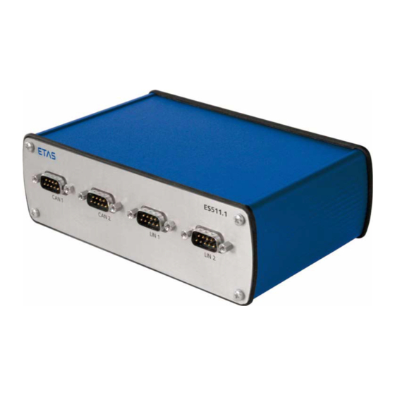
Housing Housing with ports on the front and rear of the device is used for the ES511.1. The sturdy metal housing has nonskid plastic feet and is intended for use in the lab, on the test bench and in the passenger cell of vehicles. -
Page 18: Back Panel
Fig. 2-3 Ports LEDs 2.6.1 Overview The ES511.1 has six LEDs, which indicate the operational, error and synchroni- zation state of the module, as well as with LEDs which display the functional state of the assigned Ethernet interface. Display ON/ER... -
Page 19: Led Display
2.6.2 LED Display What the ON/ER LED Indicates The module is assigned an ON/ER LED (see Fig. 2-2 on page 17). Display Operational State ON/ER Module is currently booting or booting was unsuccessful. Red, flashing, Firmware update in progress 500 ms on/ 500 ms off Green, flashing, Operational state: Standby... - Page 20 Hardware Description...
-
Page 21: Functional Description
An external power supply or the vehicle battery power the module. When the ES511.1 is connected to the operating voltage and there is an Eth- ernet connection at HOST, the module boots. If there is no Ethernet connec- tion, the module changes to “Standby.”... -
Page 22: Host" Port
The switchover takes place automatically. To fulfill the operation demands in the vehicle, the “HOST”, “ETH1”, “ETH2” and “ETH3” interfaces of the ES511.1 are each routed to an 8-pin port (Neu- trik ports). Sturdy Ethernet cables with Neutrik connectors (see section 6.2 on page 48) can be connected to the interfaces of the ES510.1 Network Mod-... -
Page 23: Power-Saving Feature
CAN Interface ("CAN 1", "CAN 2") The ES511.1 has two CAN interfaces. One each of the CAN interfaces is routed to the two 9-pin "CAN 1" and "CAN 2" connectors (DSUB socket) on the back panel. -
Page 24: Feature
120 Ohm for setting up CAN networks. LIN Interface ("LIN 1", "LIN 2") The ES511.1 has two LIN interfaces. One each of the LIN interfaces is routed to the two 9-pin "LIN 1" and "LIN 2" connectors (DSUB socket) on the back panel. -
Page 25: Flexray Interface ("Flexray A", "Flexray B")
Fig. 3-2 Power Supply at the LIN Bus The ES511.1 is not designed to power external nodes at the LIN bus. FlexRay Interface ("FLEXRAY A", "FLEXRAY B") The ES512.1 has one FlexRay interface with two channels. One each of the FlexRay channels is routed to the two 9-pin "FLEXRAY A"... -
Page 26: Module Network
Modules connected to the “HOST” interface (e.g. ES510.1) can synchronize the ES511.1 (SYNC-IN). If no synchronization signal is received at the “HOST” interface, the ES511.1 acts as master module for synchronization. The time synchronization unit of the ES51x master synchronizes the connected modules via the Ethernet lines. -
Page 27: Firmware Update
Firmware Update The firmware of the ES511.1 can be updated by the user so that future ver- sions of the module can also be implemented. The firmware is updated on the connected PC using service software. Note Neither the power supply nor the Ethernet connection can be interrupted... - Page 28 Functional Description...
-
Page 29: Getting Started
ES511.1. Applications 4.1.1 ES511.1 with XETK, ES590 and ES400 Modules For applications, the ES511.1 has direct access to XETK ECUs and to ECUs and vehicle buses via the interfaces of the connected measure modules. Application ES510 ES510... -
Page 30: Es510.1 With Es511 And Es512 Measure Modules
4.1.2 ES510.1 with ES511 and ES512 Measure Modules The ES510.1 has access to ECUs and vehicle buses for applications via the con- nected measure modules. Application Ethernet ES510 ES511 ES512 6-32V DC 6-32V DC 6-32V DC Ethernet Ethernet ES590/ FlexRay FlexRay ES591 Interface... -
Page 31: Wiring
ES511.1 and any devices connected to it. 4.2.1 “HOST” Port To connect the ES511.1 module with the PC (“HOST” port), you require the CBE500-3 cable or an Ethernet patch cable (see section 3.3 on page 21). To connect the ES511.1 with the PC •... -
Page 32: Eth1", "Eth2", "Eth3" Port
“ETH3” port), you require the CBE530-x cable or an Ethernet patch cable (see section 3.3 on page 21). Simple Module Network A simple module network consists of a single ES511.1 module with connected measure modules. ES51x measure modules are used in the following example. To connect an ES511.1 with ES51x measure modules •... -
Page 33: Fig. 4-3 Example Of A Module Network
With larger module networks, it is a good idea to make a sketch of the planned module network. The following figure shows an example of a module network with three cascaded ES51x modules. HOST ES51x ES511 ES512 ES51x ES511 ES512 ES51x Fig. -
Page 34: Configuring The Es511.1
4.3.1 Web Interface The web interface of the ES511.1 consists of a home page, a page for custom- ized configuration of the "HOST" interface for the "Auto / On Switch" func- tion and other pages with information on the status of the ES511.1. - Page 35 • The "HOST" interface is activated if the mod- ule is energized. Getting Started...
- Page 36 Getting Started...
-
Page 37: Technical Data
Technical Data The “Technical Data” chapter contains a summary of all technical data and the pin assignments of the ES511.1 module. General Data 5.1.1 Fulfilled Standards and Norms The module adheres to the following standards and norms: Norm Test EN 61326... -
Page 38: Mechanical Data
System Requirements 5.2.1 Hardware Operation of the ES511.1 requires a power supply voltage of 6 V to 32 V DC. 5.2.2 Ethernet Interface of the PC A PC with a free Ethernet interface (10/100 Mbit/s, Full Duplex) with an RJ-45 connection is required. -
Page 39: Electrical Data
Support in Application Software Inter- Application Classifi- INCA INTECRIO ASCET-RP face cation CAN Monitoring V6.2.1 CAN Output V6.2.1 V6.2.1 KWP2000 V6.2.1 V6.2.1 V6.2.1 LIN Monitoring V6.2.1 : MC: Measurement and Calibration Electrical Data 5.3.1 Interface „HOST“ Connection 10/100Base-T Ethernet; Full Duplex PC Card, 32 bit Protocol Ethernet Switching (Layer 2), IEEE802.3... -
Page 40: Power Supply
ECUs with Ethernet interface, ES510.1 Network Module, ES600 Network Module, ES400 Measurement Modules, ES51x Measurement Modules, ES590/ES591 Interface Modules ES910.2 Rapid Prototyping Module ES910.3 Rapid Prototyping Module, ES1000.3 System, Third party Ethernet devices : no adaptation to ETAS synchronization Technical Data... -
Page 41: Can Interfaces ("Can 1" And "Can 2")
5.3.4 CAN Interfaces ("CAN 1" and "CAN 2") CAN 1 and CAN 2 2 independent interfaces, galvanically isolated from each other and from the other interfaces Protocols CAN V2.0a (Standard Identifier), CAN V2.0b (Extended Identifier) Controller IP-Core (FPGA) Transceiver (Physical Layer) TJA1040 Transfer speed Max. -
Page 42: Pin Assignment
Pin Assignment Note All connectors are shown with a view of the interfaces of the ES510.1. 5.4.1 Interface „6-32V“ Fig. 5-1 Interface „6-32V“ Signal Meaning Reserved UBATT+ Supply voltage, plus Ground Ground Technical Data... -
Page 43: Interface „Host
5.4.2 Interface „HOST“ Signal Meaning ETH1_RX+ Received data, plus ETH1_RX- Received data, minus ETH1_TX+ Send data, plus n.c. Reserved n.c. Reserved ETH1_TX- Send data, minus n.c. Reserved n.c. Reserved ETH1_GND Ground, interface „HOST“ 5.4.3 Interface „ETH1“ Signal Meaning ETH2_TX+ Received data, plus ETH2_TX- Received data, minus ETH2_RX+... -
Page 44: Interface „Eth2
5.4.4 Interface „ETH2“ Signal Meaning ETH3_TX+ Received data, plus ETH3_TX- Received data, minus ETH3_RX+ Send data, plus n.c. Reserved n.c. Reserved ETH3_RX- Send data, minus n.c. Reserved n.c. Reserved ETH3_GND Ground, interface „ETH2“ 5.4.5 Interface „ETH3“ Signal Meaning ETH4_TX+ Received data, plus ETH4_TX- Received data, minus ETH4_RX+... -
Page 45: Interface „Can 1
5.4.6 Interface „CAN 1“ Signal Meaning n.c. Reserved CAN 1_L CAN LOW CAN 1_UBatt- CAN GND n.c. Reserved CAN 1_Shield Cable shield n.c. Reserved CAN 1_H CAN HIGH n.c. Reserved CAN 1_UBatt+ CAN UBATT 5.4.7 Interface „CAN 2“ Signal Meaning n.c. -
Page 46: Interface „Lin 1
5.4.8 Interface „LIN 1“ Signal Meaning n.c. Reserved n.c. Reserved LIN 1_UBatt- LIN GND n.c. Reserved LIN 1_Shield Cable shield n.c. Reserved LIN 1 n.c. Reserved LIN 1_UBatt+ LIN UBATT 5.4.9 Interface „LIN 2“ Signal Meaning n.c. Reserved n.c. Reserved LIN 2_UBatt- LIN GND n.c. -
Page 47: Cable And Accessories
Cable and Accessories The "Cables and Accessories" chapter contains an overview of the available cables and accessories. Power Supply Cable CBP510-2 0000 F 00K 106 273 Power Supply Cable Side A Side B Fig. 6-1 CBP510-2 Cable Side A Side B Signal Plug Signal... -
Page 48: Ethernet Cable
Ethernet Cable Note You can also use Ethernet patch cables (1:1, twisted pair, Cat5) in limited environmental conditions (e.g. in the lab). 6.2.1 CBE500-3 Cable Fig. 6-2 CBE500-3 Cable Product Length Order Number CBE500-3 F 00K 106 275 6.2.2 CBE530-x Cable Fig. -
Page 49: Can-/ Lin-/ Flexray Cable
CAN-/ LIN-/ FlexRay Cable CBH500-2 F 00K 106 276 0000 CAN/ LIN/FLX Fig. 6-4 CBH500-2 Cable Product Length Order Number CBH500-2 F 00K 106 276 6.3.1 CAN Terminating Resistor 120 Ohm Fig. 6-5 CBCX131-0 Terminating Resistor Product Length Order Number CBCX131.1-0 F 00K 103 786 Cable and Accessories... - Page 50 Cable and Accessories...
-
Page 51: Ordering Informationen
Ordering Informationen ES511.1 Order Name Short Name Order Number ES511.1 CAN and LIN Network Module, ES511.1 F 00K 106 450 including cable CBP510-2 Accessoires 7.2.1 Power Supply Cables Order Name Short Name Order Number Power Supply Cable, Neutrik NC3FXX -... -
Page 52: Can Termination Resistor
7.2.4 CAN Termination Resistor Order Name Short Name Order Number CAN Termination Resistor 120 Ohm, CBCX131-0 F 00K 103 786 2xDSUB (9fc+9mc), 0 m Ordering Informationen... -
Page 53: Appendix: Troubleshooting Problems
Error LEDs Please observe the LEDs which provide information on the functions of the interface and the ES511.1 (see the chapter 2.6 on page 18) to be able to judge the operational state of the ES511.1 as well as troubleshooting measures. -
Page 54: Problems And Solutions
Windows XP and Vista systems. Network security policies, however, may request the APIPA mechanism to be disabled. In this case, you cannot use a network adapter which is configured for DHCP to access ETAS hardware. The ETAS Network Manager displays a warning message. -
Page 55: Search For Ethernet Hardware Fails
Whenever you switch from a DHCP company LAN to the ETAS hardware net- work, it takes at least 60 seconds until ETAS hardware can be found. This is caused by the operating system’s switching from the DHCP protocol to APIPA, which is being used by the ETAS hardware. - Page 56 Cause: Device driver for network card not in operation It is possible that the device driver of a network card is not running. In this case you will have to deactivate and then reactivate the network card. To deactivate and reactivate the network card: •...
-
Page 57: Personal Firewall Blocks Communication
Ethernet hardware at all, although the configuration parameters are correct. Certain actions in ETAS products may lead to some trouble if the firewall is not properly parameterized, e.g. upon opening an experiment in ASCET or search- ing for hardware from within INCA or HSP. - Page 58 ETAS application, source ports 17099 through 18020, destination ports 17099 through 18020 • Outgoing TCP/IP connections to the network configured for the ETAS application, destination ports 18001 through 18020 Note The ports that have to be used in concrete use cases depend on the hard- ware used.
- Page 59 To unblock a product: • In the "Windows Security Alert" dialog win- dow, click on Unblock. The firewall no longer blocks the ETAS prod- uct in question (in the example: ASCET). This decision survives a restart of the program, or even the PC.
- Page 60 This tab lists the exceptions not blocked by the firewall. Use Add Program or Edit to add new programs, or edit existing ones. • Make sure that the ETAS products and ser- vices you want to use are properly configured exceptions. –...
- Page 61 *.ini files are modified during opera- tion. The ETAS software has to be installed by an administrator anyway. It is recom- mended that the administrator assures that the ETAS program/processes are added to the list of the Windows XP firewall exceptions, and selected in that list, after the installation.
- Page 62 • Click OK to close the window. An administrator has to select the respective ETAS software in the "Exceptions" tab of the "Windows Firewall" dialog window to avoid further problems regarding hardware access with that ETAS product.
-
Page 63: Etas Contact Addresses
Germany WWW: www.etas.com ETAS Subsidiaries and Technical Support For details of your local sales office as well as your local technical support team and product hotlines, take a look at the ETAS website: ETAS subsidiaries WWW: www.etas.com/en/contact.php ETAS technical support WWW: www.etas.com/en/hotlines.php... - Page 64 ETAS Contact Addresses...
-
Page 65: List Of Figures
Block Diagram..................21 Fig. 3-2 Power Supply at the LIN Bus..............25 Fig. 4-1 ES511.1 with XETK, ES590 and ES400 Modules ........29 Fig. 4-2 ES510.1 with ES511 and ES512 Measure Modules ........30 Fig. 4-3 Example of a Module Network ..............33 Fig. -
Page 67: Index
Basic Safety Instructions 7 mechanical 38 Block diagram 21 Bus Terminating Resistor, CAN- 24 Bus termination resistor, CAN 25 Electrical data 39 ETAS Contact Addresses 63 ETAS device synchronization 26 Cable 47 Ethernet Cable 48 Cable CBE500-3 48 Ethernet Cables 51... - Page 68 Operation conventions 12 Feature 24 Use-Case 12 Features 15 Ordering Informationen 51 Ethernet switch 21 Firmware update 27 Package contents 13 Phase shift 26 Getting started 29 Pin Assignment 42 Ports 17 Power Supply 40 Hardware Power supply 21 system requirements 38 Power Supply Cable 47 Hardware description 15 Power Supply Cables 51...
- Page 69 Waste Electrical and Electronic Equipment WEEE 10 WEEE take-back system 10 Wiring 31 Index...
Need help?
Do you have a question about the ES511.1 and is the answer not in the manual?
Questions and answers