
Related Manuals for Robotnik SUMMIT XL


Summary of Contents for Robotnik SUMMIT XL
- Page 1 SUMMIT XL MOBILE PLATFORM SYSTEM ELEMENTS MAINTENANCE MANUAL RBTNKDOC160609A Robotnik Automation SLL, Spain ...
-
Page 2: Table Of Contents
RBTNKDOC160609A System Elements and Maintenance Manual SUMMIT XL mobile platform Contents 1. Introduction 2. External Elements 2.1 Motor wheels 2.2 Motor Drivers 2.3 Control Panel 2.4 Axis Camera (optional) 2.5 Hokuyo Laser Range Finder (optional) 3. Internal Elements 3.1 Embedded PC 3.2 Wireless Router 3.3 DC/DC 12VDC & 5VDC 3.4 Terminals & Fuses 3.4.1 Initial setup of the fuses 3.5 FPU Pixhawk (optional) 4. Manual Controls 4.1 DualShock controller 5. Battery and Charger 5.1 LiFePO4 battery pack 5.1.1 LiFePO4 Cell 5.1.2 Protection circuit module 5.2 LiFePO4 Smart Charger 6. Communication Diagram 7. Maintenance Summary 8. Basic Drawings 2 ... -
Page 3: Introduction
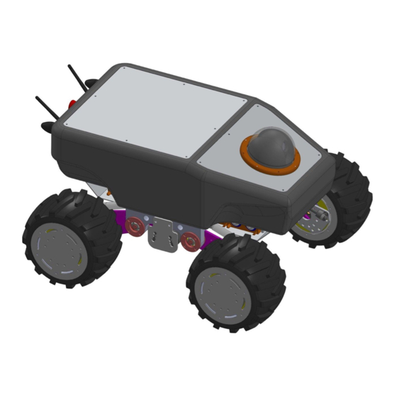
RBTNKDOC160609A System Elements and Maintenance Manual SUMMIT XL mobile platform 1. Introduction This Manual describes the main parts of the SUMMIT XL mobile robot, as well as how are they assembled. Every main piece includes a little description of the mechanical ... - Page 4 RBTNKDOC160609A System Elements and Maintenance Manual SUMMIT XL mobile platform Figure 2 – Main parts of SUMMIT XL robot, rear view The main parts that form the robot are: Housing : I t is made of fiber glass and holds the upper and rear covers. The ...
-
Page 5: Motor Wheels
brushed motors. This kind of rubber tire is specially made for Robotnik, so contact us if you need to ... -
Page 6: Motor Drivers
top. The drivers are programmed at Robotnik with specific a settings for each motor. The ... -
Page 7: Control Panel
RBTNKDOC160609A System Elements and Maintenance Manual SUMMIT XL mobile platform 2.3 C ontrol Panel The robot presents in its back cover several buttons, indicators and connectors: Figure 5 Control panel EMERGENCY STOP will disable the drivers and stop the robot. C AUTION ... -
Page 8: Axis Camera (Optional)
RBTNKDOC160609A System Elements and Maintenance Manual SUMMIT XL mobile platform 2.4 A xis Camera (optional) Figure 6 – Axis PTZ camera CAMERA AXIS P5514 PTZ Dome Network Camera Image sensor 1/2.3” progressive scan CMOS 3.8–42.9 mm, F1.4–2.1 Horizontal angle of view: 59.2°–5.2° Lens Autofocus, Autoiris Minimum Color: 0.7 lux at 30 IRE F1.4 illumination B/W: 0.08 lux at 30 IRE F1.4 Eflip, Autoflip, 100 preset positions Pan: 360° (with autoflip), Pan/tilt/zoom 1.8°–100°/s Tilt: 180°, 1.8°–100°/s 12x optical zoom, 10x digital zoom, total 120x zoom Limited guard tour, Control queue Video Resolution 1280x720 to 320x180 H.264 (MPEG4 Part 10/AVC) Baseline, Main and High Profiles ... -
Page 9: Hokuyo Laser Range Finder (Optional)
RBTNKDOC160609A System Elements and Maintenance Manual SUMMIT XL mobile platform Table 1 – AXIS P5514 features The camera is powered from the 12VDC DC/DC but can directly powered with an Axis High Power over Ethernet (High PoE) midspan, allowing Axis network video products to receive data and power over the same Ethernet cable. 2.5 Hokuyo Laser Range Finder (optional) The robot can be equipped with several models with our specific adaptors. Below you ... -
Page 10: Internal Elements
RBTNKDOC160609A System Elements and Maintenance Manual SUMMIT XL mobile platform 3. Internal Elements The following figure shows other nonmechanical components to be in consideration for maintenance tasks. Figure 7 – Summit XL inside view ... -
Page 11: Embedded Pc
RBTNKDOC160609A System Elements and Maintenance Manual SUMMIT XL mobile platform 3.1 Embedded PC The main board is a Mitac PD10BI MT with Intel Bay Trail J1900 Quad core processor and miniITX form factor. It can be easily replaced by other boards if needed. The ... - Page 12 RBTNKDOC160609A System Elements and Maintenance Manual SUMMIT XL mobile platform Audio ● 2 + 2 Channel High Definition Audio ( HD Audio) using a Realtek* ALC888S audio codec supporting: ● Analog stereo lineout (back panel jack) ● Inchassis stereo speakers support (3 W/3 Ω via an internal header) ● S/PDIF digital audio output (internal header) ● DMIC digital microphone input (internal header) ● Analog linein (back panel jack) ● Front panel HD Audio/AC’97 headphones/mic support (internal header) ● 8channel (7.1) HD Audio via the HDOut interface Expansion ● PCI Express 1.0a x1 addin card connector Option: PCI 1 Express 1.0a x4 addin card connector by 2 lanes Capability ● PCI Express Full/HalfMini Card slot 1 ● PCI Express HalfMini Card slot 1 Peripheral ● USB 2.0 front panel ports 5 Interfaces ●...
- Page 13 RBTNKDOC160609A System Elements and Maintenance Manual SUMMIT XL mobile platform ● 3pin system fan header with speed control Power ● DC connectivity via backpanel DC jack(2.5mm/ ID, 5.5mm/ OD) Requirement ● Internal 2 pin power connector Environment ● Operating Temperature: 0°C to +60°C ● Storage Temperature: 20°C to +70°C Safety ● CE ● FCC ● UL Table 3 – MITAC PD10BI features The embedded Linux PC is located in the middle of the robot, under the Edimax ...
-
Page 14: Wireless Router
RBTNKDOC160609A System Elements and Maintenance Manual SUMMIT XL mobile platform 3.2 Wireless Router Figure 9 – EDIMAX BR6428nC The huge 9dB antennas are replaced with smaller 5dB antennas. Technical Specification ● Wireless Data Transfer Rate: 802.11n: 300Mbps ● Supports router, access point & range extender modes ● Port triggering for special applications ● DDNS and SIP•Guest network ● Virtual server and DMZ hosting ● MAC/IP filter and URL blocking ● Static routing ● UPnP architecture ●... -
Page 15: Dc/Dc 12Vdc & 5Vdc
RBTNKDOC160609A System Elements and Maintenance Manual SUMMIT XL mobile platform 3.3 DC/DC 12VDC & 5VDC There is a 150W 12V DC/DC to provide a stable power supply for the electronic elements (PC, Axis camera, external power,…). ... -
Page 16: Terminals & Fuses
RBTNKDOC160609A System Elements and Maintenance Manual SUMMIT XL mobile platform 3.4 Terminals & Fuses Figure 12 Fuses At the picture you can see the DIN rail the following fuses: ● Fuse F0: 15A (blue) Back panel charge connector & switch S1. ● Fuse F1: 40A (orange) Main fuse, connected to battery directly. ● Fuse F2: 15A (blue) driver 1. ● Fuse F3: 15A (blue) driver 2. ● Fuse F4: 15A (blue) driver 3. ● Fuse F5: 15A (blue) driver 4. ● Fuse F6: 10A (red) 12V DC/DC converter INPUT. ● Fuse F7: 7.5A (brown) 12V DC/DC converter OUTPUT (+12V). ● Fuse F8: 2A (grey) Back panel 12V output (from DC/DC converter). ●... -
Page 17: Initial Setup Of The Fuses
RBTNKDOC160609A System Elements and Maintenance Manual SUMMIT XL mobile platform 3.4.1 Initial setup of the fuses After unpacking the robot, you have to insert fuses from battery and back panel in the fuse holder before turning on the robot. Important: E lectrical damage danger. Check the power ON/OFF is in OFF position ... -
Page 18: Fpu Pixhawk (Optional)
RBTNKDOC160609A System Elements and Maintenance Manual SUMMIT XL mobile platform 3.5 FPU Pixhawk (optional) The Pixhawk FPU is used as an IMU (Inertial Measurement Unit) to better estimate the robot position, using the Pixhawk integrated gyroscope and accelerometers. Figure 15 Pixhawk FCU Key Features: ... -
Page 19: Manual Controls
RBTNKDOC160609A System Elements and Maintenance Manual SUMMIT XL mobile platform Pixhawk is connected to the PC using a FTDI_USBtoUART cable on the TELEM2 port. The following table shows the mapping between Pixhawk TELEM2 pins and FTDI ... -
Page 20: Battery And Charger
RBTNKDOC160609A System Elements and Maintenance Manual SUMMIT XL mobile platform Figure 16 – Sony DualShock controller 5 . Battery and Charger The robot receives the power supply from a LiFePO4 battery pack. It is composed of ... -
Page 21: Lifepo4 Battery Pack
RBTNKDOC160609A System Elements and Maintenance Manual SUMMIT XL mobile platform 5.1 LiFePO4 battery pack Figure 17– LiFePo4 Battery Pack The battery pack is composed of eight LiFePO4 cells and a protection circuit module. The whole package is protected with shrinkable tube. The batteries must be kept clean and dry in order to avoid escape currents. Check ... -
Page 22: Lifepo4 Cell
RBTNKDOC160609A System Elements and Maintenance Manual SUMMIT XL mobile platform 5.1.1 LiFePO4 Cell Figure 18 LiFePo4 cell Specifications: ● Normal capacity 15000mAh ● Normal voltage 3.2V ● Inter impedance <8mOhms ● Maximum continuous Discharge Current 10C(150A) ● Charging Temperature: 10 – 45ºC (14 – 113º F) ● Discharging Temperature: 20 – 60ºC (14 – 140ºF) ● Cycle Performance: >2000 (80% of initial capacity at 1C rate) ● Standard Charging current: 1C (15A), Max. 5C (75A) ● Weight: 500g 5.1.2 Protection circuit module Figure 19– Protection circuit module 22 ... - Page 23 RBTNKDOC160609A System Elements and Maintenance Manual SUMMIT XL mobile platform 24V BMS 8CELLS 30A Item 8 series balancing guard shield Over charge protection (V) 3.95±0.025 Over charge recovery (V) 3.80±0.05 Over discharge voltage (V) 2.2±0.1 Over discharge recovery (V) Cut load or charge Normal working current (A) Over current protection (A) Internal resistance (m/ohm) <30 Charging balancing current (mA)
-
Page 24: Lifepo4 Smart Charger
RBTNKDOC160609A System Elements and Maintenance Manual SUMMIT XL mobile platform 5.2 LiFePO4 Smart Charger Figure 20– LiFePo4 Smart Charger The Smart Charger is designed for rapidly charge 29.2V (8 cells) LiFePO4 Battery pack. I MPORTANT: CHECK POWER SELECTION BEFORE PLUGGING IT Specifications: ● INPUT o 115/230VAC Worldwide power input support by ... - Page 25 RBTNKDOC160609A System Elements and Maintenance Manual SUMMIT XL mobile platform ● LEDs Status o LED1 RED: AC Power on o LED2 RED: Charging o LED2 GREEN: Charging completed or battery not connected ● Temperature o Operating temperature: 5ºC ~ +40ºC o Storage temperature: 10ºC ~ +70ºC Caution: The charger is designed for indoor use only. ● The charger should be placed horizontally and operate in well ventilated ● condition, avoid humidity and keep it away from inflammable explosive material. The aluminum case is a heat sink, do not cover it. ● Do not disassemble the charger due to high voltage inside. ● Figure 21– LiFePo4 Smart Charger Front view Figure 22– LiFePo4 Smart Charger Rear view If you have trouble charging batteries check these: 25 ...
- Page 26 RBTNKDOC160609A System Elements and Maintenance Manual SUMMIT XL mobile platform Check charger Power Switch Charger LED1 is off Check charger Input Fuse If battery is close to 29.2V is already charged Check if charger connector is properly attached Charger LED2 is green at the robot back panel Check charger Output Fuse Check Summit XL Fuse F0 Table 6 – Charging trouble tips 26 ...
-
Page 27: Communication Diagram
RBTNKDOC160609A System Elements and Maintenance Manual SUMMIT XL mobile platform 6. Communication Diagram The following figure shows the communication diagram existing inside the robot. The functionality of the system can be further extended by using the free Ethernet ports and free USB port (inside and outside). ... -
Page 28: Maintenance Summary
RBTNKDOC160609A System Elements and Maintenance Manual SUMMIT XL mobile platform 7. Maintenance Summary In the previous parts some main parts of the vehicle and components that need maintenance or only supervision have been mentioned. The following table ... -
Page 29: Basic Drawings
RBTNKDOC160609A System Elements and Maintenance Manual SUMMIT XL mobile platform 8. Basic Drawings Figure 24– External robot drawings 29 ...
Need help?
Do you have a question about the SUMMIT XL and is the answer not in the manual?
Questions and answers