Table of Contents
Advertisement
Quick Links
The information in this manual is proprietary and confidential to RFL Electronics Inc. Any re-
production or distribution of this manual, in whole or part, is expressly prohibited, unless writ-
ten permission is given by RFL Electronics Inc.
This manual has been compiled and checked for accuracy. The information in this manual
does not constitute a warranty of performance. RFL Electronics Inc. reserves the right to re-
vise this manual and make changes to its contents from time to time. We assume no liability
for losses incurred as a result of out-of-date or incorrect information contained in this manual.
RFL 9300
September 5, 2007
INSTRUCTION MANUAL
Charge Comparison System
U.S. Patent Nos. 4,939,617, 5,111,358, and 5,150,270
(Foreign Patents Pending)
RFL Electronics Inc.
353 Powerville Road ● Boonton Twp., NJ 07005-9151 USA
Tel: 973.334.3100 ● Fax: 973.334.3863
Email:
sales@rflelect.com
Publication Number MC9301C
Printed in U.S.A.
Revised September 5, 2007
RFL 9300
NOTICE
●
www.rflelect.com
i
RFL Electronics Inc.
(973) 334-3100
Advertisement
Table of Contents

Summary of Contents for RFL Electronics RFL 9300
- Page 1 (Foreign Patents Pending) NOTICE The information in this manual is proprietary and confidential to RFL Electronics Inc. Any re- production or distribution of this manual, in whole or part, is expressly prohibited, unless writ- ten permission is given by RFL Electronics Inc.
- Page 2 WARRANTY The RFL 9300 comes with a ten-year warranty from date of shipment for replacement of any part which fails during normal operation. RFL will repair or, at its option, replace components that prove to be defective at no cost to the Customer. All equipment returned to RFL Electronics Inc. must have an RMA (Return Material Au- thorization) number, obtained by calling the RFL Customer Service Department.
- Page 3 BY QUALIFIED PERSONS. WARNING: The equipment described in this manual contains high voltage. Exercise due care during operation and servicing. Read the safety summary on the reverse of this page RFL 9300 RFL Electronics Inc. September 5, 2007 (973) 334-3100...
- Page 4 The instructions contained in these warnings and This will remove any dangerous voltages that cautions must be followed exactly. may still be present after power is removed. RFL 9300 RFL Electronics Inc. September 5, 2007 (973) 334-3100...
-
Page 5: Table Of Contents
5.4 VENTILATION................................5 5.5 ELECTRICAL CONNECTIONS ..........................5 5.6 MODEM CONNECTIONS ............................10 5.7 FIBER OPTIC CONNECTIONS..........................11 5.8 DIRECT DIGITAL CONNECTIONS ........................11 5.9 IRIG-B CLOCK CONNECTIONS ..........................11 RFL 9300 RFL Electronics Inc. September 5, 2007 (973) 334-3100... - Page 6 6.2 CONTROLS AND INDICATORS ..........................1 6.3 START-UP PROCEDURES............................1 6.4 DISPLAY MODES ..............................14 6.5 ACCESSING THE RFL 9300 FROM A PC OR TERMINAL .................. 32 6.6 RFL 9300 ADDRESSING ............................61 6.7 DESCRIPTION OF INSTANTANEOUS OVERCURRENT BACKUP TRIP ALGORITHM and INVERSE TIME OVERCURRENT BACKUP TRIP ALGORITHM......................
- Page 7 SECTION 24: SINGLE POLE CHASSIS ..........................1 24.1 DESCRIPTION................................1 24.2 CONROLS AND INDICATORS ..........................1 24.3 THEORY OF OPERATION - HARDWARE......................6 24.4 THEORY OF OPERATION - SOFTWARE ......................8 RFL 9300 RFL Electronics Inc. September 5, 2007 (973) 334-3100...
- Page 8 29.9 SQUELCH RULES..............................3 29.10 CHANNEL DELAY LIMITS........................... 6 29.11 TEST POINTS ................................7 SECTION 30: GLOSSARY OF TERMS ..........................1 SECTION 31: INDEX ................................1 SECTION 32: SCHEMATICS..............................1 Application Notes RFL 9300 RFL Electronics Inc. September 5, 2007 viii (973) 334-3100...
-
Page 9: List Of Illustrations
Figure 3-9. Currents before pre-fault subtraction........................8 Figure 3-10. Currents after pre-fault subtraction........................8 Figure 3- 11. Operation of the RFL 9300’s UHS circuit during an internal fault ..............10 Figure 3-12. Operation of the RFL 9300’s UHS circuit during and external fault ............... 10 Figure 3-13. - Page 10 Figure 6-4. Front Panel RS-232 cable connections....................... 32 Figure 6-5. Cable connections between RFL 9300 and PC or terminal using XON/XOFF handshaking ......33 Figure 6-6. APRIL commands for use with RFL 9300 (for two-terminal and three-terminal mode) ........35 Figure 6-7.
- Page 11 Figure 9-1. RFL 9300 display module for horizontal chassis ....................1 Figure 9-2. Controls and indicators for display controller board, used in RFL 9300 display module ........3 Figure 9-3. Controls and indicators for oscillography board, used in RFL 93B DISPLAY module ........7 Figure 9-4.
- Page 12 Figure 19-1. Typical RFL 9300 power supply module ......................1 Figure 19-2. Component locator drawings, 50-watt power supply module ................6 Figure 19-3. 9300 PS 48/125 DC power supply module for RFL 9300 Charge Comparison System, (Assembly No. 106715-1; Schematic No. 106719-E)..........................7 Figure 20-1.
- Page 13 Figure 24-1. Typical RFL 9300 Single Pole Chassis, front panel view .................. 1 Figure 24-2. Typical RFL 9300 Single Pole Chassis, front panel view showing LED indicators .......... 2 Figure 24-3. Typical RFL 9300 Single Pole Chassis, rear panel view..................3 Figure 24-4.
- Page 14 Table 9-1. RFL 93B Display Module, general information ....................2 Table 9-2. Replaceable parts for display controller board, used in RFL 9300 display module. (Assembly No. 106325-2). 10 Table 9-3. Replaceable parts for oscillography board, used in RFL 9300 display modules (Assembly No. 106330)..13 Table 9-4.
- Page 15 Table 19-1. 9300 Power Supply Specifications ........................2 Table 19-2. Replaceable parts, 50-watt power supply module for RFL 9300 Charge Comparison System......4 Table 20-1. Replaceable parts, RFL 93B Relay I/O, Power/RS-232 board ................7 Table 20-2. Replaceable parts, RFL 93 Relay I/O module, Current Sense board..............9 Table 20-3.
- Page 16 LIST OF EFFECTIVE PAGES When revisions are made to the RFL 9300 Instruction Manual, the entire section where revisions were made is replaced. For the edition of this manual dated September 5, 2007, the sections are dated as follows: September 5, 2007...
- Page 17 Revised in accordance with ECO Nos. 9300-220, -225 and –226. 10-27-00 Revised Sections 0, 6, 7, 8, 9, and 27 in accordance with new en- 10-27-00 gineering documentation. RFL 9300 RFL Electronics Inc. September 5, 2007 xvii (973) 334-3100...
- Page 18 CAR# C9300-0089, and note from BH dated 1-28-03. (Revised Sections 7 and 22) Note: 15 Manuals printed at (10-20-04) incorporating the above changes to meet shipping require- ment but manual not released at this date. RFL 9300 RFL Electronics Inc. September 5, 2007 xviii...
- Page 19 Manual released incorporating all changes from 10-20-04 also 4-25-06 changes as per ECO 9300-289 with changes to Section 18, Section 32 (Schematics) added to CD version. 9-5-07 Warranty statement changed. 9-5-07 RFL 9300 RFL Electronics Inc. September 5, 2007 (973) 334-3100...
- Page 20 This page intentionally left blank RFL 9300 RFL Electronics Inc. September 5, 2007 (973) 334-3100...
-
Page 21: Section 1: Product Information
SECTION 1: PRODUCT INFORMATION Please see next page. RFL Electronics RFL 9300DCDR (973) 334-3100 1 - 1 Publication No. PI9300DCDR June, 2002... - Page 22 This page intentionally left blank RFL 9300 RFL Electronics Inc. September 5, 2007 (973) 334-3100...
- Page 23 If the net charge differs from zero by more than a small threshold level called the “bias”, and internal fault is The RFL 9300 does not require any AC line potential, and is declared and breaker trip signals are issued. This technique unaffected by possible problems associated with the AC has been patented.
- Page 24 There are two principle advantages of charge comparison compared to current differential relaying: 1. Greatly reduced communications throughput providing enhanced reliability. 2. Precise channel delay compensation is not required, making the RFL 9300 the relay of choice for SDH and SONET applications.
- Page 25 Figure 3. Block diagram, typical (3-pole) RFL 9300 equipped with modem RFL Electronics Inc. June 10, 2002 RFL 9300DCDR...
- Page 26 The concept of single pole tripping is to isolate only the faulted phase for single line to ground faults. Combined with single pole The RFL 9300 is designed to work over the following types reclosing, this relaying technique maintains system stability by...
- Page 27 RFL 9300 Digital Current Differential Re- The phase and residual currents are applied to the RFL 9300 lay to tolerate “differential delays” and sudden delay transi- auxiliary current transformers (ACTs) operating at almost tions better than other schemes.
- Page 28 See Figure 10.This fiber service unit is compliant to the ANSI Remote interrogation is available through an RS-232 port on C.37.94 specification. the rear of the RFL 9300. This port can be connected to any computer with a terminal emulation mode. DC Trip Current Sense...
- Page 29 Enter the update mode Exit the update mode Go to sequence-of-events menu 9300>_ Figure 11. APRIL commands for use with RFL 9300 (for two-terminal and three-terminal mode) Oscillography The oscillography board is an extension of the display controller. It is directly connected to the display controller through an 8-bit bi-direc- tional data bus and additional control lines.
- Page 30 There are 4,063 pos- MOUNTING sible combinations. The 3 pole RFL 9300 is three rack-units high (5.25 inches, or 13.3 cm) and mounts in a standard 19-inch rack or cabinet. FAULT DETECTOR SUPERVISION The single pole RFL 9300 is five rack-units (8.75 inches, or Any sudden change in current (such as magnitude or half- 22.25 cm) (See Figure 13 for mounting dimensions)
- Page 31 Figure 14. Mounting dimensions, RFL 9300 (3-pole relaying) vertical chassis. RS232 Figure 13. Mounting dimensions, RFL 9300 (3-pole relaying) horizontal chassis with optional functional test panel. RFL Electronics Inc. June 10, 2002 RFL 9300DCDR...
- Page 32 Figure 15. Rear views, typical RFL 9300 terminals RFL Electronics Inc. June 10, 2002 RFL 9300DCDR...
- Page 33 Aux1 Trip-1 Trip-2 Aux1 Trip-1 Trip-2 Aux1 Phase A Phase B Phase C Figure 16. Front View of RFL 9300 Single Pole Chassis Extension. 3.38’’ RFL 9300 Single Pole Option STATUS PHASE A PHASE B PHASE C THREE SINGLE TRIP...
- Page 34 0.1 ampere @ 125 Vdc. IRIG-B: System Alarm: One set of Form C (SPDT) contacts, rated 0.1 am- The display module in the RFL 9300 can be configured to accept pere @ 125 Vdc. either of the following two types of IRIG-B signals: 1.
- Page 35 RFL 9300 Charge Comparison Relay Ordering Guide BASE SYSTEM: MIXED CT RATIOS: The RFL 9300 relay is housed in a 19” rack mountable chas- The RFL 9300 relay must compare the same magnitudes of sis. The chassis is constructed utilizing plug in modules to current between all terminals.
- Page 36 RFL Electronics Inc. June 10, 2002 RFL 9300DCDR...
- Page 37 NOTES: RFL Electronics Inc. June 10, 2002 RFL 9300DCDR...
- Page 38 RFL Electronics Inc. 3 5 3 P o w e r v i l l e R o a d Boonton Twp., NJ 07005-9151 T e l : 9 7 3 . 3 3 4 . 3 1 0 0 F a x : 9 7 3 .
-
Page 39: Section 2: System Operation
This section provides a basic description of how the RFL 9300 Charge Comparison System operates. A block diagram of the RFL 9300 appears in Figure 2-1. After reading this section, refer to Section 24 if your system has the Single Pole Option. -
Page 40: Figure 2-1. Block Diagram, Rfl 9300 Charge Comparison System (Two Terminal)
CURRENT SENSE MAIN CONTACT PAIRS /6 IRIG-B DTT CONTACT PAIRS /2 RS-232 /2 RS-232 CONTROL /4 Figure 2-1. Block diagram, RFL 9300 Charge Comparison System (two terminal) RFL 9300 RFL Electronics Inc. October 29, 2001 2 - 2 (973) 334-3100... - Page 41 MULTI-LINE CONNECTIONS ARE INDICATED BY A SLASH FOLLOWED BY A NUMBER FOLLOWING THE SIGNAL NAME. FOR EXAMPLE, “ /4 “ INDICATES A FOUR LINE CONNECTION. Figure 2-1. Block diagram, RFL 9300 Charge Comparison System (two-terminal) - continued RFL 9300 RFL Electronics Inc.
-
Page 42: Communications Controller Module
A null word will be transmitted if there is nothing else to send. The RFL 93B CC at the remote RFL 9300 uses a hardware comparator and EPROM lookup table to test the CRC security of each received word. - Page 43 After the switchover, the RFL 9300 sends a message to the remote RFL 9300 , asking that it also switch to the other channel. In all other respects, hot standby operation is identical to single-channel modem operation.
-
Page 44: Channel Impairment Characteristics
3. Synchronous clock indicates that Channel 1 and Channel 2 have a common clock source. 2.4 CHANNEL IMPAIRMENT CHARACTERISTICS RFL 9300 terminals operate with different channel impairment characteristics, depending on how the terminal is configured. The following paragraphs describe the characteristics for direct digital, fiber optic, and single-channel modem interfaces. - Page 45 The RFL 93B CC uses three squelch rules to determine whether communication quality is below that required by the RFL 9300. They are identified as Squelch Rule 1, Squelch Rule 2, and Squelch Rule 3 (SQ1, SQ2, and SQ3): SQ1 blocks messages from going to the RFL 93B SV module, but does not alarm the module.
- Page 46 S/N and BER (Bit Error Rate) changes slightly with added equalization (2 dB). If the S/N is better than 16 dB, the dependability of the relay is 100 percent with a 3002 conditioned line. RFL 9300 RFL Electronics Inc.
-
Page 47: Supervisor Controller
The RFL 93B CC uses three squelch rules to determine whether communication quality is below that required by the RFL 9300 . They are identified as Squelch Rule 1, Squelch Rule 2, and Squelch Rule 3 (SQ1, SQ2, and SQ3): SQ1 blocks messages from going to the RFL 93B SV module, but does not alarm the module. - Page 48 The RFL 93B SV supplies the received DTT trip signal to the Oscillography Board through a dedicated hard- ware line. It also monitors the local RFL 9300 's DTT input port. The DTT input trip signals it detects are passed to the Communications Controller for transmission to the remote RFL 9300.
- Page 49 The RFL 93B SV monitors all trip signals originating at both the local and remote terminals. If the RFL 9300 is configured for three-pole trip operation and a trip signal (generated locally or remotely) is detected, a 150ms timer is started. If trips are detected on all phases before this timer expires, a three-phase trip is said to exist, and the reclose block output relay is energized for 50ms.
-
Page 50: Auxiliary Current Transformer (Act)
Module. The RFL 93B PC uses an equivalent 10-bit serial A/D converter to convert the analog signal to a digital value. The integral of all such “control” CT current samples taken during a half-cycle is computed when the half-cycle-ending zero-crossing time-tag is recorded. RFL 9300 RFL Electronics Inc. October 29, 2001... - Page 51 It is important to recognize this difference in order to understand CCS 3-terminal operation. The RFL 9300 will not store a CCD message in the local on-board buffer or transmit it to the remote station if either of the following occur: The CT current recorded during a given half-cycle interval is less than 0.5 A rms .
-
Page 52: Figure 2-2. Logic Diagram, Composite Fault Detector
2.7.2 STRONG-FEED TRIP (SFT) ALGORITHM The SFT algorithm detects strong internal faults. (See Figure 2-3.) The RFL 9300 enters a special LCCT (Local Current Comparison Trip) alarm mode if the SFT algorithm produces a trip enabled signal under the following conditions: The necessary fault detectors were not activated to cause a trip signal to be issued. -
Page 53: Figure 2-3. Logic Diagram, Strong-Feed Trips (For 2- And 3- Terminal Systems)
FAULT DETECTOR REMOTE (See Figure 2-2) TERMINAL Logic diagram, strong-feed trip for three terminal systems Figure 2-3. Logic diagram, strong-feed trips (for 2- and 3- terminal systems) RFL 9300 RFL Electronics Inc. October 29, 2001 2 - 15 (973) 334-3100... -
Page 54: Figure 2-4. Differential Characteristics For 9300 In 2- And 3- Terminal Modes
Differential Characteristic for 9300 in 3- terminal mode Figure 2-4. Differential Characteristics for 9300 in 2- and 3- terminal modes RFL 9300 RFL Electronics Inc. October 29, 2001... - Page 55 Receiving a UHST signal without the necessary fault detector conditions being satisfied, also will result in a WFT signal being echoed back to the sending RFL 9300. This will result in a faster trip response time, since the remote RFL 9300 does not have to wait for the zero crossing of the current waveform before it transmits the UHST signal.
-
Page 56: Figure 2-5. Logic Diagram, Weak-Feed Trip (For 2- And 3- Terminal Systems)
1. SIGNAL MUST BE VALIDATED FOR THREE TERMINAL SYSTEM. 2. MUST BE COMPOSITE FOR THREE TERMINAL SYSTEM. Figure 2-5. Logic diagram, weak-feed trip (for 2- and 3- terminal systems) RFL 9300 RFL Electronics Inc. October 29, 2001 2 - 18... -
Page 57: Figure 2-6. Logic Diagram, Switch-Into-Fault With Communications (2- And 3- Terminal Systems)
(See Figure 2-6). After a WCM message is received (validated WCM mes- sage in the case of a 3-terminal system) the RFL 9300 uses a special formula to adjust its time-tag. From that point on it is treated as a CCD message with zero value and run through the SFT algorithm. -
Page 58: Figure 2-7. Logic Diagram, Ultra High-Speed Trip
- 7.5A peak. The RFL 9300 sends a UHST signal to the remote RFL 9300 whenever the local station detects that the input current's peak value is +12 amperes or more for 2 ms. This results in a much faster trip response at the remote RFL 9300 for strong internal faults, since it doesn't have to wait for the current waveform's zero crossing to send the signal. -
Page 59: Figure 2-8. Logic Diagram For Open Conductor And Loss Of Load Algorithm
RFL 9300 is programmed. Note that when the RFL 9300 is programmed for trip on open conductor, this function issues a trip signal, not a trip enable signal. This is because the fault detectors probably will no longer be active when the Zone 2 timer expires. - Page 60 Instead “SBACTIVE” will appear on the display in place of ENABLED or DISABLED. This will inform the operator that stub bus is active and the relay has been forced into backup mode (See Figure 2-9). RFL 9300 RFL Electronics Inc. October 29, 2001...
-
Page 61: Figure 2-9. Logic Diagram, Stub-Bus Applications
RELAY TO SWITCH OPEN BACKUP MODE Tx MESSAGES TRANSMITTER TO REMOTE MESSAGES LWFT CCT-U MESSAGES RECEIVER FROM REMOTE LWFT CCT-U MESSAGES Figure 2-9. Logic diagram, stub-bus applications RFL 9300 RFL Electronics Inc. October 29, 2001 2 - 23 (973) 334-3100... - Page 62 The "ping-pong" method of measuring channel delay has one basic limitation. If the sending and receiving paths have different delays they will not be detected. The RFL 9300 uses a method based on the measurement of zero crossings of the phase current waveforms to correct this. It is called "DML" (Delay Measurement based on Load current).
-
Page 63: Backup Mode Operation
2.8 BACKUP MODE OPERATION Except for the open conductor algorithm, the RFL 9300 cannot execute any of its charge comparison protection algorithms if the communications channel to the remote station is disrupted. If a communications failure occurs, some degree of protection is still provided. Whenever the RFL 93B CC Communications Controller detects a communications failure, it signals the phase controllers to enter the backup mode. -
Page 64: Direct Transfer Trip (Dtt)
If any system or communications alarms are active, the RFL 93B SV will signal the display controller. Each alarm message has an error number that appears on the display. The display controller monitors the trip sig- nals; it generates alarm messages if any error conditions are detected. RFL 9300 RFL Electronics Inc. October 29, 2001... - Page 65 3-second LED test will be triggered on both. After the LED test is completed, the remaining modules except for the comms cards in the RFL 9300 will execute a 3-second LED test. If there are any active trip sig- nals on the main chassis, a “TRIP ACTIVE”...
-
Page 66: Figure 2-11. Logic Diagram, Trip Seal-In
DETECTED BY PC 200 ms RE-TRIGGERABLE ONE-SHOT PC FAULT CLEAR DETECTORS BREAKER OPEN RFL 9300 Circuit Breaker a. Logic diagram b. Trip circuit schematic Figure 2-11. Logic diagram, trip seal-in RFL 9300 RFL Electronics Inc. October 29, 2001 2 - 28... -
Page 67: Figure 2-12. Logic Diagram, Dtt Trip Seal-In
ALARM NO. 24 (0.5A OPTIONAL) DTT-2 RECEIVED DTT 100 ms DTT-1 RETRIGGERABLE TIMER a. Logic diagram RFL 9300 Lockout Relay (DTT) (DTT) b. Trip circuit schematic Figure 2-12. Logic diagram, DTT trip seal-in RFL 9300 RFL Electronics Inc. October 29, 2001... -
Page 68: Oscillography Board
The RFL 9300 has the ability to synchronize its internal real time clock with an external IRIG-B clock source. The IRIG-B signal enters the RFL 9300 via a BNC connector on the Relay I/O module. The signal is then routed to the oscillography board, which demodulates the IRIG-B signal and feeds it to an embedded controller, which is also used for the oscillography feature. - Page 69 Since each phase controller will base the test on its on-board crystal, the RFL 9300 has four independent crystal based frequency discriminators monitoring this clock. If a phase controller de- tects an error in the clock, it will reset and attempt to re-initialize.
-
Page 70: Section 3: Applications
The RFL 9300 is based on the principle of Conservation Of Charge, which is independent of frequency. Its op- eration is not affected by the off-normal frequencies that may appear during the post-fault period. These off- normal frequencies may be caused by series capacitors or other power system parameters. -
Page 71: Figure 3-1. Voltage Inversion
The RFL 9300 is unaffected by phase unbalance because it operates on a per-phase basis; each phase current and the 3I 0 current are compared separately. -
Page 72: Very Short Lines
F1 and one at F2. Current-based relays compare the currents (or charges) at the local station to those at the remote station. This makes it easy to tell whether the fault is internal or external to the protected line. RFL 9300 RFL Electronics Inc. August 25, 2000... -
Page 73: Effect Of Infeed/Outfeed
Bus R and outfeed current can flow through terminal M. This would cause a distance or directional relay at terminal M to see the fault as external. They will not clear the fault until relay R opens. Figure 3-5. Strong bus tie RFL 9300 RFL Electronics Inc. August 25, 2000... -
Page 74: High-Resistance Ground Fault
Figure 3-6. High-resistance ground fault with heavy through-load, causing an outfeed condition Figure 3-7 is a polar diagram with the currents on the faulted phase in Figure 3-6 plotted. Since the RFL 9300 has a "rainbow" characteristic, the relay correctly trips. -
Page 75: Prefault Load Subtraction
4ms communications error margin to the relay. When the RFL 9300 relay is configured for 3-terminal operation its control algorithms, for the most part, are based on transient fault currents obtained using prefault load subtraction. -
Page 76: Figure 3-8. Prefault Load Subtraction Eliminates Generator Angles
Iload – pre-fault load → JXI-thevenin JXr-thevenin ↑ Iml” JXm-thevenin E1” Er” Em” e) Vf set equal to prefault voltage at fault Figure 3-8. Prefault load subtraction eliminates generator angles RFL 9300 RFL Electronics Inc. August 25, 2000 3 - 7 (973) 334-3100... -
Page 77: Figure 3-9. Currents Before Pre-Fault Subtraction
Figure 3-9. Currents before pre-fault subtraction Figure 3-10. Currents after pre-fault subtraction RFL 9300 RFL Electronics Inc. August 25, 2000 3 - 8 (973) 334-3100... -
Page 78: Ultra High-Speed Tripping
3.8 ULTRA HIGH-SPEED TRIPPING The RFL 9300's UHS (Ultra High-Speed) circuit provides a trip decision in as little as 7 ms, when the RFL 9300 is using a 56-Kbps or fiber channel. (Actual breaker tripping takes about 4 ms longer; this allows for the auxiliary relay's pick-up time). -
Page 79: Figure 3- 11. Operation Of The Rfl 9300'S Uhs Circuit During An Internal Fault
Time window of 6 ms that looks for – (11A – bias setting) peak sample to block UHS. Figure 3- 11. Operation of the RFL 9300’s UHS circuit during an internal fault Correct blocking during this time interval. (Only 1 sample equal to – (11A – bias... -
Page 80: Saturated Main Current Transformers
"Transient factor" for ground faults. This is equal to (1 + X L /R) where (L/R) is the primary system time constant. Figure 3-13. Saturated main current transformers during close-in internal fault RFL 9300 RFL Electronics Inc. August 25, 2000... - Page 81 CT's rated "C200" should be used. 3.9.2 EXTERNAL FAULT CALCULATION The RFL 9300 tolerates less CT saturation on external faults than it does on internal faults. The UHS circuit operates (blocks) correctly on the odd half-cycles (1st, 3rd, 5th, etc). However, the CCD (Charge Comparison Data) on all half-cycles may trip incorrectly.
-
Page 82: Figure 3-14. External Fault With Very Severe Ct Saturation At One End
One-line diagram b. Current waveforms Figure 3-14. External fault with very severe CT saturation at one end RFL 9300 RFL Electronics Inc. August 25, 2000 3 - 13 (973) 334-3100... - Page 83 (about 75 degrees) than source impedance (as high as 85 degrees, or more). To select the proper CT class for external faults, take the larger of the calculated kneepoint voltages (V ), and divide it by four. The next-higher CT class will be adequate for RFL 9300 operation on external faults.
-
Page 84: Weak Infeed Applications
This is referred to as a "tripping" philosophy. Since the RFL 9300 uses a tripping philosophy for enhanced security, special provisions must be incorporated to assure proper operation in weak-feed applications. -
Page 85: Reclose Blocking For Three-Phase Faults
The RFL 9300 can be applied to underground cables by setting the phase bias and ground bias levels high enough to provide security in the presence of line charging currents (or the discharging currents present during a fault). The minimum bias setting is 1.0 amperes;... -
Page 86: Figure 3-16. Double Line-To-Ground (Dlg) Fault
Figure 3-16. Double line-to-ground (DLG) fault (May look like three-phase fault to protection schemes that are not per-phase.) RFL 9300 RFL Electronics Inc. August 25, 2000 3 - 17 (973) 334-3100... -
Page 87: Stub-Bus Protection
To cover all the conditions shown in Figure 3-17, the breakers at the local station must be cleared, and the breakers at the remote station(s) must not be cleared. The RFL 9300 meets these requirements as follows: When the disconnect switch is opened at the local station, the relay immediately enters stub-bus active mode. -
Page 88: Figure 3-17. Sub-Bus Protection
(2-terminal system) Remote terminals are double-breaker, or a combination of double breaker and single breaker, with or without a tapped load (3-terminal system) Figure 3-17. Sub-bus protection RFL 9300 RFL Electronics Inc. August 25, 2000 3 - 19 (973) 334-3100... -
Page 89: Tapped Load
6 to 10percent. This means that low-side phase faults are at least ten times the magni- tude of the rated current. The RFL 9300 can be applied to tapped lines by raising the bias level so that the RFL 9300 will not respond to low-side faults. -
Page 90: Figure 3-19. Transformer In-Rush
Figure 3-19. Transformer in-rush In general, this makes the RFL 9300 suitable for all tapped lines, except for those applications where the trans- former allows significant zero-sequence current to flow from the high-side to feed low-side faults. An example of this is the wye-wye transformer configuration shown in Figure 3-20, where both sides are solidly grounded. -
Page 91: Figure 3-20. Zero-Sequence Current Flows Through Transformer
"infinite" source. It is also assumed that all the limiting impedance for the low-side fault is due to the trans- former impedance. This will introduce a safety factor of about 10-percent into the calculations. Figure 3-21. Typical tapped line application RFL 9300 RFL Electronics Inc. August 25, 2000... - Page 92 The phase bias should be set to a value equal to at least three times the maximum let-through current; this will take care of transient over-reach due to dc offset. With the phase bias set at 6 amperes, the RFL 9300 can tolerate a let-through current of 2 amperes, so a setting of 6A phase bias is appropriate for this application.
- Page 93 If the tap transformer blocks the flow of zero-sequence, and the minimum internal phase fault current is at least three times the magnitude of the maximum external phase fault current, the RFL 9300 may be applied. This requires elevated phase bias settings, and possible resistor changes in the RFL 9300's ACT (auxiliary current transformer) circuits.
-
Page 94: Open Conductor With Single Line-To-Ground Fault
(OPEN) Figure 3-22. Open conductor with two single-line-to-ground faults (OC/2-SLG) Because of its "rainbow" characteristic, the RFL 9300 is not affected by the through-load component. It can han- dle OC/2-SLG and high-resistance SLG faults equally well. If the open conductor occurs near a tower, it is possible to have an open conductor with an SLG fault on only one side of the open conductor. -
Page 95: Figure 3-23. Open Conductor With One Single-Line-To-Ground Fault (Oc/Slg)
220 ohms or less @ 138 kV, using 1200:5 CT's. The OC/2-SLG and OC/SLG conditions will both be correctly detected by the RFL 9300. The RFL 9300's degree of sensitivity depends upon the value of the ground fault resistance (R ), load current, and which side of the open is shorted to ground. -
Page 96: Slg Fault Occurring On The Load Sending End Side Of The Open Conductor
Figure 3-24. Phasor analysis of ground strong-feed operation, based on a load current of 0.5 amperes or more, with the SLG fault occurring on the load sending end side of the open conductor RFL 9300 RFL Electronics Inc. August 25, 2000... -
Page 97: Slg Fault Occurring On The Load Receiving End Side Of The Open Conductor
Figure 3-25. Phasor analysis of ground strong-feed operation, based on a load current of 0.5 amperes or more, with the SLG fault occurring on the load receiving end side of the open conductor RFL 9300 RFL Electronics Inc. August 25, 2000... -
Page 98: Open Conductor Without Single Line-To-Ground Fault
Figure 3-26. Since the phasors do not violate Kirchhoff's Laws or the Principle of Conservation of Charge, the RFL 9300 does not create a trip signal. Figure 3-26. Open conductor without single-line-to-ground fault On the other hand, the condition in Figure 3-26 does look like an internal BC-G fault where the remote breaker has tripped. -
Page 99: Figure 3-27. Possible Miscoordination Of Loss-Of-Load Plus Zone 2 Timer
The conditions that can result in miscoordination of loss-of-load plus the Zone 2 timer are illustrated in Figure 3- 27. If this condition is a concern, loss-of-load plus Zone 2 timer should be used to alarm, not to trip. Figure 3-27. Possible miscoordination of loss-of-load plus Zone 2 timer RFL 9300 RFL Electronics Inc. August 25, 2000... -
Page 100: Section 4: Setting Guidelines
Tables 6-5 and 6-6. Some of the parameters are programmable, and others are read only. Ta- bles 4-1 and 4-2 list all RFL 9300 parameters that are programmable. Space is provided in these tables for you to record the settings you will need to make for your system. -
Page 101: Table 4-1. Programmable Parameters, Rfl 9300 Two-Terminal Charge Comparison System
Table 4-1. Programmable parameters, RFL 9300 Two-Terminal Charge Comparison System Display Definition Range Step Default Setting PH BIAS Phase bias 1.0 to 8.0 A 0.5 A 8.0 A GND BIAS Ground bias 1.0 to 2.25 A 0.25 A 2.25 A... -
Page 102: Table 4-2. Programmable Parameters, Rfl 9300 Three-Terminal Charge Comparison System
Table 4-2. Programmable parameters, RFL 9300 Three-Terminal Charge Comparison System Display Definition Range Step Default Setting PH BIAS Phase bias 1.0 to 8.0 A 0.5 A 8.0 A GND BIAS Ground bias 1.0 to 2.25 A 0.25 A 2.25 A... - Page 103 It is recommended that this parame- ter remain enabled. Alarms may not be noticed if the display is in the READ or PROGRAM mode, or if the RFL 9300 is not being manned and the user is depending on the beeper to indicate an alarm condition.
- Page 104 Even so, there may be certain applications where the characteristic of the inrush cur- rent may look to the RFL 9300 like a low-grade internal fault. (An example of this would be a very long line energized from a weak source.) To prevent tripping in these cases, bias control should be enabled.
- Page 105 4.2.5 DLAY SEC - TIME DELAY Parameter #24 (DLAY SEC) is a time delay setting that controls two RFL 9300 functions: bias control (parameter #22) and ground delay (parameter #23). The following settings are available: Setting Bias Control Ground Delay .05/.05...
- Page 106 0.5 amperes will be suitable for most applications. The ground overcur- rent fault detector monitors the integral value of the true CT current in order to de-sensitize its response to transients. RFL 9300 RFL Electronics Inc. August 9, 2001...
- Page 107 On very short lines, this contribution for bus faults may exceed the maximum available setting. An overtrip of the RFL 9300 overcurrent back-up for this rare event may be ac- ceptable. Also, faults on adjacent lines close to the bus will usually produce enough infeed effect to prevent an overtrip.
- Page 108 See paragraph 6.7 for more information. 4.2.14 PH DIAL - PHASE INVERSE TIME OVERCURRENT DIAL SETTING Parameter #33 (PH DIAL) controls the RFL 9300’s phase inverse time overcurrent dial setting. See paragraph 6.7 for more information. 4.2.15 GND TOC - GROUND INVERSE TIME OVERCURRENT ENABLE/DISABLE Parameter #34 (GND TOC) controls the RFL 9300’s ground inverse time overcurrent backup...
- Page 109 "OVHD" if the protected line is an overhead line, or an underground line that is shorter than about 10 miles (16 km). This parameter should be set to "UGD" if the RFL 9300 is protecting an underground line that is longer than about 10 miles (16 km).
- Page 110 Parameter #45 (DISPLAY/INT.) controls the brightness of the RFL 9300's display. It can be set to one of four brightness levels. It can be kept where it is for now; later, when the RFL 9300 is installed in the field, you may want to adjust the intensity to suit the ambient light conditions.
- Page 111 (An example of this is a privately-owned microwave backed up by a leased telephone line.) Here, the user would command the RFL 9300 to work on the microwave channel all the time. At regular intervals (like once a week), the RFL 9300 could be manually switched to the leased-line channel for a while to monitor the status of the standby channel.
- Page 112 RTS/CTS handshaking is used and the RFL 9300 is ready to receive characters, it raises the RTS line. The RFL 9300 will not transmit its characters until it sees the CTS line go high. Parameter #52 should be set to match the protocol of the equipment that will be connected to the RFL 9300 through the front panel or rear panel RS-232 connectors.
- Page 113 Output trip will be unlatched 100ms after the internal trip signal is no longer active. Output trip will be released with 0ms delay when the internal trip signal becomes inac- tive. (Note that the internal trip signals are supplied by the Phase Controllers) RFL 9300 RFL Electronics Inc. August 9, 2001 4 - 14...
-
Page 114: Section 5: Installation
These induced currents can result in false trips. To reduce this possibility, use a shielded twisted pair for each input lead, and ground the shield at the RFL 9300 chassis only. As an added precaution, do not bundle input, output, and power leads into the same harness - keep them as far apart as possible. -
Page 115: Mounting
5.2.2 INTERCONNECTED CHASSIS RFL 9300 units ordered as part of a larger system may be interconnected with other chassis and mounted in a relay rack or cabinet. They may also be mounted on shipping rails for installation into a rack or cabinet at the customer's site. -
Page 116: Figure 5-1. Mounting Dimensions Of Rfl 9300 Chassis Without Single Pole Option
19.000 in. (48.26 cm) NOTE: Overall depth of chassis is 16 in. (40.6 cm) Figure 5-1. Mounting dimensions of RFL 9300 chassis without single pole option WARNING ON INITIAL INSTALLATION ENSURE THAT THE CPU AND DRIVER MODULES ARE FULLY SEATED INTO CONNECTORS BEFORE POWERING ON UNIT RFL 9300 RFL Electronics Inc. -
Page 117: Figure 5-2. Mounting Dimensions Of Rfl 9300 Chassis With Single Pole Option
1.48 in. (3.76 cm) RFL Electronics Inc. 17.157 in. (43.18 cm) 18.312 in. 46.51 cm) 19.000 in. (48.26 cm) Figure 5-2. Mounting dimensions of RFL 9300 chassis with single pole option RFL 9300 RFL Electronics Inc. October 20, 2004 (973) 334-3100... -
Page 118: Ventilation
RFL 9300 terminals, and IRIG-B connections. Rear views of all three RFL 9300 configurations are shown in Figure 5-3. Figures 5-4 and 5-5 are typical wiring diagrams that show the electrical connections that must be made between the RFL 9300 and the current trans- formers on the protected line. -
Page 119: Figure 5-3. Rear View, Typical Rfl 9300 Charge Comparison System
NOTE: HORIZONTAL BAR IS NOT SHOWN IN THIS VIEW FOR CLARITY. Figure 5-3. Rear view, typical RFL 9300 Charge Comparison System RFL 9300 RFL Electronics Inc. October 20, 2004 (973) 334-3100... -
Page 120: Figure 5-4. Electrical Connections Between Rfl 9300 And Current Transformers On Protected Line
OTHER RELAYS (IF ANY) AT START OF CURRENT CHAIN OTHER RELAYS (IF ANY) AT END OF CURRENT CHAIN Figure 5-4. Electrical connections between RFL 9300 and current transformers on protected line RFL 9300 RFL Electronics Inc. October 20, 2004 (973) 334-3100... -
Page 121: Figure 5-5. Electrical Connections Between Rfl 9300 With Optional Test Switch Chassis And Current Transformers On Protected Line
OTHER RELAYS (IF ANY) OTHER RELAYS (IF ANY) AT START OF CURRENT CHAIN AT END OF CURRENT CHAIN Figure 5-5. Electrical connections between RFL 9300 with optional test switch chassis and current transformers on protected line RFL 9300 RFL Electronics Inc. -
Page 122: Figure 5-6. Overview Of A Typical 9300 Two-Terminal Installation
Figure 5-6. Overview of a typical 9300 two-terminal installation PHASE A PHASE B PHASE C COMMUNICATIONS CONNECTIONS REMOTE LOCAL IRIG-B IRIG-B REMOTE 2 IRIG-B Figure 5-7. Overview of a typical RFL 9300 three-terminal installation RFL 9300 RFL Electronics Inc. October 20, 2004 (973) 334-3100... -
Page 123: Modem Connections
Although the transformers in the RFL 93 LC I/O module are rated for 3750 Vac of isolation, the shields of the twisted pairs should be connected to the ground stud on the back of the RFL 9300 as shown in Figure 5-3. At the phone line junction box, the shields should be connected to the ground bus. -
Page 124: Fiber Optic Connections
I/O modules at the rear of the chassis. Amphenol 906 Series fiber optic connectors (or their equivalent) are used with multimode fibers; Type ST connectors are used with singlemode fibers. The exact connector used will depend upon the fiber optic I/O modules that are installed in the RFL 9300, and the specific optic cable be- ing used. -
Page 125: Table 5-1. Pin Assignment For Dc-37 Connector On Rfl 93 Dd I/O Direct Digital I/O Module
RT A RECEIVE TIMING input + (RS-422) RT B RECEIVE TIMING input - /ALARM EXTERNAL ALARM input (logic - level). Pull-up to +5V to drive alarm; low to signal ground RFL 9300 RFL Electronics Inc. October 20, 2004 5-12 (973) 334-3100... -
Page 126: Section 6: Familiarization
6.3.1 START-UP PROCEDURE FOR A TWO-TERMINAL INSTALLATION The following procedure is used to start up two RFL 9300 relays. They can either be installed at both ends of a protected line, or the units can be located side-by-side in a laboratory. -
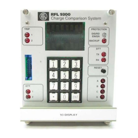
Page 127: Figure 6-1. Controls And Indicators, Typical Three-Terminal Rfl 9300 Charge Comparison System
ALARM ALARM 1 2 3 ALARM ALARM TX/RX ALARM RESET 4 5 6 7 8 9 22 14 Figure 6-1. Controls and indicators, typical three-terminal RFL 9300 Charge Comparison System RFL 9300 RFL Electronics Inc. January 30, 2002 (973) 334-3100... -
Page 128: Table 6-1. Controls And Indicators, Typical Three-Terminal Rfl 9300 Charge Comparison System
(See Figure 6-2 and Table 6-2 for more information on keypad functions.) If the RFL 9300 is in the PROGRAM mode or READ mode and the keypad is not used for 15 minutes, the RFL 9300 will automatically return to STANDBY mode. -
Page 129: Figure 6-2. The Rfl 9300 Keypad
Function [1] through [9], [0] Used to enter the security codes required to enter or exit some RFL 9300 display modes. Also used to enter t parameter numbers listed in Tables 6-5 or 6-6 (as applicable). When not activated for numeric entry, these keys are used to scroll between option selections for each mode [8] and [0] parameter displayed on the bottom line of the display. -
Page 130: Table 6-3. Rfl 9300 Module, General Information
Table 6-3. RFL 9300 Module, General Information Module Model Assembly Module Module location Additional Description Number Number Position Numbers Information (See Figure 6-3) Display Module 93B DISPLAY 106320 (HORIZ) Front Section 9 106320-1 (VERT) Supervisor Controller 93B SV 106300-1 Front... -
Page 131: Figure 6-3. Rfl 9300 Module Position Numbers
DISPLAY POWER SUPPLY POSITION 20 (250V POWER SUPPLY EXPANSION CHASSIS) (SEE SECTION 23) FRONT VIEW OF RFL 9300 WITH FRONT PANEL TILTED DOWN POS 12 POS 13 POS 14 POS 15 POS 16 POS 17 POS 18 POS 19 RELAY I/O... - Page 132 (50 HZ or 60 HZ, Two-terminal, 1A or 5A, Single-pole or Three-pole tripping). Turn on the local RFL 9300 by placing the POWER switch on the power supply module to the ON (up) position, and observe the following: a.
- Page 133 The word ALARM will still be displayed at the top line of the display, and typically the numbers “16” , “34 or 35” and “46” will still appear on the bottom line. This is because the remote RFL 9300 still has power OFF, and its transmit address has not been programmed.
- Page 134 The RFL 9300’s at both the local and remote locations are communicating with each other and are in a normal quiescent condition. The system is now in a normal state, with the RFL 9300 units at both ends of the protected line up and run- ning.
- Page 135 6-4 of this section.) e. The local RFL 9300 will remain in this state as long as the remote 1 and remote 2 termi- nals are turned OFF, and as long as the local terminal, and remote 1 and remote 2 termi- nal addresses have not been programmed.
- Page 136 6-4 of this Section). n. The local RFL 9300 will remain in this state as long as the remote 1 and remote 2 termi- nals are turned OFF, and as long as the remote 1 and remote 2 terminal addresses have not been programmed.
- Page 137 Turn on the remote 1 RFL 9300 by placing the POWER switch on the power supply module to the ON (up) position, and observe the following: a. All three indicators on the front of the power supply will light, indicating that the power sup- ply is functioning normally.
- Page 138 6-4 of this section.) m. This completes the programming of the remote 1 transmit addresses. Turn on the remote 2 RFL 9300 by placing the POWER switch on the power supply module to the ON (up) position, and observe the following: a.
-
Page 139: Display Modes
All three RFL 9300’s are communicating with each other and are in a normal quiescent condition. The system is now in a normal state, with the RFL 9300 units at all three ends of the protected line up and run- ning. -
Page 140: Table 6-4. Alarm Codes For Two-Terminal And Three-Terminal Rfl 9300 Charge Comparison System
6.4.1 THE STANDBY MODE When the RFL 9300 is in the STANDBY mode, a pair of dots move across both lines of the display, from left to right if there is no alarm condition. If an alarm condition occurs, the word "ALARM" and one or more code num- bers will appear on the display. - Page 141 During the READ mode, over 100 different parameters can appear on the RFL 9300's display. Table 6-5 is a list of all RFL 9300 parameter codes and their definitions for two-terminal systems, and Table 6-6 is a list of all RFL 9300 parameter codes and their definitions for three-terminal systems.
- Page 142 Parameter #s 48 - 49 RFL 9300 terminals are installed with a hot standby communications channel, setting Parameter #48 to AUTO will allow the RFL 9300 to switch automatically between channels every 12 hours. If Parameter #48 is set to MAN, the hot standby communications channel will be selected by Parameter #49.
- Page 143 The parameter name ("R1 GD BS") will appear on the top line of the display, with the bias level listed on the bottom line. >> Text continues on page 6-25 << RFL 9300 RFL Electronics Inc. January 30, 2002 6-18...
-
Page 144: Table 6-5. Read Mode Parameters For Rfl 9300 Two-Terminal Charge Comparison Systems
Table 6-5. READ mode parameters for RFL 9300 Two-Terminal Charge Comparison Systems Display Definition Moving dots RFL 9300 is in STANDBY mode. Display controller parameter; not user-selectable. EXIT Exit to STANDBY mode. Display function; can be set to either ENABLE or DISABLE. (1) PngPng 1 Value of ping-pong (round-trip delay) for remote 1. - Page 145 Table 6-5 continued. READ mode parameters for RFL 9300 Two-Terminal Charge Comparison Systems ACT CHAN Selects channel for hot standby communications. Programmable; see table 6-9 for more information. G B4 TRP Enable/disable guard before trip. Programmable; see table 6-9 for more information.
-
Page 146: Table 6-6. Read Mode Parameters For Rfl 9300 Three-Terminal Charge Comparison Systems
Table 6-6. READ mode parameters for RFL 9300 Three-Terminal Charge Comparison Systems Display Definition Moving dots RFL 9300 is in STANDBY mode. Display controller parameter; not user-selectable. EXIT Exit to STANDBY mode. Display function; can be set to either ENABLE or DISABLE. (1) PngPng 1 Value of ping-pong (round-trip delay) for remote 1. - Page 147 Table 6-6 continued. READ mode parameters for RFL 9300 Three-Terminal Charge Comparison Systems CM ALM D Communications alarm delay. Programmable; see table 6-10 for more information. DEFAULT Re-program to factory default values. Programmable; see table 6-10 for more information. (4) BEEPER Enable/disable audible beeper.
- Page 148 Table 6-6 continued. READ mode parameters for RFL 9300 Three-Terminal Charge Comparison Systems R2 FD PH Remote 2 fault detector phase current. R2 FD GD Remote 2 fault detector ground current. R2 BCKUP Remote 2 backup functions. R2 PH OC Remote 2 phase overcurrent backup.
- Page 149 It is recommended that this pa- rameter remain enabled. Alarms may not be noticed if the display is in the READ or PROGRAM mode, or if the RFL 9300 is not be- ing manned and the user is depending on the beeper to indicate an alarm condition.
- Page 150 The word "ENABLE" will appear on the bottom line of the display. Press the [ENT] key. The RFL 9300 will return to the STANDBY mode, and the display will return to the mov- ing dot pattern. 6.4.3 THE STARTUP MODE The Startup Mode is used during field commissioning of the relays and requires a password for entry and exit.
-
Page 151: Table 6-7. Startup Mode Parameters For Rfl 9300 Two-Terminal Charge Comparison Systems
[ENT] key to return the RFL 9300 to the STANDBY mode. (The PROGRAM mode requires a security code before returning to the STANDBY mode). If the EXIT parameter is disabled, pressing the [ENT] key will direct the RFL 9300 to move to the parameter. - Page 152 [ENT] keys to enter the required security code. The RFL 9300 will go through a sequence similar to a front panel button reset that will last for about six sec- onds. All the lamps will illuminate for a few seconds. Then the RFL 9300 will return to the STANDBY mode, and the display will return to the moving dot pattern.
-
Page 153: Table 6-9. Programmable Parameters, Rfl 9300 Two-Terminal Charge Comparison System
Table 6-9. Programmable parameters, RFL 9300 Two-Terminal Charge Comparison System Display Definition Range Step Default PH BIAS Phase bias 1.0 to 8.0 A 0.5 A 8.0 A GND BIAS Ground bias 1.0 to 2.25 A 0.25 A 2.25 A BIAS CTL... -
Page 154: Table 6-10. Programmable Parameters, Rfl 9300 Three-Terminal Charge Comparison System
Table 6-10. Programmable parameters, RFL 9300 Three-Terminal Charge Comparison System Display Definition Range Step Default PH BIAS Phase bias 1.0 to 8.0 A 0.5 A 8.0 A GND BIAS Ground bias 1.0 to 2.25 A 0.25 A 2.25 A BIAS CTL... - Page 155 It is recommended that this parame- ter remain enabled. Alarms may not be noticed if the display is in the READ or PROGRAM mode, or if the RFL 9300 is not being manned and the user is depending on the beeper to indicate an alarm condition.
- Page 156 RFL 9300 will exit the PROGRAM mode. Press the [.], [2], [4],[8] and [ENT] keys to enter the required security code. The RFL 9300 will return to the STANDBY mode, and the display will return to the moving dot pattern. RFL 9300 RFL Electronics Inc.
-
Page 157: Accessing The Rfl 9300 From A Pc Or Terminal
6.5 ACCESSING THE RFL 9300 FROM A PC OR TERMINAL You can use the RS-232 connector on the rear of the RFL 9300 to access it from a dumb terminal or a personal computer equipped with a terminal emulator. Once connected, you can use APRIL (Asynchronous Program- ming and Remote Interrogation Language) to do any of the following: View a list of parameter settings. -
Page 158: Figure 6-5. Cable Connections Between Rfl 9300 And Pc Or Terminal Using Xon/Xoff Handshaking
In order to select the RFL 9300's baud rate and handshaking protocol, you must enter the programming mode using the keypad on the RFL 9300's display controller and change two of its parameter settings. To do this, use the following procedure: Press the [ENT] key three times. - Page 159 Two different protocol methods can be selected: "XON/XOFF" (the default setting) and "RTS/CTS." The RFL 9300 will always transmit an "XON" when activating the RS-232 port, and an "XOFF" when de-activating the port. This will occur about every 100 ms, with the port activated for about 68 ms of the 100-ms period.
-
Page 160: Figure 6-6. April Commands For Use With Rfl 9300 (For Two-Terminal And Three-Terminal Mode)
[ENTER] keys: 9300>H [ENTER] This tells the RFL 9300 to send a list of APRIL commands to your terminal. A typical APRIL command list ap- pears in Figure 6-6. RFL Electronics APRIL(t) Remote Communications, Version 2.1 (c) 1993, 1996... -
Page 161: Figure 6-7. Typical Alarm Display For Two-Terminal Mode
Format: 9300>A [ENTER] The "A" command tells the RFL 9300 to send a copy of the alarms display to your terminal. A typical alarm dis- play for two-terminal mode is shown in Figure 6-7. A typical alarm display for three-terminal mode is shown in Figure 6-8. -
Page 162: Figure 6-8. Typical Alarm Display For Three-Terminal Mode
3I0 controller. Local Alarm From Supervisor Module: Local Charge Comparison Trip (calcu- 031 - SV LCCT A lated without active fault detector) Phase A. RFL 9300 RFL Electronics Inc. January 30, 2002 6-37 (973) 334-3100... - Page 163 Phase 3I0 Controller general alarm: Fail bus test with 93B SV, bad communications 063 – 3I0 Cntrlr with 93B SV, excessive channel delay detected, or system clock out of spec. RFL 9300 RFL Electronics Inc. January 30, 2002 6-38...
-
Page 164: Figure 6-9. Typical Values Display For Two-Terminal Mode
Format: 9300>V [ENTER] The "V" command tells the RFL 9300 to send a copy of the most recently measured values to your terminal. A typical values display for modem communications is shown in Figure 6-9 for two-terminal mode, and in Figure 6-10 for three-terminal mode. - Page 165 1 ( two-terminal systems only). One-half the round-trip communications channel delay between remote 2 and 101 - R2 Ping Pong local relay as measured by remote 2. RFL 9300 RFL Electronics Inc. January 30, 2002 6-40...
-
Page 166: Figure 6-11. Typical Read Settings Menu For Two-Terminal Single-Pole Mode
6.5.5 READING PARAMETER SETTINGS The "D" command tells the RFL 9300 to send a list of all parameter settings to your terminal. This list of settings is called the "read settings" menu. Format: 9300>D [ENTER] Typical read settings menus appear in Figures 6-11 through 6-14. All settings described in Section 4 of this manual are shown, but you can't change the displayed values. -
Page 167: Figure 6-12. Typical Read Settings Menu For Two-Terminal Three-Pole Mode
Current Date 08/16/00 Current Time 09:27:06 Reset Disp. Alrm Single Pole Inactive Trip Release CS+TRIP System Label Gen1 9300> Figure 6-12. Typical read settings menu for two-terminal three-pole mode RFL 9300 RFL Electronics Inc. January 30, 2002 6-42 (973) 334-3100... -
Page 168: Figure 6-13. Typical Read Settings Menu For Three-Terminal Single-Pole Mode
2. If parameter No. 030 is disabled, then parameter numbers 031, 032 and 033 will display N/A (not applicable). 3. If parameter No. 034 is disabled, then parameter numbers 035, 036 and 037 will display N/A (not applicable). RFL 9300 RFL Electronics Inc. -
Page 169: Figure 6-15. Typical Configuration And Software Version Display For Two-Terminal And Three-Terminal Systems
The "F" command tells the RFL 9300 to send a configuration and software version display to your terminal. This display tells you how the RFL 9300 is configured, and what software version is being used in each of its control- lers (communications controller(s), supervisor controller, phase controllers, and display controller). -
Page 170: Figure 6-16. Typical Remote Parameters Display For A Two-Terminal Single-Pole System
Disable R1 PingPong 004.0 ms R1 CDC 004.0 ms R1 Single Pole Inactive R1 Trip Rls TRIP+100 9300> Figure 6-17. Typical Remote Parameters Display for a two-terminal three-pole system RFL 9300 RFL Electronics Inc. January 30, 2002 6-45 (973) 334-3100... -
Page 171: Figure 6-18. Typical Remote Parameters Display For A Three-Terminal Single-Pole System
R2 PingPong 004.0 ms R2 Single Pole Active R2 Slctv Pole RL Disable R2 Trip Rls TRIP+100 9300> Figure 6-18. Typical Remote Parameters Display for a three-terminal single-pole system RFL 9300 RFL Electronics Inc. January 30, 2002 6-46 (973) 334-3100... -
Page 172: Figure 6-19. Typical Remote Parameters Display For A Three-Terminal Three-Pole System
R2 Stub Bus Inactive R2 Guard/Trip Disable R2 PingPong R2 Single Pole Inactive R2 Trip Rls 019.5 ms 9300> Figure 6-19. Typical Remote Parameters Display for a three-terminal three-pole system RFL 9300 RFL Electronics Inc. January 30, 2002 6-47 (973) 334-3100... - Page 173 If parameter No. 063 is disabled, then parameter numbers 065 and 066 will display N/A (not applicable). If parameter No. 067 is disabled, then parameter numbers 069 and 070 will display N/A (not applicable). RFL 9300 RFL Electronics Inc. January 30, 2002...
- Page 174 31.875 amperes in 0.125 ampere steps. Remote 2 Phase Inverse Time-overcurrent Curve select. Refer to note 6 on 090 - R2 Ph TOC Curve page 6-28 for settings. RFL 9300 RFL Electronics Inc. January 30, 2002 6-49 (973) 334-3100...
- Page 175 If parameter No. 088 is disabled, then parameter numbers 090 and 091 will display N/A (not applicable). If parameter No. 092 is disabled, then parameter numbers 094 and 095 will display N/A (not applicable). RFL 9300 RFL Electronics Inc. January 30, 2002...
-
Page 176: Figure 6-20. Typical Update Screen For A Two-Terminal System
The displayed values are updated about once a second when operating at 2400 baud. This screen can be used to monitor RFL 9300 operation. To exit the update mode, press the [X] key, followed by the [ENTER] key. The screen on your terminal will be cleared, and the "9300>"... -
Page 177: Figure 6- 22. Sequence Of Events Menu
6.5.9 VIEWING THE SEQUENCE OF EVENTS LOGS The RFL 9300 maintains a list of the last five alarm events and the last five trip events that took place during system operation. The alarm events are stored in the “alarm sequence of events log” and the trip events are stored in the “trip sequence of events log”. -
Page 178: Figure 6-23. Typical Alarm Sequence Of Events Display
10:59:24 498 ms End of Last Alarm 06/07/95 10:59:28 906 ms Current Time 01/01/96 04:46:04 148 ms 9300-S> Figure 6-24. Typical alarm sequence of events display – page 2 RFL 9300 RFL Electronics Inc. January 30, 2002 6-53 (973) 334-3100... -
Page 179: Figure 6-25. Typical Trip Sequence Of Events Display
Figure 6-25. Typical trip sequence of events display – page 1 -001, -002, -069, +062, +027, -001, -002, -001, +058, -001, -098, -001, -001 -128, -065, -001, --Output Oscillography trip event 9300-S> Figure 6-26. Typical Oscillography data table RFL 9300 RFL Electronics Inc. January 30, 2002 6-54 (973) 334-3100... - Page 180 6.5.10 VIEWING OSCILLOGRAPHY DATA In addition to storing alarm and trip events, the RFL 9300 also stores oscillography data for the trip events, which can be viewed by the user. The stored oscillography data contains twelve cycles of all four measured trip currents which consist of six cycles of pre-trip data and six cycles of post trip data.
-
Page 181: Figure 6-27. A Typical Oscillography Data Plot
Phase A Phase B Phase C A trip B trip C trip 3IO trip Milliseconds Figure 6-27. A typical oscillography data plot RFL 9300 RFL Electronics Inc. January 30, 2002 6-56 (973) 334-3100... -
Page 182: Figure 6-28. Typical Programming Menu
You can use APRIL and your terminal to program the RFL 9300. All programming functions that are normally done using the keypad on the RFL 9300's display module can be done using a terminal. To use your PC or terminal to program the RFL 9300, use the "P" command. -
Page 183: Figure 6-29. Typical Parameter Settings List For A Three-Terminal System
To view a list of all current parameter settings, use the "D" command. Format: 9300-P>D [ENTER] When you enter the "D" command, the RFL 9300 sends a list of all current parameter settings to your terminal. A typical parameter settings list for a three-terminal system is shown in Figure 6-29. - Page 184 The RESET DISP. ALRM parameter is usually set to "NO." This is the reset for the display controller alarm and LED signal. It is the same as pressing the RESET switch on the front of the display control- ler. To reset the RFL 9300 using your terminal, type in the following: 9300-P> 122 [ENTER] The Reset Disp.
- Page 185 The "SV" command saves any new settings you made while in the programming mode: Format: 9300-P>SV [ENTER] The "SV" command tells the RFL 9300 to store all the changes in its non-volatile RAM memory. Once the changes are stored, the "9300-P>" prompt will re-appear.
-
Page 186: Rfl 9300 Addressing
When the "9300>" prompt is displayed, simply disconnect your PC or terminal from the RFL 9300's RS-232 connector. If you accessed the RFL 9300 through an RFL 9660 Digital Switch, type in the deselect code (nor- mally "BYE") to deselect the port, and then enter the "Q" command to terminate the session. (Refer to the RFL 9660 Instruction Manual for more information.) -
Page 187: Figure 6-31. A Typical Two-Terminal Installation Where Addressing Is Not Required
RFL 9300 transmit addresses are user selectable from “0016” to “4079” and are set to different values at the local and remote units. The sum of the local and remote addresses must equal 4095. For example, if the local address is set to “4000” then the remote address must be set to “0095”. The address programmed at the local unit is transmitted to the remote unit for address verification. -
Page 188: Figure 6-32. Typical Rfl 9300 Three-Terminal Addressing Scheme
4055 STATION A STATION B 0040 0050 4025 0070 LOCAL 4045 STATION C LOCATION OF OPERATOR C. View from station C. Figure 6-32. Typical RFL 9300 three-terminal addressing scheme RFL 9300 RFL Electronics Inc. January 30, 2002 6-63 (973) 334-3100... -
Page 189: Description Of Instantaneous Overcurrent Backup Trip Algorithm And Inverse Time Overcurrent Backup Trip Algorithm
This allows the user to enable either the ground or phase time overcurrent functions separately or use them in conjunction with each other with the same or different pickup values, dial settings and curves. RFL 9300 RFL Electronics Inc. January 30, 2002... - Page 190 The time dial settings available for the IEC curves are: 0.05, 0.1, 0.2 , 0.3, 0.4, 0.5, 0.6, 0.7, 0.8, 0.9 and 1.0 . Note that the reset function for this trip algorithm is instantaneous. The reset time is not programmable by the operator. RFL 9300 RFL Electronics Inc. January 30, 2002...
- Page 191 TOC timer will instantaneously reset to 0 (reset function). If the fault current continues to be detected until the time recorded by the TOC timer exceeds the delay time stored in the delay timer, a trip signal will be issued. RFL 9300 RFL Electronics Inc. January 30, 2002...
-
Page 192: Time-Overcurrent Curve Equations
6.8 TIME-OVERCURRENT CURVE EQUATIONS Both US and IEC time-overcurrent curves are provided in the RFL 9300 relay. Use the PROGRAM mode to select the curve characteristics you desire. These time curve equations are valid for all time-overcurrent ele- ments. Plots showing operating time versus multiples of pickup current are shown on the following pages. The... - Page 193 Curve IEC3: Extremely Inverse - See Figure 6-39 = TD [ 80.0/(M - 1) ] Curve IEC4: Long Time Backup - See Figure 6-40 = TD [ 120.0/(M - 1) ] RFL 9300 RFL Electronics Inc. January 30, 2002 6-68 (973) 334-3100...
- Page 194 3 00 2 00 15 (12.5) 1 00 6 (5) 0 50 0.01 Time in Cycles Multiples of Pickup 60 Hz (50 Hz) Figure 6-33. Time Curve USA 1 RFL 9300 RFL Electronics Inc. January 30, 2002 6-69 (973) 334-3100...
- Page 195 2 00 15 (12.5) 1 00 6 (5) 0 50 3 (2.5) 0.01 Time in Cycles Multiples of Pickup 60 Hz (50 Hz) Figure 6-34. Time Curve USA 2 RFL 9300 RFL Electronics Inc. January 30, 2002 6-70 (973) 334-3100...
- Page 196 15 (12.5) 2 00 6 (5) 1 00 0 50 3 (2.5) 0.01 Multiples of Pickup Time in Cycles 60 Hz (50 Hz) Figure 6-35. Time Curve USA 3 RFL 9300 RFL Electronics Inc. January 30, 2002 6-71 (973) 334-3100...
- Page 197 3 00 6 (5) 2 00 3 (2.5) 1 00 0 50 0.01 Time in Cycles Multiples of Pickup 60 Hz (50 Hz) Figure 6-36. Time Curve USA 4 RFL 9300 RFL Electronics Inc. January 30, 2002 6-72 (973) 334-3100...
- Page 198 0.30 30 (25) 0.20 15 (12.5) 0.10 0.05 6 (5) 3 (2.5) 0.01 Time in Cycles 60 Hz (50 Hz) Multiples of Pickup Figure 6-37. Time Curve IEC 1 RFL 9300 RFL Electronics Inc. January 30, 2002 6-73 (973) 334-3100...
- Page 199 15 (12.5) 0.50 0.40 0.30 0.20 6 (5) 3 (2.5) 0.10 0.05 0.01 Time in Cycles 60 Hz (50 Hz) Multiples of Pickup Figure 6-38. Time Curve IEC 2 RFL 9300 RFL Electronics Inc. January 30, 2002 6-74 (973) 334-3100...
- Page 200 0.90 0.80 0.70 3 (2.5) 0.60 0.50 0.40 0.30 0.20 0.10 0.05 0.01 Time in Cycles 60 Hz (50 Hz) Multiples of Pickup Figure 6-39. Time Curve IEC 3 RFL 9300 RFL Electronics Inc. January 30, 2002 6-75 (973) 334-3100...
- Page 201 150 (125) 0.60 0.50 0.40 0.30 60 (50) 0.20 30 (25) 0.10 0.05 Time in Cycles 60 Hz (50 Hz) Multiples of Pickup Figure 6-40. Time Curve IEC 4 RFL 9300 RFL Electronics Inc. January 30, 2002 6-76 (973) 334-3100...
-
Page 202: Section 7: Laboratory Acceptance Tests
This section contains procedures for testing two 9300 relays that are connected back-to-back. It is also possi- ble to perform some tests on a single RFL 9300 that is communicating with itself (its transmitter connected to its receiver). These single-relay tests will be described in Section 8 of this manual. -
Page 203: System Setup
Using the READ display mode, verify that the delay in the communications link is normal. The PINGPONG value should read about 18 ms for modem versions, or 4 ms for direct digital or fiber versions. >> text continues on page 7-4 << RFL 9300 RFL Electronics Inc. October 20, 2004 7 - 2... -
Page 204: Figure 7-1. Back-To-Back Relay, Test Setups
Back-to-back test setup using modems +5Vdc RS-449 RS-449 Cable Cable Assembly Assembly Direct Direct RFL DCE Digital Digital RFL 9300 Emulator 9300 Interface Interface (105880) Module Module b. Back-to-back test setup using direct digital interfaces Fiber Fiber Fiber Optic I/O... -
Page 205: Test Procedures
PROGRAM mode to change them. NOTE The RFL 9300 relay determines breaker open/closed status on the basis of AC line current meas- urements. If all four Phase Controller’s measure peak AC line current <= 1/8A for 40ms the su- pervisor will issue the open breaker signal. - Page 206 Ground delay. 7.4.1 ALARM CONDITIONS AND TRANSMIT ADDRESS ALARM Verify the RFL 9300's local alarm output by removing the phase A controller module. The red SYS indicator on the 93B SV LED will light. The display will read "ALARM 60 34"...
- Page 207 At the present time the local RFL 9300 transmit address is set to “4000” and the remote RFL 9300 transmit address is set to “0095”. These addresses are compatible since their sum equals 4095.
- Page 208 7.4.2 DIRECT TRANSFER TRIP At one RFL 9300, connect a dc circuit with 0.2-ampere loading in series with the DTT-1 trip circuit (rear- panel terminals TB2-1 and TB2-2). This will be the receiving RFL 9300 during this procedure. At the other RFL 9300, connect a dc voltage across the DTT-IN terminals (rear-panel terminals TB9-3 and TB9-4) as follows: If the Alarm I/O is strapped for 48Vdc, connect a 38Vdc to 58Vdc voltage source.
-
Page 209: Figure 7-2. Test Connections Simulating An External A-G Fault
Figure 7-2. Test connections simulating an external A-G fault Vary the magnitude of the ac test current. Place either RFL 9300 in the READ display mode, and ver- ify that the Phase A and 3I 0 currents are the same value as the test current. - Page 210 The display ac current readings and settings are in terms of rms amperes. However, the RFL 9300 does not measure current. Instead, it measures "charge," or the area under the half-cycle current wave. For display purposes, the RFL 9300 converts charge to ac rms current (assuming a perfect, symmetrical, 60-Hz sine wave).
-
Page 211: Figure 7-3. Test Connections Simulating An External A-B Fault
RIGHT TERMINAL CURRENT SOURCE Figure 7-3. Test connections simulating an external A-B fault LEFT TERMINAL RIGHT TERMINAL CURRENT SOURCE Figure 7-4. Test connections simulating an external three-phase fault RFL 9300 RFL Electronics Inc. October 20, 2004 7 - 10 (973) 334-3100... -
Page 212: Figure 7-5. Phasor Diagram, Single-Phase Test Simulation Of An External Three-Phase Fault
IB, IC IB, IC Figure 7-5. Phasor diagram, single-phase test simulation of an external three-phase fault LEFT RELAY RIGHT RELAY Figure 7-6. Phasor diagram, real external three-phase fault RFL 9300 RFL Electronics Inc. October 20, 2004 7 - 11 (973) 334-3100... -
Page 213: Figure 7-7. Test Connections Simulating An Internal A-G Fault
The current polarities at the left terminal and the right terminal are the same. This cre- ates an "internal" current line-up for Phase A and ground. LEFT TERMINAL RIGHT TERMINAL CURRENT SOURCE Figure 7-7. Test connections simulating an internal A-G fault RFL 9300 RFL Electronics Inc. October 20, 2004 7 - 12 (973) 334-3100... - Page 214 At 1.5 amperes, several actions will occur: The red SYS indicator on the 93B SV module will light. The red ALARM indicator on the 93B PC module monitoring Phase A will light. RFL 9300 RFL Electronics Inc. October 20, 2004...
- Page 215 5 ms faster than the times at lower currents. In general, trip times should be 11 to 25 ms for fiber or direct digital versions of the RFL 9300, and 25 to 40 ms for the modem version.
-
Page 216: Figure 7-8. Test Connections Simulating An Internal A-B Fault
The red FD indicators on the 93B PC modules monitoring Phase A and Phase B will light. 5 (optional). Measure trip times for various current levels. The results should be roughly the same as for A-G faults. RFL 9300 RFL Electronics Inc. October 20, 2004 7 - 15 (973) 334-3100... -
Page 217: Figure 7-9. Test Connections Simulating An Internal Three-Phase Fault
The other phase-to-ground (B-G and C-G) and phase-to-phase (B-C and C-A) internal faults may be simulated by modifying the test circuit connections shown in Figures 7-7 and 7-8 to energize the other phases. RFL 9300 RFL Electronics Inc. October 20, 2004... -
Page 218: Figure 7-10. Test Connections Simulating An Internal A-G Fault With Weak Infeed At The Right Terminal
7.4.9 WEAK-FEED INTERNAL A-G FAULTS The RFL 9300's Weak-Feed Trip ("WFT") logic is activated when it senses a small current at one terminal and a large current at the other terminal. This condition is an internal fault with weak infeed at one terminal. The RFL 9300 defines "small"... - Page 219 All red FD indicators on the 93B PC module will flash momentarily, allowing the RFL 9300 at the left terminal to trip on the received WFT message. The RFL 9300 at the left terminal then sends "Charge Comparison Trip - Ultimate" (CCT-U) signals to the right RFL 9300, causing it to trip.
-
Page 220: Figure 7-11. Test Connections Simulating An Internal A-G Fault With Breaker Open At The Right Terminal
In 2-terminal mode the RFL 9300 will transmit a Weak Current Message (WCM) whenever the local breaker is open (no AC line current >1/8 A peak detected for 40 ms by all phase controllers). When an RFL 9300 re- ceives a WCM, it will allow tripping if the local current is greater than the bias setting. A single fault detector, on the phase in question, satisfies the fault detector requirement for the 3I0 controller. - Page 221 If two synchronized ac current sources are available, with the phase angle between test currents adjustable, tests may be done to demonstrate the "rainbow" characteristic, "Delay Measurement Based On Load" (DML) and "outfeed." These optional tests are described in the next three procedures. RFL 9300 RFL Electronics Inc. October 20, 2004...
-
Page 222: Figure 7-12. Test Connections For Oscillography Test
Windows HyperTerminal emulator. This procedure is described in Section 6 under the heading “ACCESSING THE RFL 9300 FROM A PC OR TERMINAL”. Establish communication between the RFL 9300 and your PC or laptop. When communication has been established the RFL 9300 will send the following prompt to your PC: 9300>... -
Page 223: Figure 7-13. Oscillography Test Data Plot
Type “O” [ENTER] to download the oscillography record from the RFL 9300 oscillography board to the PC or laptop. Click on “TRANSFERS”. Click on “CAPTURE TEXT”. Enter a new filename using the following format: XXXX.TXT. For example you can name the file OSC1.TXT. -
Page 224: Section 8: Field Commissioning
This will force the relay to reinitiate, and establish a new channel delay compen- sation value. It is also recommended at this time, that all relay settings be reconfirmed, and recorded as the “As Left Condition”. RFL 9300 RFL Electronics Inc. October 20, 2004... -
Page 225: Introduction
8.1 INTRODUCTION This section contains the procedures required to put a two-terminal RFL 9300 system into service in the field. These include the following: Description Of Tests Paragraph Single-Relay Tests (Optional procedure) Verification Of End-To-End Communications Startup Mode Final Commissioning It is assumed that the mounting and wiring procedures described in Section 5 of this manual have been per- formed, and the relays are in place. - Page 226 A dc voltage source capable of supplying either 48 Vdc or 125 Vdc, depending upon the power supplies installed in the RFL 9300. A dc current source that can provide at least 0.4 amperes to drive two 0.2A dc sense circuits.
-
Page 227: Figure 8-1. Single Relay Test Setups
Fiber d. Single relay test setup using SHFI To Station Battery G.703 9300 Module e. Single relay test setup using G.703 Figure 8-1. Single relay test setups RFL 9300 RFL Electronics Inc. October 20, 2004 8 - 4 (973) 334-3100... - Page 228 6.1 of this manual. Set up the system relay parameters in accordance with paragraph 7.3. Perform all steps in each test procedure in the order shown, unless otherwise directed. Expected results and/or comments are indented and appear in boldface type. RFL 9300 RFL Electronics Inc. October 20, 2004 8 - 5...
- Page 229 J5 jumper back to the “normal” position before placing the 9300 into service. Place the power switch on the RFL 9300's power supply in the on ("1") position. Set the Trans- mit Address of the unit to “0000”.
- Page 230 Place the RFL 9300 back in the STANDBY display mode. The display will return to the moving dot pattern. If you plan on using a dumb terminal to access the RFL 9300 through its RS-232 port, refer to paragraph 6.5 in Section 6 of this manual.
-
Page 231: Table 8-1. Programmable Parameters, Rfl 9300 Two-Terminal Charge Comparison System
Table 8-1. Programmable parameters, RFL 9300 Two-Terminal Charge Comparison System Display Definition Setting PH BIAS Phase bias 3.0 A GND BIAS Ground bias 1.5A BIAS CTL Bias control ENABLE * GND DLY Ground delay DISABLE DLAY SEC Bias control and ground delay time... -
Page 232: Table 8-2. Programmable Parameters, Rfl 9300 Three-Terminal Charge Comparison System
It is recommended that this parame- ter remain enabled. Alarms may not be noticed if the display is in the READ or PROGRAM mode, or if the RFL 9300 is not being manned and the user is depending on the beeper to indicate an alarm condition. - Page 233 The following procedure tests the RFL 9300's local alarm, and communications alarm functions. Verify the RFL 9300's local alarm output by removing the phase A controller module. The red SYS indicator on the 93B SV LED will light. The display will read "ALARM 60 34"...
- Page 234 When testing an RFL 9300 equipped with a modem module, both wires in the twisted pair must be disconnected. If one wire is left connected, a longer recov- ery time may be required to restore communications. This is because disconnect- ing a single wire interrupts the communications path in both directions, but inter- wire coupling keeps a small signal present in both directions.
-
Page 235: Figure 8-2. Test Connections Simulating An Internal A-G Fault
Connect the equipment as shown in Figure 8-2. This creates an "internal" current line-up for Phase A and ground. CURRENT SOURCE Figure 8-2. Test connections simulating an internal A-G fault RFL 9300 RFL Electronics Inc. October 20, 2004 8 - 12 (973) 334-3100... - Page 236 The red SYS indicator on the 93B SV module will light. The red alarm indicator on the 93B Phase A Controller module will light. The message "ALARM 34 31 61" will appear on the display. RFL 9300 RFL Electronics Inc. October 20, 2004...
- Page 237 A/D converter failure. If you leave this condition on, you will note that the alarm disappears every few seconds and then comes back. This shows that the RFL 9300 is trying to clear the alarm. Simulate an actual fault by applying the LCCT current level suddenly.
-
Page 238: Figure 8-3. Test Connections Simulating An Internal A-B Fault
The red FD indicators on the 93B PC modules monitoring Phase A and Phase B will light. 5 (optional). Measure trip times for various current levels. The results should be roughly the same as for A-G faults. RFL 9300 RFL Electronics Inc. October 20, 2004 8 - 15 (973) 334-3100... -
Page 239: Figure 8-4. Test Connections Simulating An Internal Three-Phase Fault
Results should be similar to the results obtained for the A-B fault simulation, ex- cept all three phase targets (A, B, and C) should now operate. The reclose block output (terminals TB9-1 and TB9-2) also should operate. RFL 9300 RFL Electronics Inc. October 20, 2004... - Page 240 Return the overcurrent backup settings to the default values (31.87 amperes phase and 31 am- peres ground). The single-relay tests are now complete. To return the RFL 9300 to normal operation, proceed as follows: Make sure the power switch on the RFL 9300's power supply is in the off ("0") position.
-
Page 241: Verification Of End-To-End Communications
Five different procedures are provided for verifying end-to-end communications: one for modem versions of the RFL 9300, one for direct digital versions, one for fiber optic versions, one for short haul fiber versions, and one for G.703 versions. Use the proper procedure for your RFL 9300:... - Page 242 The proper jumper settings will depend on the DCE being connected to the RFL 9300. Try to use the RFL 9300 with J2 and J3 in Position B. If the SEND timing is not working properly, move J2 to Position A. If the RECEIVE timing is not working properly, move J3 to Position A.
-
Page 243: Table 8-3. Acceptable Received Fiber Optic Power Levels, Rfl 9300 Charge Comparison System
The transmit fiber should be connected to the TX bulkhead connector on the 93 FT/FR I/O module at the rear of the RFL 9300. The receive fiber should be connected to the RX bulkhead connector on the 93 FT/FR I/O module. - Page 244 The following procedure verifies end-to-end communications for RFL 9300 relays equipped with short haul fiber modules. No additional equipment is required to perform this procedure. Make sure the connections between the RFL 9300 and the (FSU) fiber service unit have been properly made.
-
Page 245: Startup Mode
Differential Current test as well as the possibility that one station is phase inverted with respect to the other(s). RFL 9300 RFL Electronics Inc. October 20, 2004... - Page 246 [ENT] key is pressed when the selected value is displayed on the bottom line of the display. For more information on the RFL 9300's display modes, refer to the following paragraphs in this manual: STANDBY para. 6.4.1 READ para.
- Page 247 The message "SEC CODE" will appear on the display. This means that you must enter a security code before the RFL 9300 will enter the STARTUP Mode. Press the [.], [1], [3],[5] and [ENT] keys as the required security code.
-
Page 248: Table 8-4. Startup Mode Parameters For Rfl 9300 Two-Terminal Charge Comparison Systems
Table 8-4. STARTUP mode parameters for RFL 9300 Two-Terminal Charge Comparison Systems Display Definition Moving dots RFL 9300 is in STANDBY mode. Display controller parameter; not user-selectable. EXIT Exit to STANDBY mode. Display function; can be set to either ENABLE or DISABLE. - Page 249 The user should now remove the shunt from PHASE A current. NOTE ALL THREE UNITS IN A THREE TERMINAL SYSTEM SHOULD PASS THE PHASE SEQUENCE TEST BEFORE CONTINUING TO THE NEXT STEP IN THE COMMISSIONING PROCEDURE RFL 9300 RFL Electronics Inc. October 20, 2004 8 - 26...
-
Page 250: Figure 8-5. Electrical Connections Between Rfl 9300 And Current Transformers On Protected Line
PHASE B PHASE C (GROUND) Note that the test switch connections are not typical FT-1 test switch connections Figure 8-5. Electrical connections between RFL 9300 and current transformers on protected line (shows current test switches) RFL 9300 RFL Electronics Inc. - Page 251 One reason that the phase sequence test would fail at this point in the procedure is that a pair of inputs has been swapped. RFL 9300 RFL Electronics Inc. October 20, 2004...
- Page 252 IT IS POSSIBLE FOR A NON-ZERO VALUE OF DIFFERENTIAL CURRENT TO BE VALID IF THERE IS A TAPPED LOAD IN THE SYSTEM AND THE DIFFERENTIAL CURRENT IS EQUAL TO THE CURRENT IN THE TAP. RFL 9300 RFL Electronics Inc. October 20, 2004...
- Page 253 Be sure that there are no tapped loads in the system affecting the test. NOTE BRINGING A RELAY ON LINE WITHOUT CORRECTING A FAILED DIFFERENTIAL CURRENT TEST WILL CAUSE THE RELAY TO MISOPERATE. RFL 9300 RFL Electronics Inc. October 20, 2004 8 - 30...
-
Page 254: Figure 8-6. Correctly Wired Two-Terminal System
1 relay, and the differential current on Phase A will be zero. This can be seen in Figure 8- Station A Station B 2 Amps 2 Am RFL 9300 RFL 9300 Communications Channel Terminal Terminal... -
Page 255: Figure 8-8. Phase Inversion At Local Relay
If there is a phase inversion at the local relay, the resulting differential current indicated at both stations will be approximately double the current, or about four amps. This can be seen in Figure 8-8. Station A Station B 2 Amps 2 Amps RFL 9300 RFL 9300 Communications Channel Terminal Terminal Phase input to... -
Page 256: Figure 8-9. Correctly Wired Three-Terminal System
1 relay as shown in Figure 8-9, and the differential current on Phase A will be zero. Station A Station B 5 Amps 2 Amps RFL 9300 RFL 9300 Three Three Terminal Terminal... - Page 257 Current that will be displayed at all stations will be approximately double the current at remote 2, or about 6 amps. Station A Station B 5 Amps 2 Amps RFL 9300 RFL 9300 Three Three Terminal Terminal Remote 1...
- Page 258 Current that will be displayed at all stations will be approximately double the current at remote 1 or about 10 amps. Station A Station B 2 Amps 5 Amps Phase input to remote 1 relay RFL 9300 RFL 9300 inverted Three Three Terminal Terminal Remote 1...
-
Page 259: Figure 8-12. Phase Inversion At Local Station
Current that will be displayed at all stations will be approximately double the current at the local station or about 4 amps. Station A Station B 5 Amps 2 Amps Phase input RFL 9300 RFL 9300 to local relay Three Three inverted Terminal... - Page 260 008 - Local 3I0 Remote #1 Phase A current. 009 - Remote #1 I A Remote #2 Phase A current. (3 terminal only) 013 - Remote #2 I A RFL 9300 RFL Electronics Inc. October 20, 2004 8 - 37 (973) 334-3100...
-
Page 261: Final Commissioning
[ENT] keys to enter the required security code. The RFL 9300 will go through a sequence similar to a front panel button reset that will last for about six sec- onds. All the lamps will illuminate for a few seconds. Then the RFL 9300 will return to the STANDBY mode and the display will return to the moving dot pattern. -
Page 262: Section 9: Display Module
Figure 9-1. RFL 9300 display module for horizontal chassis 9.1 INTRODUCTION The RFL 9300 display module (93B DISPLAY), shown in Figure 9-1, serves as the user interface to the RFL 9300. Entries on its keyboard place the RFL 9300 into one of its four operating modes. Programmable parame- ters can be set by keyboard entries while the RFL 9300 is in the PROGRAM mode. -
Page 263: Table 9-1. Rfl 93B Display Module, General Information
DS304 DTT RX - Front-panel indicator; lights red when a DTT signal is received from the remote terminal. DS305 BACKUP - Front-panel indicator; lights red when the RFL 9300 goes into the back-up mode. This will happen when Parameter 20 (BACKUP) has been enabled, and a communications failure oc- curs. -
Page 264: Figure 9-2. Controls And Indicators For Display Controller Board, Used In Rfl 9300 Display Module
DS302B DS302A TP302 TP303 Figure 9-2. Controls and indicators for display controller board, used in RFL 9300 display module CONNECTORS When the RS-232 front panel interface board (106755) is installed, a cable from the board P302 plugs into P302 of the display controller board. When the RS-232 front panel interface board (106755) is not installed, programmable jumpers (P/N 98306) are used to jump pins 4 &... - Page 265 U323, which will also reset the receive flag signal from the oscillography card by placing a reset signal on pin A26. The receive process will continue if more than one byte of data was requested. RFL 9300 RFL Electronics Inc.
- Page 266 The Display Controller works hand-in-hand with the Supervisor Controller to both initialize and monitor the interface between the RFL 9300 relay and the Single-Pole chassis. The Supervisor will test SP_DETECT. If this line is low it indicates that the single-pole chassis is present in the system. In that case, the generic Single-Pole chassis alarm (Alarm #54) will become active and the alarm message will be transmitted to the Display Controller.
-
Page 267: Oscillography Board
Those described as front-panel controls are accessible with the RFL 93B DISPLAY installed in the RFL 9300 chassis; all others are only accessible when the RFL 93B DISPLAY is removed from the chassis, or is placed on card extenders. -
Page 268: Figure 9-3. Controls And Indicators For Oscillography Board, Used In Rfl 93B Display Module
RESET switch SW302 on the display controller board. TEST TURRETS Ground reference TP101 IRIG-B test point TP102 IRIG-B test point TP103 ACTEL probe test point TP104 ACTEL probe test point TP105 RFL 9300 RFL Electronics Inc. August 9, 2001 9 - 7 (973) 334-3100... - Page 269 J103 are in the “in” position, this circuit strips off the carrier and leaves a digital representation of the IRIG-B signal. If the jumpers are in the “out” position, the signal is passed to the processor without demodulation. This is used when an unmodulated signal is supplied to the RFL 9300. TRIP SIGNALS Optoisolators, U101-U105 are used to electrically isolate the trip and DTT input signals from the logic circuits.
-
Page 270: Front Panel
If the keypad column is made low but no key is pressed, the KEY0 through KEY3 lines will all be high. The microcontroller continuously scans all the columns on the keypad look- ing for pressed keys. RFL 9300 RFL Electronics Inc. August 9, 2001... - Page 271 Table 9-2. Replaceable parts for display controller board, used in RFL 9300 display module. (Assembly No. 106325-2) Circuit Symbol Description Part Number (Figs. 9-4 & 9-7) CAPACITORS C301-324, 329 Capacitor, ceramic, 0.01μF, GMV, 50V 1007 1366 C325, 326 Capacitor, ceramic, 22pF, 5%, 200V...
- Page 272 Table 9-2 continued. Replaceable parts for display controller board, used in RFL 9300 display module Circuit Symbol Description Part Number (Figs. 9-4 & 9-7) SEMICONDUCTORS - continued. U311 IC, MOS, Nonvolatile timekeeping RAM 0615 437 U312, 313 IC, MOS, Octal, tri-state latch...
-
Page 273: Figure 9-4. Component Locator Drawing For Display Controller Board, Used In Rfl 9300 Display Module
Figure 9-4. Component locator drawing for display controller board, used in RFL 9300 display module (Assembly No. 106325-2) RFL 9300 RFL Electronics Inc. August 9, 2001 9 - 12 (973) 334-3100... -
Page 274: Description
Table 9-3. Replaceable parts for oscillography board, used in RFL 9300 display modules (Assembly No. 106330) Circuit Symbol Description Part Number (Figs. 9-5 & 9-7) CAPACITORS C101 Capacitor, tantalum, 33μF, 10%, 10V 1007 1142 C102, 103 Capacitor, electrolytic, 47μF, 20%, 25V... -
Page 275: Description
Table 9-3 continued. Replaceable parts for oscillography board, used in RFL 9300 display module Circuit Symbol Description Part Number (Figs. 9-5 & 9-7) RESISTORS (continued) RZ101, 102 Resistor network, 10K, 5R/PKG, SIP 32664 RZ103 99117 Resistor network, 220Ω, 5R/PKG, SIP... -
Page 276: Figure 9-5. Component Locator Drawing For Oscillography Board, Used In Rfl 9300 Display Module
Figure 9-5. Component locator drawing for oscillography board, used in RFL 9300 display module (Assembly No. 106330) RFL 9300 RFL Electronics Inc. August 9, 2001 9 - 15 (973) 334-3100... -
Page 277: Description
Table 9-4. Replaceable parts for front panel assembly, used in RFL 9300 display module (Assembly No. 106335) Circuit Symbol Description Part Number (Figs. 9-6 & 9-7) CAPACITORS C201-205 0130 51041 Capacitor, ceramic, 0.1μF, 10%, 50V C206-208 1007 1142 Capacitor, tantalum, 33μF, 10%, 10V... -
Page 278: Figure 9-6. Component Locator Drawing For Front Panel Assembly, Used In Rfl 9300 Display Module
Figure 9-6. Component locator drawing for front panel assembly, used in RFL 9300 display module (Assembly No. 106335) RFL 9300 RFL Electronics Inc. August 9, 2001 9 - 17 (973) 334-3100... -
Page 279: Figure 9-7. Oscillography Board, Part Of Rfl 9300 Display Module (Assembly No. 106330; Schematic No. D-106764-A)
Figure 9-7. Oscillography Board, part of RFL 9300 display module (Assembly No. 106330; Schematic No. D- 106764-A) Sheets 1 of 5 through 5 of 5 Please see Figure 9-7, Sheets 1 of 5 through 5 of 5, in Section 32: Schematics RFL 9300 RFL Electronics Inc. -
Page 280: Figure 10-1. Rfl 9300 Supervisor Controller Module
Those described as front-panel controls are accessible with the RFL 93B DISPLAY in- stalled in the RFL 9300 chassis; all others are only accessible when the RFL 93B SV is removed from the chas- sis, or is on a card extender. -
Page 281: Figure 10-2. Controls And Indicators, Rfl 9300 Supervisor Controller Module
DS 1 2000 RFL ELECTRONICS, BOONTON, NJ USA ECB 93B SUPERVISOR CONTROL NO. 106303-1 REV A Figure 10-2. Controls and indicators, RFL 9300 supervisor controller module CONFIGURATION JUMPERS Selects operating frequency: Position A for 60 Hz, Position B for 50 Hz. - Page 282 10.3 THEORY OF OPERATION The RFL 93 SV Supervisor Controller Module serves as the communications hub of the RFL 9300. It also per- forms the following tasks: It generates the system clock, which is the "heartbeat" of all RFL 9300 activity.
- Page 283 SUPER_RD interrupt signal will be issued to the Supervisor Controller. The Su- pervisor Controller will respond by once again setting SUPR/W high, isolating the external controller modules from the mailbox memory. RFL 9300 RFL Electronics Inc. October 29, 2001...
- Page 284 RS-485 transceiver located on the display controller board. The DC RDY signal is supplied by the display controller. If this signal is a logic one, the display controller is not ready to communicate with the RFL 93B SV. RFL 9300 RFL Electronics Inc. October 29, 2001...
- Page 285 CHASSIS ALARM locally (#54) and transmit the alarm message to the Display Controller. If the Single-Pole chassis is connected to the RFL 9300 but jumper J5 is in the H position, the Single-Pole chassis is said to be in three-pole mode. In this mode none of the single-pole trip algorithms apply and the RFL 9300 operates as a normal two-terminal or three-terminal relay with six additional output trip contacts per phase.
- Page 286 3I0 Trip Algorithm - When the RFL 9300 relay is configured for single-pole operation the GROUND DELAY func- tion takes on an additional role. If GROUND DELAY is not enabled, trips calculated by the 3I0 controller will have no effect. In certain applications, such as tapped loads, the ground bias may be set much more sensitive than the phase bias and only a 3I0 trip signal will be available to clear low-level internal faults.
- Page 287 DC RDY (U1-4) This is a serial communications handshake control signal. received from the display controller (Section 9). Its function was described in paragraph 10.3.4 of this manual. RFL 9300 RFL Electronics Inc. October 29, 2001 10 - 8...
- Page 288 This signal is also received from the Alarm I/O module. It reflects the status of the Direct Transfer Trip signal at the local station. A logic zero indicates an active DTT signal. The Supervisor Controller sends this signal to the remote RFL 9300 through the Communications Controller. RECLOSE (U1-7) This is an active-low logic signal sent to the Alarm I/O module.
- Page 289 Table 10-1. Replaceable parts, supervisor controller module for RFL 9300 RFL 93B SV (Assembly No. 106300-1) Circuit Symbol Description Part Number (Figs. 10-3 & 10-4) CAPACITORS C1-7,9-20,23-30,35,39,40 0120 38 Capacitor,ceramic dip,0.1μF,10%,50V C31,32,43 1007 1645 Capacitor,ceramic dip,0.01μF,5%,100V,AVX SR301A103JAA or equiv. 0125 22205...
- Page 290 Table 10-1 continued. Replaceable parts, supervisor controller module for RFL 9300 Charge Comparison System Circuit Symbol Description Part Number (Figs. 10-3 & 10-4) SEMICONDUCTORS DS1,2 Light-emitting diode,red,right-angle PC mount, extended length, Industrial 99294 Devices 5300H1 or equiv. U1,3 MOS octal buffer/driver,20-pin DIP, Motorola MC74ACT244N or equiv.
-
Page 291: Figure 10-3. Component Locator Drawing, Supervisor Controller Modules For Rfl 9300
Figure 10-3. Component locator drawing, supervisor controller modules for RFL 9300 (Assembly No. 106300-1; Drawing No. D-106300-1-A) RFL 9300 RFL Electronics Inc. October 29, 2001 10 - 12 (973) 334-3100... -
Page 292: Figure 10-4. Supervisor Controller Module For Rfl 9300 Charge Comparison System
Figure 10-4. Supervisor Controller module for RFL 9300 Charge Comparison System(Assembly No. 106300; Sche- matic No. D-106304-1-B) Sheets 1 of 2 and 2 of 2 Please see Figure 10-4, Sheets 1 of 2 and 2 of 2, in Section 32: Schematics RFL 9300 RFL Electronics Inc. -
Page 293: Figure 11-1. Rfl 93B Act I/O Auxiliary Current Transformer I/O Module
I/O Module. These controls and indicators are described below. Only the rear-panel terminal block (TBX) is accessible with the RFL 93B ACT I/O installed in the RFL 9300 chassis; all others are only accessible when the RFL 93B ACT I/O is either removed from the chassis, or placed on a card extender. -
Page 294: Figure 11-2. Controls And Indicators, Rfl 93B Act I/O Auxiliary Current Transformer I/O Module
The RFL 93B ACT I/O contains a current transformer, a sense amplifier with high-current buffer, an analog switch, a current-to-voltage converter with high-current buffer, and a buffered 200-Hz low-pass filter. A block diagram of the RFL 93B ACT I/O appears in Figure 11-3. RFL 9300 RFL Electronics Inc. March 26, 1999... -
Page 295: Figure 11-3. Block Diagram, Rfl 93B Act I/O Auxiliary Current Transformer I/O Module
POWER UP RESET is held high, keeping the output of the sense amplifier disconnected from T1's feedback winding. This is done for 650 ms, and provides a smooth power-up sequence for the RFL 93B ACT I/O. RFL 9300 RFL Electronics Inc. March 26, 1999... -
Page 296: Table 11-1. Replaceable Parts, Rfl 93B Act-5 5-Ampere Auxiliary Current Transformer To I/O Module
0410 1384 Resistor,metal film,100K,1%,1/4W, Type RN1/4 0410 1480 Resistor,metal film,301K,1%,1/4W, Type RN1/4 0410 1526 R25,26 Resistor,metal film,4.99K,1%,1/4W, Type RN1/4 0410 1355 Resistor,metal film,113K,1%,1/4W, Type RN1/4 0410 1485 RFL 9300 RFL Electronics Inc. March 26, 1999 11 - 4 (973) 334-3100... - Page 297 TL081IP or equiv. MOS quad analog switch,SPST,ON resistance 100W maximum @ 0605 17 +85 o C,16-pin DIP, Siliconix DG441DJ or equiv. MISCELLANEOUS COMPONENTS Transformer, current drive 100541 RFL 9300 RFL Electronics Inc. March 26, 1999 11 - 5 (973) 334-3100...
-
Page 298: Figure 11-4. Component Locator Drawing, Rfl 93B Act-5 5-Ampere Auxiliary Current Transformer I/O Module
Figure 11-4. Component locator drawing, RFL 93B ACT-5 5-Ampere Auxiliary Current Transformer I/O Module (Assembly No. 106345-5; Drawing No. C-106345, Rev. A) RFL 9300 RFL Electronics Inc. March 26, 1999 11 - 6 (973) 334-3100... -
Page 299: Figure 11-5. Rfl 93B Act-5 5-Ampere Auxiliary Current Transformer I/O Module (Assembly No. 106345; Schematic No. D-105814, Rev. C)
Figure 11-5. RFL 93B ACT-5 5-Ampere Auxiliary Current Transformer I/O Module (Assembly No. 106345; Sche- matic No. D-105814, Rev. C) Please see Figure 11- 5 in Section 32: Schematics RFL 9300 RFL Electronics Inc. March 26, 1999 11 - 7... - Page 300 This page intentionally left blank RFL 9300 RFL Electronics Inc. March 26, 1999 11-8 (973) 334-3100...
-
Page 301: Figure 12-1. Rfl 9300 Phase Controller Module
These controls and indicators are described below. Those described as front-panel controls are accessible with the RFL 93B PC installed in the RFL 9300 chassis; all others are accessible when the RFL 93B PC is removed from the chassis, or is placed on a card extender. -
Page 302: Figure 12-2. Controls And Indicators, Rfl 9300 Phase Controller Modules
DS 2 TP 7 TP 8 Figure 12-2. Controls and indicators, RFL 9300 phase controller modules JUMPERS Set at the factory according to the type of device installed for U14 and U15. Position A is used for 27C256 devices, and Position B is used for 27C64 or 27C128 devices. Do not change the setting of this jumper, unless U14 and U15 are being replaced with another device type. - Page 303 Monitoring point for 5-volt reference voltage. 12.3 THEORY OF OPERATION The RFL 9300's protection algorithms are executed by U9, a 16-bit microcontroller. Timers inside U9 are pro- grammed to monitor the system clock signal supplied by the Supervisor Controller through edge connector ter- minal P1-C11.
- Page 304 This backup function has the capability of operating even if the Supervisor Controller can't communi- cate with the phase controller modules. U20 also supplies the ACT gain range switch signals mentioned above. RFL 9300 RFL Electronics Inc. March 26, 1999...
-
Page 305: Table 12-1. Replaceable Parts, Phase Controller Modules For Rfl 9300 Charge Comparison System
9). This current signal gives the trip signal good immunity against noise transients as the opto-coupler has a slow turn-on time. Table 12-1. Replaceable parts, phase controller modules for RFL 9300 Charge Comparison System RFL 93B PC (Assembly No. 106370) - Page 306 Table 12-1 continued. Replaceable parts, phase controller modules for RFL 9300 Charge Comparison System Circuit Symbol Description Part Number (Figs. 12-3 & 12-4) RESISTORS - continued. R24,25 Resistor,metal film,221W,1%,1/4W, Type RN1/4 0410 1225 Resistor,metal film,100W,1%,1/4W, Type RN1/4 0410 1192 RZ1-6 Resistor network,nine 10KW 2% resistors,1.25W total,10-pin SIP,Bourns 4310R-101-103 or equiv.
-
Page 307: Figure 12-3. Component Locator Drawing, Phase Controller Modules For Rfl 9300 Charge Comparison System
Figure 12-3. Component locator drawing, phase controller modules for RFL 9300 Charge Comparison System (Assembly No. 106370) RFL 9300 RFL Electronics Inc. March 26, 1999 12 - 7 (973) 334-3100... -
Page 308: Figure 12-4. Phase Controller Modules For Rfl 9300 Charge Comparison System
Figure 12-4. Phase Controller modules for RFL 9300 Charge Comparison System (Assembly No. 106370; Sche- matic No. D-103819, Rev. D) Sheets 1 of 2 an 2 of 2 Please see Figure 12-4, Sheets 1 of 2 and 2 of 2, in Section 32: Schematics RFL 9300 RFL Electronics Inc. -
Page 309: Figure 13-1. Rfl 9300 Communications Controller Module
Module. These controls and indicators are described below. Those described as front-panel controls are acces- sible with the RFL 93B CC installed in the RFL 9300 chassis; all others are only accessible when the RFL 93B CC is removed from the chassis, or is on a card extender. -
Page 310: Figure 13-2. Controls And Indicators, Rfl 9300 Communications Controller Module
TP 3 TP 2 TP 6 TP 5 Figure 13-2. Controls and indicators, RFL 9300 communications controller module LED INDICATORS P-P - Front-panel indicator; lights green when a ping-pong test (round-trip delay measurement) is in progress. BER OK - Front-panel indicator; lights green when the bit error rate (BER) is within limits. - Page 311 The microprocessor compresses the message with the highest priority and loads it into the transmitter shift reg- isters, along with CRC bits. The RFL 93B CC module at the remote RFL 9300 will use the CRC bits to test the message when it receives it.
-
Page 312: Figure 13-3. Block Diagram, Rfl 9300 Communications Controller Module
Figure 13-3. Block diagram, RFL 9300 communications controller module RFL 9300 RFL Electronics Inc. February 7, 2000 13 - 4 (973) 334-3100... - Page 313 OPERATION If the RFL 9300 contains an RFL 93 DD Direct Digital I/O Module or an RFL 93 FT/FR module, the RFL 93B CC module learns the communication configuration based on the clock rate received and the strap settings passed over from the RFL 93B SV.
- Page 314 U18-38, where an interrupt occurs on the low-to-high transition. U18 reads the data latched in U7 and tests U18-17 (P2.1) to see if the data is valid during the processing of the word. RFL 9300 RFL Electronics Inc. February 7, 2000...
-
Page 315: Figure 13-4. Transmitter Timing Diagram, Rfl 9300 Communications Controller Module
Figure 13-4. Transmitter timing diagram, RFL 9300 communications controller module RFL 9300 RFL Electronics Inc. February 7, 2000 13 - 7 (973) 334-3100... -
Page 316: Figure 13-5. Receiver Timing Diagram, Rfl 9300 Communications Controller Module
Figure 13-5. Receiver timing diagram, RFL 9300 communications controller module RFL 9300 RFL Electronics Inc. February 7, 2000 13 - 8 (973) 334-3100... - Page 317 U18, and latched outputs for the alarm and hot standby lines. U24's inputs are micro- controller address bus A15 through A8, and the /READ and /WRITE strobe lines. A logic diagram for U24 ap- pears in Figure 13-6. RFL 9300 RFL Electronics Inc. February 7, 2000...
-
Page 318: Figure 13-6. Logic Diagram For Programmable Logic Device U24
Figure 13-6. Logic diagram for programmable logic device U24 RFL 9300 RFL Electronics Inc. February 7, 2000 13 - 10 (973) 334-3100... -
Page 319: Table 13-1. Replaceable Parts, Communications Controller Modules For Rfl 9300 Charge Comparison System
/WR and /RD strobe line down for the slower peripheral logic devices, such as U14. Table 13-1. Replaceable parts, communications controller modules for RFL 9300 Charge Comparison System RFL 93B CC (Assembly No. 106365) Circuit Symbol... - Page 320 Table 13-1 continued. Replaceable parts, communications controller module for RFL 9300 Charge Comparison System Circuit Symbol Description Part Number (Figs. 13-7 & 13-8) SEMICONDUCTORS - continued. MOS hex inverter,14-pin DIP,National Semiconductor 0615 185 MM74HC04N or equiv. U13,14 MOS shift register,8-input w/input flip-flop,16-pin DIP,Motorola 0615 374 MC74HC597N or equiv.
-
Page 321: Figure 13-7. Component Locator Drawing, Communications Controller Module For Rfl 9300
Figure 13-7. Component locator drawing, communications controller module for RFL 9300 RFL 9300 RFL Electronics Inc. February 7, 2000 13 - 13 (973) 334-3100... -
Page 322: Figure 13-8. Communications Controller Modules For Rfl 9300 Charge Comparison System
Figure 13-8. Communications Controller modules for RFL 9300 Charge Comparison System (Assembly No. 106365; Schematic No. D-103824, Rev. A) Sheets 1 of 2 and 2 and 2 Please see Figure 13-8, Sheets 1 of 2 and 2 of 2, in Section 32: Schematics RFL 9300 RFL Electronics Inc. -
Page 323: Figure 14-1. Rfl 9300 Modem Module
Figure 14-2 shows the location of these controls and indicators; they are described below. None of the RFL 93B MO's controls and indicators are accessible with the module installed in the RFL 9300 chassis; they can only be accessed when the RFL 93B MO is removed from the chassis, or is on a card ex- tender. -
Page 324: Figure 14-2. Controls And Indicators, Rfl 9300 Modem Module
TP 3 TP 9 TP 5 TP 4 J2, J3 Figure 14-2. Controls and indicators, RFL 9300 modem module JUMPERS Controls attenuation between RFL LC I/O module and RFL 93B MO. Place in Position A for no attenuation, or Position B for 3 dB of attenuation. - Page 325 RFL 93B MO. When the RFL 9300 is initialized, the RFL 93B CC module uses the control bus to configure the RFL 93B MO for CCITT .29 operation at a 7.2-Kbps data rate. The RFL 93B MO uses a modulation scheme known as "QAM" (quad- rature amplitude modulation).
- Page 326 J2 position. If this resistor is moved to the J3 position, an /RD strobe is produced. Voltage Regulator Circuits. The power supply for the RFL 9300 system produces +15-volt outputs, and the mo- dem on the RFL 93B MO requires +12 Vdc. U10, R9, and R10 form an equivalent 3-volt precision Zener. The volt- age between the anode and the gate of shunt regulator U10 is set at 2.5 volts by U10's internal gap band refer-...
- Page 327 14.3.3 INITIALIZATION When the RFL 9300 is initialized, the RFL 93B CC module sends commands over the modem bus. These com- mands reset the RFL 93B MO and configure it for 7.2-Kbps operation. The RFL 93B MO must receive a "training sequence"...
-
Page 328: Table 14-1. Replaceable Parts, Modem Modules For Rfl 9300 Charge Comparison System
Table 14-1. Replaceable parts, modem modules for RFL 9300 Charge Comparison System RFL 93B MO (Assembly No. 106355) Circuit Symbol Description Part Number (Figs. 14-3 & 14-4) CAPACITORS C1-5,7-10,12,13,16-20 Capacitor,X7R ceramic,0.1μF,10%,50V,AVX SA305C104KAA or equiv. 0130 51041 Capacitor,tantalum,33μF,20%,10V,Kemet T322D336M010AS or equiv. - Page 329 Table 14-1 continued. Replaceable parts, modem modules for RFL 9300 Charge Comparison System Circuit Symbol Description Part Number (Figs. 14-3 & 14-4) SEMICONDUCTORS - continued. MOS quad 2-input NAND gate,14-pin DIP,National Semiconductor MM74HC00N or equiv. 0615 159 MOS 2-to-4 line decoder/demultiplexer,16-pin DIP,Signetics 74HC139N or equiv.
-
Page 330: Figure 14-3. Component Locator Drawing, Modem Module For Rfl 9300 Charge Comparison System
Figure 14-3. Component locator drawing, modem module for RFL 9300 Charge Comparison System RFL 9300 RFL Electronics Inc. May 1, 1998 14 - 8 (973) 334-3100... -
Page 331: Figure 14-4. Modem Module For Rfl 9300 Charge Comparison System
Figure 14-4. Modem module for RFL 9300 Charge Comparison System (Assembly No. 106355; Schematic No. D- 103829, Rev. B) Please see Figure 14-4 in Section 32: Schematics RFL 9300 RFL Electronics Inc. May 1, 1998 14 - 9 (973) 334-3100... - Page 332 This page intentionally left blank RFL 9300 RFL Electronics Inc. May 1, 1998 11-10 (973) 334-3100...
-
Page 333: Section 15: Line Coupler I/O Module
The RFL 93 LC I/O has no controls or indicators; it is a passive module. There is a four-position terminal block on its rear panel which provides connections to a four-wire telephone line: 4W TX Connect to terminals 1 and 2. 4W RX Connect to terminals 3 and 4. RFL 9300 RFL Electronics Inc. May 1, 1998 15 - 1... -
Page 334: Theory Of Operation
Isolation transformers T1 and T2 are specified for a high isolation voltage, so they block any common-mode volt- ages from reaching the inside of the RFL 9300. (Common-mode voltages are those where both inputs are high relative to ground.) If the potential applied to the inputs is differential, the voltage may appear on the secondary of the transformers and is limited by diodes CR1 through CR4. -
Page 335: Figure 15-2. Component Locator Drawing, Rfl 93 Lc I/O Line Couple I/O Module
P12,(P13) TB10 (TB11) Figure 15-2. Component locator drawing, RFL 93 LC I/O Line Couple I/O Module (Assembly No. 103835; Drawing No. C-103838, Rev. A) RFL 9300 RFL Electronics Inc. May 1, 1998 15 - 3 (973) 334-3100... -
Page 336: Figure 15-3. Rfl 93 Lc I/O Line Coupler I/O Module
Figure 15-3. RFL 93 LC I/O Line Coupler I/O Module (Assembly No. 103835; Schematic No. B-103839, Rev. B) RFL 9300 RFL Electronics Inc. May 1, 1998 15 - 4 (973) 334-3100... -
Page 337: Section 16: Direct Digital Interface I/O Module
The RFL 93 DD I/O Direct Digital Interface I/O Module (Fig. 16-1) allows digital communications equipment (DCE) to be connected directly to the RFL 9300. It serves as an interface between the RFL 9300's motherboard and a rear-panel connector that accepts RS-422 signals. The RFL 93 DD I/O acts only as a buffer, unless the system is configured for hot standby. -
Page 338: Figure 16-2. Controls And Indicators, Rfl 93 Dd Direct Digital I/O Module
B selects normal polarity. J2's setting will depend on the DCE being connected to the RFL 9300. Try to use the RFL 9300 with J2 in Position B; if the SEND timing is not working properly, move J2 to Position A. -
Page 339: Theory Of Operation
B selects normal polarity. J3's setting will depend on the DCE being connected to the RFL 9300. Try to use the RFL 9300 with J3 in Position B; if the RECEIVE timing is not working prop- erly, move J3 to Position A. -
Page 340: Table 16-1. Replaceable Parts, Rfl 93 Dd I/O Direct Digital Interface I/O Module
MOS quad 2-input NAND gate,14-pin DIP,National Semiconductor MM74HC00N or equiv. 0615 159 MOS quad 2-input multiplexer,16-pin DIP,National Semiconductor MM74HC157N or equiv. 0615 171 MOS quad 2-input Exclusive-OR gate,14-pin DIP,RCA CD74HCT86E or equiv. 0615 390 RFL 9300 RFL Electronics Inc. May 1, 1998 16 - 4 (973) 334-3100... -
Page 341: Figure 16-3. Component Locator Drawing, Rfl 93 Dd I/O Direct Digital I/O Module
Figure 16-3. Component locator drawing, RFL 93 DD I/O Direct Digital I/O Module (Assembly No. 103830-1; Drawing No. C-103833-1, Rev. A) RFL 9300 RFL Electronics Inc. May 1, 1998 16 - 5 (973) 334-3100... -
Page 342: Figure 16-4. Rfl 93 Dd I/O Direct Digital I/O Module (Assembly No. 103830-1; Schematic No. D-103834-1, Rev. A)
Figure 16-4. RFL 93 DD I/O Direct Digital I/O Module (Assembly No. 103830-1; Schematic No. D-103834-1, Rev. Please see Figure 16-4, in Section 32: Schematics RFL 9300 RFL Electronics Inc. May 1, 1998 16 - 6 (973) 334-3100... -
Page 343: Section 17: Single Width Fiber Optic Transceiver Module
The receiver section accepts inputs from a fiber optic I/O module (Section 18) and converts them back into RS- 422 signals that can be processed by the RFL 93B CC Communications Controller module (Section 13). RFL 9300 RFL Electronics Inc. -
Page 344: Description
The RFL 93B FT/FR single width fiber optic transceiver module is shown in Figure 17-1. The module occupies one dedicated module space in the front of the RFL 9300 chassis, and is used with a fiber optic I/O module that is located at the rear of the chassis. - Page 345 Relative Humidity: 95 percent, non-condensing. Dimensions: Width (including panel) 1.4 inches (3.6 cm) Height (including panel) 5 inches (12.7 cm) Depth (behind panel) 9 inches (22.9 cm) RFL 9300 RFL Electronics Inc. May 1, 1998 17 - 3 (973) 334-3100...
-
Page 346: Controls And Indicators
These controls and indicators are described below. Those described as front panel indica- tors are visible to the user with the RFL 93B FT/FR installed in the RFL 9300 chassis; all others are only acces- sible when the RFL 93B FT/FR is removed from the chassis or is on a card extender. -
Page 347: Figure 17-2. Controls And Indicators, Rfl 93B Ft/Fr Single Width Fiber Optic Transceiver Mode
TP 4 128K DIS1Q TP 2 DIS2Q TP 3 TP 1 TP 8 Figure 17-2. Controls and indicators, RFL 93B FT/FR single width fiber optic transceiver mode RFL 9300 RFL Electronics Inc. May 1, 1998 17 - 5 (973) 334-3100... -
Page 348: Theory Of Operation
FPGA, U10. A control signal for switching the fiber paths originates from CC#1 and signals are routed via the backplane. See Figure 17-4 for the signal routing diagram. RFL 9300 RFL Electronics Inc. May 1, 1998... -
Page 349: Figure 17-3. Block Diagram, Rfl 93B Ft/Fr Single Width Fiber Optic Transceiver Module
OUT OF ACTEL RX CARRIER LOCK DEMOD- ALARM DETECTOR ULATOR LINE RX_CLK DRIVER (RS422) Figure 17-3. Block diagram, RFL 93B FT/FR single width fiber optic transceiver module RFL 9300 RFL Electronics Inc. May 1, 1998 17 - 7 (973) 334-3100... -
Page 350: Figure 17-4. Rfl 9300 Fiber Optics Hot Standby Signal Routing Diagram
Figure 17-4. RFL 9300 Fiber Optics Hot Standby Signal Routing Diagram Please see Figure 17-4, in Section 32: Schematics RFL 9300 RFL Electronics Inc. May 1, 1998 17 - 8 (973) 334-3100... -
Page 351: Table 17-1. Replaceable Parts, Rfl 93B Ft/Fr Single Width Fiber Optic Transceiver Module
R25, 26 Resistor, metal film, precision, 499Ω, 1%, 1/4W 0410 1259 Resistor, metal film, precision, 47.5K, 1%, 1/4W 0410 1449 RZ1,2 Resistor network, 10K, 8R/PKG, SIP 95571 RFL 9300 RFL Electronics Inc. May 1, 1998 17 - 9 (973) 334-3100... - Page 352 Inductor, molded, RF, 100μH, 10% 103344 Bead, ferrite, shield 98457 Connector, JK male, 64 contact, DIN TP1-8 98441 3 Test point, terminal, orange 103347 Crystal, hybrid, clock oscillator, 3.584 MHz RFL 9300 RFL Electronics Inc. May 1, 1998 17 - 10 (973) 334-3100...
-
Page 353: Figure 17-5. Component Locator Drawing, Rfl 93B Ft/Fr Single Width Fiber Optic Transceiver Module
Figure 17-5. Component locator drawing, RFL 93B FT/FR single width fiber optic transceiver module (Assembly No. 106360) RFL 9300 RFL Electronics Inc. May 1, 1998 17 - 11 (973) 334-3100... -
Page 354: Figure 17-6. Rfl 93 Ft/Fr Singlewidth Fiber Optic Transceiver Module (Assembly No. 106360; Schematic No. D- 105849, Rev. B)
Figure 17-6. RFL 93 FT/FR Singlewidth Fiber Optic Transceiver Module (Assembly No. 106360; Schematic No. D- 105849, Rev. B) Please see Figure 17-6, in Section 32: Schematics RFL 9300 RFL Electronics Inc. May 1, 1998 17 - 12 (973) 334-3100... -
Page 355: Section 18: Single Width Fiber Optic I/O Module
SECTION 18: SINGLE WIDTH FIBER OPTIC I/O MODULE WARNING YOUR RFL 9300 TERMINAL MAY BE EQUIPPED WITH FIBER OPTIC INPUT/OUTPUT MODULES THAT HAVE FIBER OPTIC EMITTER HEADS. FIBER OPTIC EMITTER HEADS USE A LASER LIGHT SOURCE THAT PRODUCE INVISIBLE RADIATION. FIBER OPTIC COMMUNICATION SYSTEMS ARE INHERENTLY SAFE IN NORMAL OPERATION BECAUSE ALL RADIATION IS CONTAINED IN THE SYSTEM. -
Page 356: Introduction
A vari- ety of single width fiber optic I/O modules are available, allowing the RFL 9300 to be used with many different types of fiber optic cables. -
Page 357: Description
* Light levels are emitter outputs for fiber optic I/O modules, and detector inputs for fiber optic I/O modules. 18.3 SPECIFICATIONS As of the date this manual was published, the following specifications apply to all RFL 9300 single width fiber optic I/O modules, except where indicated. Because all RFL products undergo constant refinement and im- provement, these specifications are subject to change without notice. -
Page 358: Controls And Indicators
0.5nA, and 150mV is equivalent to about 3.0nA. Ground TP 2 TP 3 TP 5 TP 4 TP 1 Figure 18-2. Controls and indicators, RFL 93 FT/FR I/O-8M single width fiber optic I/O module RFL 9300 RFL Electronics Inc. January 19, 2005 18 - 4 (973) 334-3100... -
Page 359: Figure 18-3. Controls And Indicators, Rfl 93 Ft/Fr I/O-13S And 13 M Single Width Fiber Optic I/O Modules
Ground TP 2 TP 3 TP 4 TP 1 Figure 18-3. Controls and indicators, RFL 93 FT/FR I/O-13S and 13 M single width fiber optic I/O modules RFL 9300 RFL Electronics Inc. January 19, 2005 18 - 5 (973) 334-3100... -
Page 360: Figure 18-4. Controls And Indicators, Rfl 93 Ft/Fr I/O-13Sl And 15Sl Single Width Fiber Optic I/O Modules
TP 4 TP 5 TP 6 TP 2 TP 3 Figure 18-4. Controls and indicators, RFL 93 FT/FR I/O-13SL and 15SL single width fiber optic I/O modules RFL 9300 RFL Electronics Inc. January 19, 2005 18 - 6 (973) 334-3100... -
Page 361: Theory Of Operation
R9 produces a bias current which is essentially the same as the LED current. This causes the LED to emit, without modulation, a constant light output at approximately the average output power. RFL 9300 RFL Electronics Inc. January 19, 2005... - Page 362 A block diagram is shown in Figure 18-6, and a schematic diagram is shown in Figure 18-11. RFL 9300 RFL Electronics Inc. January 19, 2005...
-
Page 363: Figure 18-6. Block Diagram, Rfl 93 Ft/Fr-13M (Multimode) And Rfl 93 Ft/Fr-S (Singlemode) 1300-Nm Fiber Optic I/O Module
A window comparator is formed by dual comparator U3, whose open collector outputs are connected to pullup resistor R19 and the Tx alarm output. Resistors R16 and R18 provide hysterisis. The alarm output is an active low. RFL 9300 RFL Electronics Inc. January 19, 2005... - Page 364 A block diagram is shown in Figure 18-7 and a schematic diagram is shown in Figure 18-13. RFL 9300 RFL Electronics Inc. January 19, 2005...
-
Page 365: Figure 18-7. Block Diagram, Rfl 93 Ft/Fr 13Sl (1300-Nm Singlemode) And Rfl 93 Ft/Fr 15Sl (1550-Nm Singlemode)
R5, R6, R7 and R8. The open collector outputs of the comparators in U5 are connected to pull up resistor R4 and to the Tx alarm output on pin 2 of P2. The alarm output is active low. RFL 9300 RFL Electronics Inc. - Page 366 U13 and resistors R46 and R47. The output of this stage is the digital Rx Data signal. The other three sections of U13 are not used. RFL 9300 RFL Electronics Inc. January 19, 2005...
-
Page 367: Table 18-2. Replaceable Parts, Rfl 93 Ft/Fr I/O-8M Singlewidth Fiber Optic I/O Module
Resistor, metal film, precision, 4.32K, 1%, 1/4W 0410 1349 0410 2260 Resistor, metal film, precision, 511 Ω , 1%, 1/2W R23, 24, 25, 34 Resistor, metal film, precision, 499K, 1%, 1/4W 0410 1547 RFL 9300 RFL Electronics Inc. January 19, 2005 18 - 13 (973) 334-3100... - Page 368 Inductor, Molded, RF, 180 μ H, 10% L6, 7, 8 32505 1 Inductor, Molded, RF, 100 μ H, 10% Connector, plug, female, 64 contacts, DIN 99134 TP1-5 Test point, terminal, orange 98441 3 RFL 9300 RFL Electronics Inc. January 19, 2005 18 - 14 (973) 334-3100...
-
Page 369: Figure 18-8. Component Locator Drawing, Rfl 93 Ft/Fr I/O-8M 850-Nm Multimode Singlewidth Fiber Optic I/O Module (Assembly No. 105850; Drawing No. 105853-A)
C RFL ELECTRONICS INC BOONTON NJ U.S.A. Figure 18-8. Component locator drawing, RFL 93 FT/FR I/O-8M 850-nm Multimode Singlewidth Fiber Optic I/O Module (Assembly No. 105850; Drawing No. 105853-A) RFL 9300 RFL Electronics Inc. January 19, 2005 18 - 15... -
Page 370: Figure 18-9. Rfl 93 Ft/Fr Singlewidth Fiber Optic I/O Module -8M (Assembly No. 105850; Schematic No. D-105854, Rev. D)
Figure 18-9. RFL 93 FT/FR Singlewidth Fiber Optic I/O Module -8M (Assembly No. 105850; Schematic No. D- 105854, Rev. D) Please see Figure 18-9, in Section 32: Schematics RFL 9300 RFL Electronics Inc. January 19, 2005 18 - 16 (973) 334-3100... -
Page 371: Table 18-3. Replaceable Parts, Rfl 93 Ft/Fr I/O Singlewidth Fiber Optic I/O Modules
Resistor, metal film, precision, 182Ω, 1%, 1/4W 0410 1217 Resistor, metal film, precision, 133K, 1%, 1/4W 0410 1492 R27, 29 Resistor, metal film, precision, 110K, 1%, 1/4W 0410 1484 RFL 9300 RFL Electronics Inc. January 19, 2005 18 - 17 (973) 334-3100... - Page 372 Inductor, molded, 33 μH, 130MA L3, 4, 5, 6 32505 1 Inductor, molded, RF, 100 μH, 10% Connector, plug, female, 64 contact, DIN 99134 TP1-4 Test point, terminal, orange 98441 3 RFL 9300 RFL Electronics Inc. January 19, 2005 18 - 18 (973) 334-3100...
- Page 373 Figure 18-10. Component locator drawing, RFL 93 FT/FR I/O-13M and RFL 93 FT/FR I/O-13S RFL 9300 RFL Electronics Inc. January 19, 2005 18 - 19 (973) 334-3100...
-
Page 374: Figure 18-11. Rfl 93 Ft/Fr Singlewidth Fiber Optic I/O Modules, -13M (Assembly No. 105855; Schematic No. D- 105864, Rev. A), -13S (Assembly No. 105860; Schematic No. D-105864, Rev. A)
Figure 18-11. RFL 93 FT/FR Singlewidth Fiber Optic I/O Modules, -13M (Assembly No. 105855; Schematic No. D- 105864, Rev. A), -13S (Assembly No. 105860; Schematic No. D-105864, Rev. A) Please see Figure 18-11, in Section 32: Schematics RFL 9300 RFL Electronics Inc. January 19, 2005... -
Page 375: Table 18-4. Replaceable Parts, Singlewidth Fiber Optic I/O Modules
0410 1406 R28, 30 Resistor, metal film, precision, 24.9K, 1%, 1/4W 0410 1422 Resistor, metal film, precision, 182 Ω, 1%, 1/4W R29, 31, 40, 43 0410 1217 RFL 9300 RFL Electronics Inc. January 19, 2005 18 - 21 (973) 334-3100... - Page 376 Inductor, molded, 33 μH, 130 mA L3, 4, 5, 6 32505 1 Inductor, molded, 100 μH, 10% Connector, plug, female, 64 contacts, DIN 102061 TP2-6 Test point, terminal, orange 98441 3 RFL 9300 RFL Electronics Inc. January 19, 2005 18 - 22 (973) 334-3100...
-
Page 377: Figure 18-12. Component Locator Drawing, Rfl 93 Ft/Fr I/O-13Sl And Rfl 93 Ft/Fr I/O-15Sl
Figure 18-12. Component locator drawing, RFL 93 FT/FR I/O-13SL and RFL 93 FT/FR I/O-15SL RFL 9300 RFL Electronics Inc. January 19, 2005 18 - 23 (973) 334-3100... -
Page 378: Figure 18-13. Rfl 93 Ft/Fr Singlewidth Fiber Optic I/O Modules, -13Sl (Assembly No. 105865; Schematic No. D- 105869, Rev. A), -15Sl (Assembly No. 105870; Schematic No. D-105869, Rev. A)
Figure 18-13. RFL 93 FT/FR Singlewidth Fiber Optic I/O Modules, -13SL (Assembly No. 105865; Schematic No. D- 105869, Rev. A), -15SL (Assembly No. 105870; Schematic No. D-105869, Rev. A) Please see Figure 18-13, in Section 32: Schematics RFL 9300 RFL Electronics Inc. January 19, 2005... -
Page 379: Section 19: Power Supply Module
The wide range, 50 Watt power supply shown in Figure 19-1 is a multiple output, forward, dc to dc converter, which is used to supply regulated dc power to the RFL 9300 Charge Comparison System. The power supply operates from a 38 to 150 Vdc input and provides three regulated dc outputs: +5 Vdc at 2.5 Amps, + 15 Vdc at 1.3 Amps, and -15 Vdc at -0.6 Amps. -
Page 380: Specifications
19.2 SPECIFICATIONS As of the date this manual was published, the specifications shown in Table 19-1 apply to the RFL 9300 power supply module, except where indicated. Because RFL products undergo constant refinement and improvement, these specifications are subject to change without notice. -
Page 381: Theory Of Operation
S1 to the OFF position, and then plac- ing it back to the ON position. If it shuts down again, troubleshoot the RFL 9300's chassis to make sure that nothing external to the power supply is causing it to shut down. If nothing is found in the rest of the chassis and the power supply is still shutting down, the power supply may be defective, and should be serviced. -
Page 382: Table 19-2. Replaceable Parts, 50-Watt Power Supply Module For Rfl 9300 Charge Comparison System
Table 19-2. Replaceable parts, 50-watt power supply module for RFL 9300 Charge Comparison System RFL 48/125 Vdc (Assembly No. 106715-1) Circuit Symbol Description Part Number (Figs. 19-3 & 19-4) CAPACITORS C1, 2 Capacitor, film, polypropylene, 0.22μF, 20%, 275V 1007 1808 C3, 4 Capacitor, ceramic disc, 0.01μF... - Page 383 Table 19-2 continued. Replaceable parts, 50-watt power supply module for RFL 9300 Charge Comparison System Circuit Symbol Description Part Number (Figs. 19-3 & 19-4) RESISTORS – continued. R113 Resistor, metal film, axial, 953Ω, 1%, 1/4W 0410 1286 R114 Resistor, metal film, variable, 100Ω, 10%, 3/4W...
-
Page 384: Figure 19-2. Component Locator Drawings, 50-Watt Power Supply Module
CR11 .015u 9300 PS 48/125 DC INPUT PCB ECB NO 106718 REV C 1999 RFL ELECTRONICS, BOONTON, NJ U.S.A. a. Input board U103 U102 R122 DS103 R131 C116 C115 C110 R126 C113 C111 TP102 DS101 R129 R120 R116 R127 TP103... -
Page 385: Figure 19-3. 9300 Ps 48/125 Dc Power Supply Module For Rfl 9300 Charge Comparison System
Figure 19-3. 9300 PS 48/125 DC power supply module for RFL 9300 Charge Comparison System, (Assembly No. 106715-1; Schematic No. 106719-E) Please see Figure 19-3, in Section 32: Schematics RFL 9300 RFL Electronics Inc. May 5, 2002 19 - 7... - Page 386 This page intentionally left blank RFL 9300 RFL Electronics Inc. May 5, 2002 19-8 (973) 334-3100...
-
Page 387: Section 20: Relay I/O Module
Relay I/O Module is removed from the chassis, or is placed on a card extender. The Current Sense board and the Relay Output board do not have controls and indicators and therefore are not included under this heading. RFL 9300 RFL Electronics Inc. May 5, 2002... -
Page 388: Figure 20-2. Rear Panel Connectors And Terminal Blocks, Rfl 93B Relay I/O Module
TB2-7 and TB2-8 CCS AUX-4 CCS Output Connections: TB2-1 and TB2-2 CCS TRIP-1 TB2-3 and TB2-4 CCS TRIP-2 TB2-5 and TB2-6 CCS AUX-1 TB2-7 and TB2-8 CCS AUX-2 RFL 9300 RFL Electronics Inc. May 5, 2002 20 - 2 (973) 334-3100... -
Page 389: Figure 20-3. Controls And Indicators, Power/Rf-232 Board For Rfl 93B Relay I/O Module
3.3UF P6KE 30CA CR111 3.3UF .1UF E101 C103 C112 R107 R106 TP101 101106 102840 Figure 20-3. Controls and indicators, power/RF-232 board for RFL 93B Relay I/O Module RFL 9300 RFL Electronics Inc. May 5, 2002 20 - 3 (973) 334-3100... - Page 390 Input fuses; See Table 20-2 for replacement part numbers. F1, F2 Monitoring point for RS-232 port +V supply. TP101 Monitoring point for RS-232 port -V supply. TP102 Ground reference. TP103 RFL 9300 RFL Electronics Inc. May 5, 2002 20 - 4 (973) 334-3100...
-
Page 391: Theory Of Operation
D-subminiature (DB-9) connector J3 for remote programming and monitoring, 20.3.1 POWER/RS-232 BOARD The power/RS-232 board provides connections for station battery input to the RFL 9300. It also provides a con- nector for an RS-232 port. The components on the power/RS-232 board have circuit reference numbers be- tween 101 and 199. - Page 392 P202 and P203. 20.3.2.1 TRIP ENABLE FUNCTION During power-up sequences and system test modes, the RFL 9300's trip outputs must be disabled. The TRIP RELAY ENABLE signal from the oscillography board in the display module controls this function. When this line is high, the outputs of U203 tri-state.
-
Page 393: Table 20-1. Replaceable Parts, Rfl 93B Relay I/O, Power/Rs-232 Board
Suppressor,transient,voltage,1.5KE200CA 30266 MISCELLANEOUS COMPONENTS F1,2 Fuse,10A,3AG,250V,normal-blow 44395 010 Connector, JK male,9P,RT angle 101106 L101,102 30285 Inductor,10 μ H,5%,1.5A max P101 Connector,plug,female,64 cont,DIN 99134 TP101,102,103 Test point,terminal,orange 98441 RFL 9300 RFL Electronics Inc. May 5, 2002 20 - 7 (973) 334-3100... -
Page 394: Figure 20-4. Component Locator Drawing, Rfl 93B Relay I/O Module, Power/Rs-232 Board
R109 3.3UF P6KE 30CA CR111 3.3UF .1UF E101 C103 C112 R107 R106 TP101 101106 102840 Figure 20-4. Component locator drawing, RFL 93B Relay I/O module, Power/RS-232 board RFL 9300 RFL Electronics Inc. May 5, 2002 20 - 8 (973) 334-3100... -
Page 395: Table 20-2. Replaceable Parts, Rfl 93 Relay I/O Module, Current Sense Board
MISCELLANEOUS COMPONENTS K201 Relay,SPDT,12V,PCB,sealed 101236 K203,204,205,206 Relay,SPDT,12VDC,37.5MA,SPCL 102860 Inductor,axial,47 μ H,15%,1.6A 105411 P201 Connector,plug,female,64cont,DIN 99134 P202 Connector, wafer assembly,12 CKT 42082 12 Connector, JK male,16P,vertical P203 30202 RFL 9300 RFL Electronics Inc. May 5, 2002 20 - 9 (973) 334-3100... -
Page 396: Figure 20-5. Component Locator Drawing, Rfl 93B Relay I/O Module, Current Sense Board
12VDC 12VDC R207 5.11K C203 .1UF C201 .1UF R205 5.11K P202 5.11K 42082-12 R201 Figure 20-5. Component locator drawing, RFL 93B Relay I/O module, Current Sense Board RFL 9300 RFL Electronics Inc. May 5, 2002 20 - 10 (973) 334-3100... -
Page 397: Table 20-3. Replaceable Parts, Rfl 93 Relay I/O Module, Relay Output Board
90223 K1,2,7,8 Relay, SPST, 12VDC, 37.5 MA 102860 K9,10,11,12 Realy, reed, SPST, 100V, 250MA 102859 Transformer, modem matching 95595 TB2,3 Block terminal, 8 terminal, 7/16 center 102839 RFL 9300 RFL Electronics Inc. May 5, 2002 20 - 11 (973) 334-3100... -
Page 398: Figure 20-6. Component Locator Drawing, Rfl 93B Relay I/O Module, Relay Output Board
43173-12 23.7 69.8 90223 23.7 69.8 SPST 100V 1N4003 SPST 12VDC 1.5KE 400CA Figure 20-6. Component locator drawing, RFL 93B Relay I/O module, Relay Output board RFL 9300 RFL Electronics Inc. May 5, 2002 20 - 12 (973) 334-3100... -
Page 399: Figure 20-7. Rfl 93B Relay I/O Module, Power/Rs-232 Board
Figure 20-7. RFL 93B RELAY I/O module, Power/RS-232 board (Assembly No. 106388-1; Schematic No. D- 106389, Rev. D) Sheets 1 of 3 through 3 of 3 Please see Figure 20-7, Sheets 1 of 3 through 3 of 3, in Section 32: Schematics RFL 9300 RFL Electronics Inc. May 5, 2002... - Page 400 This page intentionally left blank RFL 9300 RFL Electronics Inc. May 5, 2002 20-14 (973) 334-3100...
-
Page 401: Section 21. Alarm I/O Module
21.1 DESCRIPTION The RFL 93 Alarm I/O Module (Fig. 21-1) is an interface module mounted at the rear of all RFL 9300 units. It provides connections for DTT input, 89B disconnect switch input, reclose block output, and alarm relay outputs. -
Page 402: Figure 21-2. Controls And Indicators, Rfl 93 Alarm I/O Module
ALARM N.C. N.O. N.C. N.O. Figure 21-2. Controls and indicators, RFL 93 Alarm I/O Module RFL 9300 RFL Electronics Inc. May 5, 2002 21 - 2 (973) 334-3100... - Page 403 JUMPERS: J5 and J6 (104775-5, 104775-6 and 104775-7) Used to wet the contacts of circuits that activate the module inputs. These jumpers should not be inserted with station battery voltages in excess of 125 Volts. RFL 9300 RFL Electronics Inc. May 5, 2002...
-
Page 404: Theory Of Operation
Two alarm relays are also present in the 93 Alarm I/O. If the local alarm or the com alarm connections at P9 A5 or A4 go low, Q5 or Q6 is biased on. This turns on Q1 or Q2 which actives the alarm relay. RFL 9300 RFL Electronics Inc. -
Page 405: Table 21-1. Replaceable Parts, Rfl 93 Alarm I/O Module
K4, 5 Relay, SPDT, 12V, PCB, sealed 101236 Inductor, 10μH, 5%, 1.5A max 30285 L2-12 Inductor, 10μH, 5%, 1.5A max 102698 TB8, 9 Terminal block, 6 terminal 101233 RFL 9300 RFL Electronics Inc. May 5, 2002 21 - 5 (973) 334-3100... -
Page 406: Table 21-2. Replaceable Parts, Rfl 93 Alarm I/O Module
Rectifier, avalanch, 600V, 1A, 1N4005 26935 Suppressor, transient voltage, 1.5KE350CA 101722 CR9, CR11 Diode, Zener, 10V, 5%, 1W, 1N4740A 33342 CR10, 12 Diode, silicon, rectifier, 1Amp, 1N4003 30769 RFL 9300 RFL Electronics Inc. May 5, 2002 21 - 6 (973) 334-3100... - Page 407 K4, 5 Relay, SPDT, 12V, PCB, sealed 101236 Inductor, 10μH, 5%, 1.5A max 30285 L2-12 Inductor, 10μH, 5%, 1.5A max 102698 Terminal block, 6 terminal 101233 TB8, 9 RFL 9300 RFL Electronics Inc. May 5, 2002 21 - 7 (973) 334-3100...
-
Page 408: Figure 21-3. Component Locator Drawing, Rfl 93 Alarm I/O Module
Connector ECB Assy. Drawing No. C-103853 Panel ECB Assy. Drawing No. C-104718 Figure 21-3. Component locator drawing, RFL 93 Alarm I/O Module, Assembly No. 104775-5 RFL 9300 RFL Electronics Inc. May 5, 2002 21 - 8 (973) 334-3100... -
Page 409: Section 22. Short Haul Fiber Interface Module And Fiber Service Unit
SECTION 22. SHORT HAUL FIBER INTERFACE MODULE AND FIBER SERVICE UNIT WARNING YOUR RFL 9300 TERMINAL MAY BE EQUIPPED WITH FIBER OPTIC INPUT/OUTPUT MODULES THAT HAVE FIBER OPTIC EMITTER HEADS. FIBER OPTIC EMITTER HEADS USE A LASER LIGHT SOURCE THAT PRODUCE INVISIBLE RADIATION. -
Page 410: Introduction
To eliminate this problem the RFL SHF module provides immunity by using a fiber optic communication path between the RFL 9300 and the digital channel equipment. Refer to paragraph 22.2 for more information on the RFL 93 SHF short haul fiber module. -
Page 411: Short Haul Fiber Interface Module
Relative Humidity: 90 percent, non-condensing @ 40 Dimensions: Width (including panel) 1.4 inches (3.6 cm) Height (including panel) 5 inches (12.7 cm) Depth (behind panel) 4.7 inches (12.0 cm) RFL 9300 RFL Electronics Inc. October 20, 2004 22 - 3 (973) 334-3100... -
Page 412: Figure 22-2. Controls And Indicators, Rfl 93 Shfi Short Haul Fiber Interface Module
Indicates that the remote fiber receiver has failed and the remote transmitter is sending yellow code detected by the local fiber receive channel. Figure 22-2. Controls and indicators, RFL 93 SHFI short haul fiber interface module RFL 9300 RFL Electronics Inc. October 20, 2004 22 - 4... -
Page 413: Fiber Service Unit
X.21 as inputs and outputs on the non-fiber side of the connection. The FSU can be located up to 2km away from the RFL 9300. The RFL FSU Fiber Service Unit has a 15-pin or 37-pin male D-subminiature connector on its front panel de- pending on the application. -
Page 414: Table 22-2. Replaceable Parts, Rfl 93 Shfi Short Haul Fiber Interface Module
Resistor, thick film, 0.56Ω, 1%, 1/4W 700-20R56034 Resistor, thick film, 47.5Ω, 1%, 1/4W 700-2047R534 Resistor, thick film, 0Ω, 1%, 1/8W 700-15000034 Resistor network, 10K, 8R/PKG, SIP 95571 RFL 9300 RFL Electronics Inc. October 20, 2004 22 - 6 (973) 334-3100... - Page 415 Connector, plug, female, 64 contact, DIN 99134 Connector, header, single 7 CKT 32802-7 L1, 2 Inductor, molded, 22uH, 227mA, 10% 470-10103 Inductor, molded, 4.7uH 470-10104 TP3, 4 98441-3 Testpoint, terminal, orange RFL 9300 RFL Electronics Inc. October 20, 2004 22 - 7 (973) 334-3100...
-
Page 416: Figure 22-4. Component Locator Drawing, Rfl 93 Short Haul Fiber Interface Module (Assembly No. 107500)
TP10 TP13 TP11 TP12 9300 SHORT HAUL MODULE ADAPTER ECB NO 107503 REV-C RFL ELECTRONICS INC.,BOONTON,NJ,USA Figure 22-4. Component locator drawing, RFL 93 short haul fiber interface module (Assembly No. 107500) RFL 9300 RFL Electronics Inc. October 20, 2004 22 - 8... -
Page 417: Figure 22-5. Schematic, Rfl 93 Short Haul Fiber Module (3 Sheets) (Assembly No. 107500; Schematic No. D-107504-C)
Figure 22-5. Schematic, RFL 93 Short Haul Fiber Module (3 sheets) (Assembly No. 107500; Schematic No. D- 107504-C) Please see Figure 22- 5, in Section 32: Schematics RFL 9300 RFL Electronics Inc. October 20, 2004 22 - 9 (973) 334-3100... - Page 418 This page intentionally left blank RFL 9300 RFL Electronics Inc. October 20, 2004 22-10 (973) 334-3100...
-
Page 419: Section 23: G.703 Interface I/O Module
The jumpers, potentiometers, and test points can only be accessed when the RFL 93 G.703 is out of the chassis or is on a card extender. RFL 9300 RFL Electronics Inc. -
Page 420: Figure 23-2. Controls And Indicators, Rfl 93 G.703 Interface I/O Module
TP 3 .0022UF TP 1 LOOP NORM 1999 RFL ELECTRONICS INC BOONTON, NJ, U.S.A. 93-G703 ECB NO 106733 REV B Figure 23-2. Controls and indicators, RFL 93 G.703 Interface I/O Module REAR-PANEL CONNECTOR Rear-panel 93 G.703, DB15 connector. The following pins are supported, and all other pins are not connected: Pin No. -
Page 421: Theory Of Operation
Tx oscillator is the best choice since the DCE inter- face does not exist. A jumper on the 93 G.703 module allows the RX clock to be looped out of the TX port. RFL 9300 RFL Electronics Inc. -
Page 422: Figure 23-3. Setting J5 For Normal Or Loops Operation
This keeps the phase locked loop from locking an octave away from the correct signal. Changes in the clock rate from the receiver are slowly tracked and integrated. The resultant 128 kHz signal is again divided in the Actel to create the receiver clock, a 64 kHz pulse. RFL 9300 RFL Electronics Inc. February 7, 2000... - Page 423 32nd reference clock pulse. This results in a very limited pull range with very little average jitter. This means that at the most, one correction of 279 ns will be added or subtract once every 500,000 ns, or one part in 1,792. RFL 9300 RFL Electronics Inc. February 7, 2000...
-
Page 424: Table 23-1. Replaceable Parts, Rfl 93 G.703 Interface I/O Module
0410 1201 Resistor, metal film, axial, 49.9K, 1%, 1/4W 0410 1415 Resistor, metal film, axial, 100 Ω , 1%, 1/4W 0410 1192 Resistor network, 10K, 8R/PKG, SIP 95571 RFL 9300 RFL Electronics Inc. February 7, 2000 23 - 6 (973) 334-3100... - Page 425 Inductor, power line, 10 μ H 30063 Connector, plug, female, 64 contact, DIN 99134 T1,2 Transformer, 1:1 coupling 103343 TP1, 2, 3 Test point, terminal, orange 98441 3 RFL 9300 RFL Electronics Inc. February 7, 2000 23 - 7 (973) 334-3100...
-
Page 426: Figure 23-4. Component Locator Drawing, Rfl 93 G. 703 Interface I/O Module
LOOP NORM 1999 RFL ELECTRONICS INC BOONTON, NJ, U.S.A. 93-G703 ECB NO 106733 REV B Figure 23-4. Component locator drawing, RFL 93 G. 703 Interface I/O Module (Assembly No. 106730) RFL 9300 RFL Electronics Inc. February 7, 2000 23 - 8... -
Page 427: Figure 23-5. Schematic, Rfl 93 G.703 Module (Assembly No. 106730; Drawing No. D-106734-B)
Figure 23-5. Schematic, RFL 93 G.703 module (Assembly No. 106730; Drawing No. D-106734-B) Please see Figure 23- 5, in Section 32: Schematics RFL 9300 RFL Electronics Inc. February 7, 2000 23 - 9 (973) 334-3100... - Page 428 This page intentionally left blank RFL 9300 RFL Electronics Inc. February 7, 2000 23-10 (973) 334-3100...
-
Page 429: Section 24: Single Pole Chassis
Tripping, which allows phase A, B or C to trip independently of the other two phases. A front panel view of the RFL 9300 Single Pole Chassis is shown in Figure 24-1. A rear panel view of the RFL 9300 Single Pole Chassis is shown in Figure 24-3. -
Page 430: Figure 24-2. Typical Rfl 9300 Single Pole Chassis, Front Panel View Showing Led Indicators
DS11 DS12 Figure 24-2. Typical RFL 9300 Single Pole Chassis, front panel view showing LED indicators 24.2.1 LED INDICATORS (See note on page 24-7) All LEDs are latched targets except DS10, DS11 and DS12. All targets are cleared by pressing the RESET but- ton on the Display Controller. -
Page 431: Figure 24-3. Typical Rfl 9300 Single Pole Chassis, Rear Panel View
TRIP1 TRIP2 AUX1 PHASE A PHASE B PHASE C Figure 24-3. Typical RFL 9300 Single Pole Chassis, rear panel view 24.2.2 TERMINAL BLOCKS 24.2.2.1 PHASE A TERMINAL BLOCKS TB1A AUX2 Auxiliary contacts available to the user for phase A AUX3... - Page 432 TB3B TRIP1 Trip 1 relay contacts for phase C TRIP2 Trip 2 relay contacts for phase C AUX2 Auxiliary contacts available to the user for phase C RFL 9300 RFL Electronics Inc. August 25, 2000 24 - 4 (973) 334-3100...
- Page 433 Signal ground TP19 TRIP_DISABLE Trip disable command from RFL 9300. Logic high blocks tripping. TP20 DISP_DATA Serial data line from the RFL 9300 display module to the single pole chassis TP21 CLK_IN 3.584 mHz local oscillator clock TP22 DISP_CLK Clock burst from 9300 display module to single pole chassis...
-
Page 434: Theory Of Operation - Hardware
Volt supply without affecting the operate speed of the relays. A debounce delay is created in the Actel between the A_IN signal and the A_TR1 trip output signal. This delay is from .5 to 1 ms. This results in a total trip delay of less than 5 ms. RFL 9300 RFL Electronics Inc. August 25, 2000... - Page 435 The +15, -15 and +5 volt supplies are monitored by the trip disable circuitry. If any of the supplies are not pre- sent, trip is disabled since the relays do not have power to operate. RFL 9300 RFL Electronics Inc.
-
Page 436: Theory Of Operation - Software
The Display Controller works closely with the Supervisor Controller to initialize and monitor the interface be- tween the RFL 9300 relay and the Single-Pole chassis. The Supervisor will test SP_DETECT (JP1-25) to determine if the Single-Pole chassis is present in the system. -
Page 437: Figure 24-5. 16-Bit Status Messages Transmitted By The Single-Pole Logic To The Supervisor At 250Ms Intervals
CHASSIS ALARM locally and transmit the alarm message to the Display Controller. As long as this alarm re- mains active the Display Controller will transmit the initialization message with bit 7 = logic 0, at 750ms intervals. RFL 9300 RFL Electronics Inc. - Page 438 3-second LED test. After the LED test is completed, the remaining modules, except for the comms cards in the RFL 9300, will execute a 3-second LED test. If there are any active trip signals on the main chassis a “TRIP ACTIVE”...
- Page 439 Backup Mode Trip - If the RFL 9300 is configured for single-pole trip operation and the relay is operating in backup mode, any trip signal that is calculated locally will result in all three single-pole breakers being tripped and a reclose block signal being issued. This is the case regardless of the status of Selective Pole Relaying which does not apply when backup mode is active.
-
Page 440: Table 24-2. Replaceable Parts, Rfl 9300 Single Pole Chassis
Table 24-2. Replaceable parts, RFL 9300 single pole chassis Assembly No. 106710 Circuit Symbol Description Part Number (Figs. 24-4 & 24-5) CAPACITORS C1-3 Capacitor, electrolytic, 22μF, 100V 1007 1429 C4-13, 15-18, 21, 23-29, Capacitor, ceramic dip, 0.1μF, 10%, 50V 0120 38... -
Page 441: Figure 24-6. Component Locator Drawing, Rfl 9300 Single Pole Chassis, Main Circuit Board
Figure 24-6. Component locator drawing, RFL 9300 single pole chassis, main circuit board (Assembly No. 106710) RFL 9300 RFL Electronics Inc. August 25, 2000 24 - 13 (973) 334-3100... - Page 442 Figure 24-7. Schematic, 9300 Single Pole Chassis (Drawing No. D-106714-B) Sheet 1 of 2 Please see Figure 24-7, Sheets 1 of 2 and 2 of 2, in Section 32: Schematics. RFL 9300 RFL Electronics Inc. August 25, 2000 24 - 14...
-
Page 443: Table 24-3. Replaceable Parts, Rfl 9300 Single Pole Chassis, Rear Panel Assembly
Table 24-3. Replaceable parts, RFL 9300 single pole chassis, rear panel assembly (Assembly No. 106705) Circuit Symbol Description Part Number (Figs. 24-6 & 24-7) C1-36 Capacitor, ceramic disc, 0.005μF, 20%, 3kV 1007 1264 J2, 3, 4 Connector, female, 15 position, DIN41612... -
Page 444: Figure 24-8. Component Locator Drawing, Rfl 9300 Single Pole Chassis, Rear Panel
Figure 24-8. Component locator drawing, RFL 9300 single pole chassis, rear panel (Assembly No. 106705) RFL 9300 RFL Electronics Inc. August 25, 2000 24 - 16 (973) 334-3100... -
Page 445: Figure 24-9. Schematic, 9300 Single Pole Chassis, Rear Panel (Drawing No. D-106709-C)
Figure 24-9. Schematic, 9300 Single Pole Chassis, Rear Panel (Drawing No. D-106709-C) Please see Figure 24-9, in Section 32: Schematics RFL 9300 RFL Electronics Inc. August 25, 2000 24 - 17 (973) 334-3100... - Page 446 This page intentionally left blank RFL 9300 RFL Electronics Inc. August 25, 2000 24-18 (973) 334-3100...
-
Page 447: Section 25. Chassis And Front Panel Rs-232 Module
Figure 25-1. Typical RFL 9300 chassis 25.1 DESCRIPTION The RFL 9300 chassis shown in Figure 25-1 serves as a protective enclosure for all 9300 plug-in modules. It also houses the RFL 93 INTER Interconnect Motherboard and the front panel RS-232 interface module. The motherboard and the RS-232 module can be seen with more detail in Figures 25-3, and 25-5 respectively. -
Page 448: Figure 25-2. Block Diagram Of Rs-232 Front Board
25.2 FRONT PANEL RS-232 INTERFACE MODULE The RS-232 interface module provides the RFL 9300 with a front panel RS-232 port. There is also an RS-232 port on the rear panel of the 9300 chassis which is located on the Relay I/O module. This can be seen in Figure 20-1. -
Page 449: Table 25-1. Replaceable Parts, Rfl 93 Inter Interconnected Motherboard
Connector, JK female, 64 contact, DIN 101280 1 J2, 3, 10, 11 Connector, JK female, 64 contact, DIN 101281 1 Connector, male, 26 pin 102863 Resistor, metal film, zero-ohm,1/4-watt 1510 2217 RFL 9300 RFL Electronics Inc. May 5, 2002 25 - 3 (973) 334-3100... -
Page 450: Figure 25-3. Component Locator Drawing, Rfl 93 Inter Interconnect Motherboard
Figure 25-3. Component locator drawing, RFL 93 INTER Interconnect Motherboard (Assembly No. 103905-1; Drawing No. D-103908-1-C) RFL 9300 RFL Electronics Inc. May 5, 2002 25 - 4 (973) 334-3100... -
Page 451: Figure 25-4. Rfl 93 Inter Interconnect Motherboard (Assembly No. 103905-1; Schematic No. D-103909-1-D)
Figure 25-4. RFL 93 INTER Interconnect Motherboard (Assembly No. 103905-1; Schematic No. D-103909-1-D) Please see Figure 25- 4, in Section 32: Schematics. RFL 9300 RFL Electronics Inc. May 5, 2002 25 - 5 (973) 334-3100... -
Page 452: Figure 25-5. Component Locator Drawing, Rfl 9300 Front Panel Rs-232 Module
Table 25-2. Replaceable parts, RFL 9300 front panel RS-232 interface module Assembly No. 106755 Circuit Symbol Description Part Number (Figs. 25-5 & 25-6) C1, 2 Capacitor, ceramic, 0.1uF, 10%, 100V 151-10104050608 C3-5, 8-10 Capacitor, ceramic, 0.1uF, 10%, 50V 151-10104040603 C6, 7... -
Page 453: Figure 25-6. Rs-232 Front Panel Interface (Assembly No. 106755; Schematic No. C-106759-B)
Figure 25-6. RS-232 Front Panel Interface (Assembly No. 106755; Schematic No. C-106759-B) Please see Figure 25- 6, in Section 32: Schematics. RFL 9300 RFL Electronics Inc. May 5, 2002 25 - 7 (973) 334-3100... - Page 454 This page intentionally left blank RFL 9300 RFL Electronics Inc. May 5, 2002 25-8 (973) 334-3100...
-
Page 455: Section 26: Expansion Chassis
250VDC station battery power. The expansion chassis contains a power supply which converts 250VDC station battery power to 48VDC. The 48VDC is then used to power the RFL 9300 chassis via TB1 at the rear of the Re- lay I/O module (Section 20). The expansion chassis is an option which is only used in some RFL 9300 installa- tions. -
Page 456: Figure 26-2. Component Locator Drawing, Rfl 9300 Expansion Chassis Power Supply (Assembly No. 106350)
Inductor,10μH,5%,1.5A max Not applicable 101121 Terminal block,5 terminal,right angle 102843 Converter,DC-DC,48V,100W Not applicable Figure 26-2. Component locator drawing, RFL 9300 expansion chassis power supply (Assembly No. 106350) RFL 9300 RFL Electronics Inc. February 7, 2000 26 - 2 (973) 334-3100... -
Page 457: Figure 26-3. Schematic, Power Converter I/O - 250 Vdc, For Rfl 9300 Charge Comparison System
Figure 26-3. Schematic, Power Converter I/O – 250 Vdc, For RFL 9300 Charge Comparison System (Assembly No. 106350; Schematic, No. C-106354-B) Please see Figure 26- 3, in Section 32: Schematics RFL 9300 RFL Electronics Inc. February 7, 2000 26 - 3... - Page 458 This page intentionally left blank RFL 9300 RFL Electronics Inc. February 7, 2000 26-4 (973) 334-3100...
-
Page 459: Section 27. Protocol Converters
SECTION 27. PROTOCOL CONVERTERS 27.1 DESCRIPTION RFL 9300 Protocol Converters provide standard communications over the Modbus RTU and DNP based substa- tion networks. The converters come in a variety of physical and software variations to suit different applications. The most common application is with a 2 terminal 93B relay with a single communications path. In this applica- tion, the converter is installed in the unused communications adapter slot and is wired to the 9300 relay I/O via an internal cable. -
Page 460: Converter Operation
40, variation 2 variable type. A two byte value from 1 to 65,535 must be written to this location. 27.6 SPECIFICATIONS Operating Temperature -20 to +55 degrees C Operating Humidity 90% Relative Humidity non-condensing @ 40 degrees C RFL 9300 RFL Electronics Inc. October 20, 2004 27 - 2 (973) 334-3100... -
Page 461: Connections
106385-1 Relay I/O and the RS232 selector board. 27.9 TERMINAL BLOCK PINOUTS +485 (+RS485 connection) -485 (-RS485 connection) (signal ground) (no connection) (no connection) (no connection) RFL 9300 RFL Electronics Inc. October 20, 2004 27 - 3 (973) 334-3100... -
Page 462: Block Diagram
106723 RS232 Selector Steering Protocol Converter Relays Protocol RS485 Converter circuitry Processor Unit Front Door DNP/Modbus RS232 Port Port Figure 27-1. Protocol converter block diagram RFL 9300 RFL Electronics Inc. October 20, 2004 27 - 4 (973) 334-3100... -
Page 463: Modbus Map (Version A3, M13, 9/12/01)
( IEC : I=73 Ascii USA : U=85 Ascii) 001F "Gd TOC Curve (1,2,3,or 4)" 0020 Gd Toc Dial value/10 0021 Overhd/ Undergd (U= 85 Ascii O=79 Ascii) 0022 Open Conductor (T=84 Ascii A=65 Ascii) RFL 9300 RFL Electronics Inc. October 20, 2004 27 - 5 (973) 334-3100... - Page 464 1369 0558 six bytes from 1370 0559 01/01/1970 and Trip 1371 055A 5 Trip Event? (1=Event Present) 1372 055B Trip Code 1373 055C Trip record time:Milliseconds in RFL 9300 RFL Electronics Inc. October 20, 2004 27 - 6 (973) 334-3100...
- Page 465 1414 0585 six bytes from 1415 0586 01/01/1970 and Trip 1416 0587 14 Trip Event? (1=Event Present) 1417 0588 Trip Code 1418 0589 Trip record time:Milliseconds in RFL 9300 RFL Electronics Inc. October 20, 2004 27 - 7 (973) 334-3100...
- Page 466 1421 058C 15 Trip Event? (1=Event Present) 1422 058D Trip Code 1423 058E Trip record time:Milliseconds in 1424 058F six bytes from 1425 0590 01/01/1970 and Trip RFL 9300 RFL Electronics Inc. October 20, 2004 27 - 8 (973) 334-3100...
-
Page 467: Table 27-3. Modbus Rtu Format Table
10 - A&B&3I0 Trip 11 – B&C&3I0 trip 12 - A&C&3I0 Trip 13 – ABC&3I0 trip 14 - A&B&C Trip 16 - DTT Received 17 – DTT Transmitted RFL 9300 RFL Electronics Inc. October 20, 2004 27 - 9 (973) 334-3100... -
Page 468: Dnp Profile Document
27.12 DNP PROFILE DOCUMENT DNP V3.00 DEVICE PROFILE DOCUMENT Vendor Name: RFL Electronics Inc. Device Name: RFL 9300 DNP Converter version 106775 –x –1 Highest DNP Level Device Function: Supported: Master Slave For Requests Level 2 For Responses Level 2... - Page 469 Sends Static Data in Unsolicited Responses: Never Never Default Counter Ob- Counters Roll Over at: ject/Variation: 16 Bits Default Object 32 Bits Default Variation Point-by-point list attached Sends Multi-Fragment Responses: No RFL 9300 RFL Electronics Inc. October 20, 2004 27 - 11 (973) 334-3100...
-
Page 470: Dnp Point List (Version A1,M13,8/3/01)
Comms Alm Dly (DisableD=68 Ascii EnableE=69 Ascii) 0037 DC Offset Filter (DisableD=68 Ascii EnableE=69 Ascii) 0038 Beeper (DisableD=68 Ascii EnableE=69 Ascii) All 1s 0039 Transmit Addr 1 (value/1000) All 1s RFL 9300 RFL Electronics Inc. October 20, 2004 27 - 12 (973) 334-3100... -
Page 471: Table 27-5. Point List For: Binary Input Change With Tim (Object 02 Var 2)
0005 Historic Alarm 5 0006 Historic Alarm 6 0007 Historic Alarm 7 0008 Historic Alarm 8 0009 Historic Alarm 9 0010 Oscillography Data Status (Osc. Date Time) RFL 9300 RFL Electronics Inc. October 20, 2004 27 - 13 (973) 334-3100... -
Page 472: Table 27-6. Point List For: 16 Bit Analog With Time (Object 32 Var 4)
Table 27-7. POINT LIST FOR: 16 bit Analog Output Status (Object 40 Var 2) Index Description Units Format Write? Default 0000 DNP Slave Address 0001 To Request Oscillography Data RFL 9300 RFL Electronics Inc. October 20, 2004 27 - 14 (973) 334-3100... -
Page 473: Table 27-8. Format Table
10 - A&B&3I0 Trip 11 – B&C&3I0 trip 12 - A&C&3I0 Trip 13 – ABC&3I0 trip 14 - A&B&C Trip 16 - DTT Received 17 – DTT Transmitted RFL 9300 RFL Electronics Inc. October 20, 2004 27 - 15 (973) 334-3100... - Page 474 This page intentionally left blank RFL 9300 RFL Electronics Inc. October 20, 2004 27 - 16 (973) 334-3100...
-
Page 475: Section 28. Maintenance
Display Controller Trip Alarm: DC trip current sensed for more than 500 ms. Alarm codes beginning with a "3" or a "4" point out conditions detected in other modules in the RFL 9300. These can only be cleared when the condition causing the alarm has returned to normal. - Page 476 Phase C Controller: General Alarm 3I0 Controller: General Alarm When all alarms are cleared, the display will return to the moving dot pattern, and the beeper will stop sounding. RFL 9300 RFL Electronics Inc. May 5, 2002 28 - 2...
-
Page 477: Removal And Replacement
CAUTION Each module position in the front of the RFL 9300 is keyed to accept a specific module type, as indicated by a label along the front of the chassis. Modules can be damaged if they are in- stalled in the wrong chassis slot. - Page 478 28.3.2 I/O MODULES RFL 9300 I/O modules are mounted at the rear of the RFL 9300. Each I/O module is held in place by captive screws at the top and bottom of the I/O module. All I/O modules are grounded to a grounding bar that extends across the rear of the RFL 9300.
-
Page 479: Fuse Replacement
Reconnect all wiring to the I/O module. Use the tags placed on the wires during removal as a reference. Place the protective cover in position across the rear of the RFL 9300, and tighten the two screws that hold it in place. -
Page 480: Corrective Maintenance
RFL 9300, use standard troubleshooting techniques to determine if the problem is in the RFL 9300 or in some other connected equipment. If the problem lies within the RFL 9300, use the schemat- ics in Sections 9 through 25 of this manual to determine which module is defective. Once this is done, replace the module. -
Page 481: Instructions For Converting A 3-Terminal 9300 To A 2-Terminal 9300
Place the shorting jumper (J2) of the Supervisor Controller in position C. Refer to Section 10, Supervisor Controller Module, of the RFL 9300 manual. Figure 10-2 indicates the jump- ers and their respective positions. J2 is in the bottom position and has two settings, C and D. Setting C is for 2-Terminal (2T), and setting C is for 3-Terminal (3T). - Page 482 As viewed from the rear of the RFL 9300: • Remove the ground bar from across the top of the chassis. • Remove the communications I/O module* located in the second slot from the right. (Position 18 in Figure 6-3 of the manual.) Install a blank panel over the open slot.
-
Page 483: Section 29: Modem Application Information
The RFL 93B MO Modem Module and RFL 93 LC Line Coupler I/O Module form an analog, voice-grade, four- wire link to a remote RFL 9300. The RFL 93B MO operates over various grades of voice channels. The line could be as good as a back-to-back connection, or a Type 3002-conditioned line which is typical for voice-grade telephone channels. -
Page 484: Figure 29-1. Rfl 9300 Modem Dependability Versus S/N Ratio (Measured)
(-16 dBm in, Fault = 2 cycles) Back-to-back 3002 line Back-to-back 3002 line Signal-To Noise Ratio (impulse,rms wide) Figure 29-1. RFL 9300 modem dependability versus S/N ratio (measured) RFL 9300 RFL Electronics Inc. May 5, 2002 29 - 2 (973) 334-3100... -
Page 485: Telephone Service Requirements
The RFL 93B CC module is programmed with the squelch rules that govern whether messages will be ac- cepted. With the exception of a DTT input, incoming messages can not cause a trip unless the RFL 9300 locally detects a fault or system disturbance. Fault detector supervision prevents false trips due to random noise. The fault itself could cause common-mode noise;... -
Page 486: Figure 29-2. Rfl 9300 Probability Of Passing False Words (Theoretical)
Direct Transfer Trip Direct Transfer Trip Relay Message Squelch (impulse) Squelch (long-term) Signal-To-Noise Ratio (impulse, rms wide) Figure 29-2. RFL 9300 probability of passing false words (theoretical) RFL 9300 RFL Electronics Inc. May 5, 2002 29 - 4 (973) 334-3100... -
Page 487: Figure 29-3. Rfl 9300 Modem Security (Theoretical)
Relay Message 1.0E+4 Relay Message 1.0E+3 Squelch (impulse) 1.0E+2 1.0E+1 1.0E+0 14.75 14.25 13.75 13.25 12.75 Signal-To-Noise Ratio (rms wide) Figure 29-3. RFL 9300 modem security (theoretical) RFL 9300 RFL Electronics Inc. May 5, 2002 29 - 5 (973) 334-3100... -
Page 488: Channel Delay Limits
The RFL 93B CC uses three squelch rules to determine whether communication quality is below that required by the RFL 9300. They are identified as Squelch Rule 1, Squelch Rule 2, and Squelch Rule 3 (SQ1, SQ2, and SQ3): Under Squelch Rule 3 (SQ3), the RFL 93B CC module will squelch the channel if the long-term noise produces a BER of -3 or worse. -
Page 489: Test Points
5 volts. TX CLOCK - digital signal; should vary between zero and 5 volts at a 7.2-kHz rate. TX OUT - analog signal; should be –0 dBm nominal. RFL 9300 RFL Electronics Inc. May 5, 2002 29 - 7... - Page 490 This page intentionally left blank RFL 9300 RFL Electronics Inc. May 5, 2002 29-8 (973) 334-3100...
-
Page 491: Section 30: Glossary Of Terms
Blocking level Blocking level A bayonet-locking connector for coaxial cables. Bits per second Bits per second RFL 9300 RFL Electronics Inc. May 5, 2002 30 - 1 (973) 334-3100... - Page 492 Digital Communication Equipment Direct Digital Direct Digital Double Line to Ground Double Line to Ground Delay Measurement based on Load current Data Terminal Equipment Data Terminal Equipment RFL 9300 RFL Electronics Inc. May 5, 2002 30 - 2 (973) 334-3100...
- Page 493 IRIG standard code format B. Kbps Kilobytes per second Kilobytes per second Local Terminal Local terminal. LCCT LCCT Local Charge Comparison Trip Light Emitting Diode Light Emitting Diode RFL 9300 RFL Electronics Inc. May 5, 2002 30 - 3 (973) 334-3100...
- Page 494 Signal to Noise Ratio SPOA SPOA Service Performance Objective Class A Squelch Rule 1 Squelch Rule 1 Squelch Rule 2 Squelch Rule 2 Squelch Rule 3 Squelch Rule 3 RFL 9300 RFL Electronics Inc. May 5, 2002 30 - 4 (973) 334-3100...
- Page 495 The Scalar Sum is equivalent to the “restraint current” in a conventional current differential relay. The arithmetic sum defined earlier and the scalar sum taken together determine whether or not the RFL 9300 Re- lay Charge Comparison algorithm decides to trip.
- Page 496 Load impedance Load impedance Source Impedance Source Impedance Zero True Current Signal Zero True Current Signal RFL 9300 RFL Electronics Inc. May 5, 2002 30 - 6 (973) 334-3100...
-
Page 497: Section 31: Index
Section 31. INDEX Channel selection, active, 4-12 Characteristics, channel impairment Acceptance tests, laboratory, 7-1 direct digital or fiber optic, 2-5 Accessing the RFL 9300 from a PC or terminal, 6-30 single-channel modem, 2-7 ACT I/O module Chassis component locator drawing, 11-6... - Page 498 12-1 power/RS-232 board, 20-3 Exiting the READ mode, 6-23 Exiting the STARTUP mode, 6-25 relay I/O module, 20-1 RFL 9300 front panel, 6-1 Expansion chassis, 26-1 short haul fiber interface module, 22-3 supervisor controller, 10-1 Corrective maintenance, 28-6...
- Page 499 7-17 demonstration of CDC derived from DML, 7-23 PROGRAM, 6-14 programming, leaving, 6-53 demonstration of rainbow characteristic, 7-18 direct transfer trip, 7-4 READ, 6-14, 6-16 RFL 9300 RFL Electronics Inc. December 15, 2002 31-3 (973) 334-3100...
- Page 500 Output level control, modem, 5-9 PROGRAM mode, 6-25 Programming mode, leaving, 6-53 Overcurrent backup ground, 4-8 Programming the RFL 9300 with PC or terminal, 6-50 Programming, parameter, 6-29 phase, 4-8 Overhead or underground cable, 4-9 Protection, stub-bus, 3-18 Protocol selection, RS-232, 4-13...
- Page 501 Resetting to factory default, 4-10 Specifications fiber service unit, 22-10 Returning to normal RFL 9300 operation, 6-54 RS-232 baud rate selection, 4-12 power supply modules, 19-1 RS-232 protocol selection, 4-13 RFL 9300, 1-12 Rules, squelch short haul fiber interface module, 22-2...
- Page 502 13-5 hot standby modem, 13-5 Ultra high-speed tripping, 3-9 Unbalance, phase, 3-2 Underground or overhead cable, 3-16, 4-9 Underground cables, 3-16 Unpacking, 5-1 Update mode, 6-44 RFL 9300 RFL Electronics Inc. December 15, 2002 31-6 (973) 334-3100...
-
Page 503: Section 32: Schematics
RFL 93 INTER Interconnect Motherboard 105855 D-103909-1-D 32-33 25-6 RS-232 Front Panel Interface 106755 C-106759-B 32-34 Power Converter I/O – 250 VDC for RFL 9300 26-3 106350 C-106354-D 32-35 Charge Comparison System RFL 9300 RFL Electronics Inc. April 25, 2006... - Page 504 This page intentionally left blank RFL 9300 RFL Electronics Inc. April 25, 2006 (973) 334-3100 32-II...
- Page 505 C128 C133 .33uF 47uF .1uF U121 74HC02 Figure 9- 7. Oscillography Board, part of RFL 9300 display module (Assembly No. 106330; Schematic No. D-106764-A) Sheet 1 of 5 RFL 9300 RFL Electronics Inc. September 10, 2007 32 -1 (973) 334-3100...
- Page 506 R103 R104 -15V R105 9.76K 3.16K +15V Figure 9- 7. Oscillography Board, part of RFL 9300 display module (Assembly No. 106330; Schematic No. D-106764-A) Sheet 2 of 5 RFL 9300 RFL Electronics Inc. September 10, 2007 32 -2 (973) 334-3100...
- Page 507 A = SIEMENS DISPLAY 2.2K 2.2K B = HEWLETT PACKARD DISPLAY Figure 9- 7. Front Panel Display, part of RFL 9300 display module (Assembly No. 106335; Schematic No. D-106764-A) Sheet 3 of 5 RFL 9300 RFL Electronics Inc. September 10, 2007...
- Page 508 REMOVED FROM P302 AND ON J303 THE JUMPER IS IN POSITION A Figure 9- 7. Display Controller, part of 9300 display modules (Assembly No. 10625; Schematic No. D-106764-A) Sheet 4 of 5 RFL 9300 RFL Electronics Inc. September 10, 2007 32 -4 (973) 334-3100...
- Page 509 RESET LEDS ROW4 U319 74HC14 SW302 RSTLED 74HC14 Figure 9- 7. Display Controller, part of 9300 display module (Assembly No. 106325; Schematic No. D-106764-A) Sheet 5 of 5 RFL 9300 RFL Electronics Inc. September 10, 2007 32 -5 (973) 334-3100...
- Page 510 OTHERWISE SPECIFIED. SV_DAT 4. MICROCONTROLLER CLOCK = 8MHZ SP_DETECT SPARE Figure 10- 4. Supervisor Controller module for RFL 9300 Charge Comparison System (Assembly No. 106300; Schematic No. D-106304-1-B) Sheet 1 of 2 RFL 9300 RFL Electronics Inc. September 10, 2007...
- Page 511 (C000H) (RD) NON-VOLATILE STATIC RAM (WR) SUPR/W Figure 10- 4. Supervisor Controller module for RFL 9300 Charge Comparison System (Assembly No. 106300; Schematic No. D-106304-1-B) Sheet 2 of 2 RFL 9300 RFL Electronics Inc. September 10, 2007 32 -7 (973) 334-3100...
- Page 512 Figure 11- 5. RFL 93B ACT-5 5-Ampere Auxiliary Current Transformer I/O Module (Assembly No. 106345; Schematic No. D-105814, Rev. E) RFL 9300 RFL Electronics Inc. September 10, 2007 32 -8 (973) 334-3100...
- Page 513 BINARY CODE ON THE CARD ID #1 & CARD ID#2 PINS 7. ALL CAPACITORS ARE .1uF/50V. UNLESS OTHERWISE SPECIFIED Figure 12- 4. Phase Controller modules for RFL 9300 Charge Comparison System (Assembly No. 106370; Schematic No. D-103819, Rev. D) Sheet 1 of 2 RFL 9300 RFL Electronics Inc.
- Page 514 7. ANALOG INPUT FROM AUX-CT 8. A/D REFERENCE VOLTAGE 0.1% 3.3uf/35V Figure 12- 4. Phase Controller module for RFL 9300 Charge Comparison System (Assembly No. 106370; Schematic No. D-103819, Rev. D) Sheet 2 of 2 RFL 9300 RFL Electronics Inc.
- Page 515 Figure 13- 8. Communications Controller modules for RFL 9300 Charge Comparison System (Assembly No. 106365; Schematic No. D-103824, Rev.E) Sheet 1 of 2 RFL 9300 RFL Electronics Inc. September 10, 2007 32 -11 (973) 334-3100...
- Page 516 Figure 13- 8. Communications controller module for RFL 9300 Charge Comparison System (Assembly No. 106365; Schematic No. D-103824, Rev. E) Sheet 2 of 2 RFL 9300 RFL Electronics Inc. September 10, 2007 32 -12 (973) 334-3100...
- Page 517 ON RESET 74HC27 R96DPS ROCKWELL MODEM 74HC4075 EXTERNAL TRANSMIT CLOCK Figure 14- 4. Modem module for RFL 9300 Charge Comparison System (Assembly No. 106355; Schematic No. D-103829, Rev. B) RFL 9300 RFL Electronics Inc. September 10, 2007 32 -13 (973) 334-3100...
- Page 518 DEVICE DESIG CAPS 34C87 34C86 74HC00 74HC157 CHASSIS 74HCT86 Figure 16- 4. RFL 93 DD I/O Direct Digital I/O Module (Assembly No. 103830-1; Schematic No. D-103834-1, Rev. A) RFL 9300 RFL Electronics Inc. September 10, 2007 32 -14 (973) 334-3100...
- Page 519 DETECTOR RX CARRIER ALARM ALARMS AND ALARM JUMPERS RS 422 TX/RX DATA CLOCK RS 422 TX/RX DATA CLOCK Figure 17- 4. RFL 9300 Fiber Optics Hot Standby Signal Routing Diagram RFL 9300 RFL Electronics Inc. September 10, 2007 32 -15...
- Page 520 Figure 17-6. RFL 93 FT/FR Singlewidth Fiber Optic Transceiver Module (Assembly No. 106360; Schematic No. D-105849, Rev. D) RFL 9300 RFL Electronics Inc. September 10, 2007 32 -16 (973) 334-3100...
- Page 521 Figure 18- 9. RFL 93 FT/FR Singlewidth Fiber Optic I/O Module -8M (Assembly No. 105850; Schematic No. D-105854, Rev. E) RFL 9300 RFL Electronics Inc. September 10, 2007 32 -17 (973) 334-3100...
- Page 522 Figure 18- 11. RFL 93 FT/FR Singlewidth Fiber Optic I/O Modules -13M (Assembly No. 105855; Schematic No. D-105864, Rev. C) -13S (Assembly No. 105860; Schematic No. D-105864, Rev. C) RFL 9300 RFL Electronics Inc. September 10, 2007 32 -18 (973) 334-3100...
- Page 523 Figure 18- 13. RFL 93 FT/FR Singlewidth Fiber Optic I/O Modules -13SL (Assembly No. 105865; Schematic No. D-105869, Rev. B) 15SL (Assembly No. 105870; Schematic No. D-105869, Rev. B) RFL 9300 RFL Electronics Inc. September 10, 2007 32 -19 (973) 334-3100...
- Page 524 100V 100V R111 R115 1.00K INPUT BOARD OUTPUT BOARD Figure 19-3. 9300 PS 48/125 DC power supply module for RFL 9300 Charge Comparison System (Assembly No. 106715-1; Schematic No. 106719-E) RFL 9300 RFL Electronics Inc. September 10, 2007 32 -20...
- Page 525 L102 STATION BATT. NEG. 10uH 1N5406 Figure 20- 7. RFL 93B RELAY I/O module, Power/RS-232 board (Assembly No. 106388-1; Schematic No. D-106389, Rev. D) Sheet 1 of 3 RFL 9300 RFL Electronics Inc. September 10, 2007 32 -21 (973) 334-3100...
- Page 526 IRIG-HI 4N35 IRIG-HI IRIG-LO IRIG-LO Figure 20- 7. RFL 93B RELAY I/O module, Current Sense board (Assembly No. 106388-2; Schematic No. D-106389, Rev. D) Sheet 2 of 3 RFL 9300 RFL Electronics Inc. September 10, 2007 32 -22 (973) 334-3100...
- Page 527 1.5KE400CA .01UF T1 NOT USED Figure 20- 7. RFL 93B RELAY I/O module, Relay Output board (Assembly No. 106388-3; Schematic No. D-106389, Rev. D) Sheet 3 of 3 RFL 9300 RFL Electronics Inc. September 10, 2007 32 -23 (973) 334-3100...
- Page 528 BONDING WIRE TO PANEL 10uH 1N4747 CHASSIS CR12 12.1K MOC8021 1N4003 10uH .005uF .005uF CHASSIS Figure 21- 4. RFL 93 ALARM I/O Input/Output module (Assembly No. 104775-5; Schematic No. 104779-5-D) RFL 9300 RFL Electronics Inc. September 10, 2007 32 -24 (973) 334-3100...
- Page 529 BONDING WIRE TO PANEL 10uH 1N4740 3.25W CR12 CHASSIS 6.65K MOC8021 1N4003 10uH .005uF .005uF CHASSIS Figure 21-5. RFL 93 Alarm I/O (24V) Input/Output module (Assembly No. 104775-6; Schematic No. D-104779-6-A) RFL 9300 RFL Electronics Inc. September 10, 2007 32 -25 (973) 334-3100...
- Page 530 Figure 22-5. RFL 93 Short Haul Fiber Module (Assembly No. 107500; Schematic No. D-107504-D) Sheet 1 of 3 RFL 9300 RFL Electronics Inc. September 10, 2007 32 -26 (973) 334-3100...
- Page 531 Figure 22- 5. RFL 93 Short Haul Fiber Module (Assembly No. 107500; Schematic No. D-107504-D) Sheet 2 of 3 RFL 9300 RFL Electronics Inc. September 10, 2007 32 -27 (973) 334-3100...
- Page 532 Figure 22- 5. RFL 93 Short Haul Fiber Module (Assembly No. 107500; Schematic No. D-107504-D) Sheet 3 of 3 RFL 9300 RFL Electronics Inc. September 10, 2007 32 -28 (973) 334-3100...
- Page 533 Figure 23-5. RFL 93 G.703 module (Assembly No. 106730; Drawing No. D-106734-D) RFL 9300 RFL Electronics Inc. September 10, 2007 32 -29 (973) 334-3100...
- Page 534 Figure 24- 7. 9300 Single Pole Chassis (Drawing No. D-106714-C) Sheet 1 of 2 RFL 9300 RFL Electronics Inc. September 10, 2007 32 -30 (973) 334-3100...
- Page 535 Figure 24- 7. 9300 Single Pole Chassis (Drawing No. D-106714-C) Sheet 2 of 2 RFL 9300 RFL Electronics Inc. September 10, 2007 32 -31 (973) 334-3100...
- Page 536 .005uF .005uF .005uF .005uF .005uF .005uF .005uF .005uF .005uF .005uF .005uF PHASE "A" PHASE "B" PHASE "C" Figure 24-9. 9300 Single Pole Chassis, Rear Panel (Drawing No. D-106709-C) RFL 9300 RFL Electronics Inc. September 10, 2007 32 -32 (973) 334-3100...
- Page 537 BONDING WIRE CONNECTION POINT 22uf CHASSIS CONNECTIONS MADE THROUGH CHASSIS -15V 93 INTER MOUNTING SCREWS CHASSIS CHASSIS Figure 25- 4. RFL 93 INTER Interconnect Motherboard (Assembly No. 105855; Schematic No. D-103909-1-D) RFL 9300 RFL Electronics Inc. September 10, 2007 32 -33 (973) 334-3100...
- Page 538 Figure 25- 6. RS-232 Front Panel Interface (Assembly No. 106755; Schematic No. C-106759-B) RFL 9300 RFL Electronics Inc. September 10, 2007 32 -34 (973) 334-3100...
- Page 539 Figure 26-3. Power Converter I/O – 250 VDC for RFL 9300 Charge Comparison System (Assembly No. 106350; Schematic No. C-106354-D) RFL 9300 RFL Electronics Inc. September 10, 2007 32 -35 (973) 334-3100...
- Page 540 These guidelines and examples are a complement to the RFL 9300 instruction manual, Section 4. Introduction Over the ten years that the RFL 9300 has been in service, a Bias of 1.0 Amp or 1.5 Amps has been adopted by many users as a standard setting. The security provided by the RFL 9300’s patented Charge Comparison technique has allowed a bias setting of 1.0 amp to be applied to...
- Page 541 • 0.25 amp safety factor. The RFL 9300 will issue a Strong-Feed Trip (SFT) for a value over the bias setting as long as the fault detector requirements described in section 2.7.2 of the RFL 9300 manual are satisfied. The SFT tripping time of the RFL 9300 does not have any delay associated with the magnitude of the differential current vs.
- Page 542 The overhead/underground setting controls this. This increase in bias lasts for the time selected in the bias control setting. Please refer to section 4.2.3 of the RFL 9300 Instruction Manual for further details on the Bias and Bias Control features of the RFL 9300.
- Page 543 APPLICATION NOTE Setting Parameters For an overhead line, there are generally only two settings that have to be determined, based on minimum internal fault current for the protected line: PH BIAS The differential current operating threshold for the phase units GND BIAS The differential current operating threshold for the ground system The phase system will trip for a differential current exceeding:...
- Page 544 In case of a transmission line that may not be entirely true because of the capacitive changing current of the line. The RFL 9300 basic setting guideline accommodates charging current up to 0.25 A secondary. Overhead lines generally have less charging current and does not have to be considered for determining of settings.
- Page 545 APPLICATION NOTE − Ω mile − ⋅ line neutral miles Only if the secondary charging current exceeds 0.25 A should it be taken into account for the BIAS setting. Charging Current Estimation for Cables Capacitive charging current is higher for cables than overhead lines and may have to be taken into account.
- Page 546 APPLICATION NOTE Charging Current Estimation A rough approximation of capacitive reactance and resulting charging current is: Ω mile 115000 − ⋅ ⋅ line neutral miles primary primary ondary ⋅ ⋅ Charging current << 0.25 A secondary and does not need to be taken into account for settings.
- Page 547 APPLICATION NOTE ≤ ⋅ BIAS Set PH BIAS = 3.5 A (2) PH BIAS for Double-End-Infeed For internal two phase faults ∠I ≅ ∠I For the example above, I = 13 A and I = 7.8 A (phase-phase faults). Lmin Rmin A margin of a factor of 2 is recommended, i.e.
- Page 548 APPLICATION NOTE A margin of a factor of 2 is often used for current differential relaying, i.e. we want to set the threshold so that the relay operates for 50% of 6 A = 3.0 A: The ground bias needs to be set to: ⋅...
- Page 549 SEC (TIME DELAY) should be set to 0.1/0.1 (100 ms). These cable settings increase the set bias by 3.0 A during 100 ms following breaker closing in order to override any capacitive inrush current. Please see Sections 4.2.3, 4.2.5 and 4.2.19 of the RFL 9300 Instruction Manual.
- Page 550 APPLICATION NOTE Phase Bias The phase bias determines the differential current required for operation according to the formula: ≥ BIAS is the bias as determined by the setting PH BIAS plus any increase PH_BIAS_tot according to Figure 2. The resulting PH_BIAS_tot depends on the set PH BIAS and the total scalar sum of the phase currents at both ends, i.e.
- Page 551 APPLICATION NOTE GND BIAS for Double-End-Infeed For this example, double-end infeed will be present for all internal fault conditions. For internal ground faults ∠3I0 ≅ ∠3I0 For the example above, I = 17.5 A and I = 4 A Lmin Rmin A margin of a factor of 2 is recommended, i.e.
- Page 552 Minimum fault current for internal phase to ground fault 2400 A primary, 6 A secondary Low Side, External, Faults The RFL 9300 should not operate for a three phase fault on the load side of the transformer. Ignoring the impedance between the source and the high side of the transformer, the three-...
- Page 553 Minimum PH BIAS setting As can be seen from Figure 2, the RFL 9300 is very sensitive for currents up to 20 A scalar sum. This means that an external fault with 10 A fault current and maximum combined ct error (10% in opposite direction at the two line ends) could cause a differential current of 2 A.
Need help?
Do you have a question about the RFL 9300 and is the answer not in the manual?
Questions and answers