Table of Contents
Advertisement
Advertisement
Table of Contents

Related Manuals for Hy-Gain AV-640


Summary of Contents for Hy-Gain AV-640
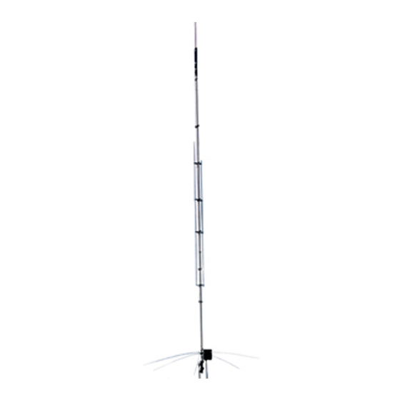
- Page 1 AV-640 8 Band Vertical Antenna INSTRUCTION & ASSEMBLY MANUAL WARNING: You can be killed if the antenna, feedline, or the equipment used to install the antenna accidentally contacts utility lines. Never install an antenna near utility lines. 308 Industrial Park Road, Starkville, MS 39759...
-
Page 2: Table Of Contents
Theory of Operation AV-640 Specifications Antenna Location Antenna Mast Antenna Grounding Antenna Guying Customer Supplied Components Tools Required for Assembly Safety Precautions Verification of AV-640 Parts Assembly Procedure Installation Procedure Tuning Procedure Maintenance Technical Assistance Warranty Table of Illustrations Illustration... -
Page 3: Introduction
No traps are used to achieve eight band performance. The AV-640 is resonant on 6, 10, 12, 15 and 17 meters with individual 3/8 wavelength radiators. The center radiator resonates on 20, 30 and 40 meters using parallel end loaded Teflon wire coils. -
Page 4: Av-640 Specifications
This is accomplished by a radio frequency choke in The center radiator of the AV-640 supports 1/4 wavelength stubs for 6 , 10, 12 and 17 meters. The stubs are placed approximately one tenth of a wavelength (electrically 1/8 wavelength) above the AV-640 base. -
Page 5: Antenna Location
While your own ingenuity and particular circumstances will determine the final mounting method, remember, any object within 75 Set torn the base of the antenna can influence the performance of the AV-640. WARNING: Always mount this antenna so that it is out of the reach of adults as well as children and pets. -
Page 6: Antenna Mast
Antenna Mast The recommended support mast for the AV-640 is steel water pipe between the sizes of 1- 1/4" OD to 2 1/2" OD and with a length that will place the antenna base at a safe height. Do not use thin walled conduit, aluminum tubing, or "TV" mast. The AV-640 is designed to operate at a height of 8 or more feet for proper performance. -
Page 7: Tools Required For Assembly
Tools Required For Assembly • 1/4" Standard Blade Screwdriver • 7/16" Nut Driver • #1 Phillips Screwdriver • 7/16" Open End Wrench #2 Phillips Screwdriver • 10 nun Open End Wrench 3/8" Open End Wrench • Tape Measure 20' 3/8" Nut Driver •... -
Page 8: Verification Of Av-640 Parts
Refer to the Box Contents and Parts Bags listings below to identify all parts. Also refer to Page 10 for drawings of the various brackets used in the AV-640. If any part is missing or damaged, turn to the Technical Assistance portion of this manual. There is extra hardware supplied with the antenna. - Page 9 Parts Bag Contents Instruction Manual Bag Part Number Part Description ID Number Quantity Received 925-AV640 AV-640 Instruction Manual MN . 925-0006 H -Gain Warrant Card 784-1780 Warning Label Parts Bag #1 Part Number Part Description ID Number Quanti Received 656-03755 6-32 x 3/8"...
- Page 10 180 Degree Stub Insulator Single Stub Insulator Dual Stub Base Bracket 90 Degree Stub Insulator P/N 738-2602 Qty (2) P/N 737-8100 Qty (5) P/N 735-1611 Qty (1) P/N 738-2600 Qty (2) Plastic Plastic Aluminum Plastic ID# P2 ID# P3 ID# SB2 ID# P1 Single Stub Base Bracket Radiator Clamp Bracket...
-
Page 11: Assembly Procedure
BD tubing section 6 inches (15 cm) into BC. Tighten hose clamp. ( ) Place (1) hose clamp (HC 1) over the slotted end of tubing section BD. Insert AV-640 Coil Assembly (LI) 4 inches (10 cm) into tubing section BD. Tighten hose clamp. - Page 12 TASK III Stub Insulator Assembly ( ) Place the AV-640 Radiator on a flat surface such as a driveway or garage floor. This will aid in mounting the Stub Insulators by keeping them aligned with each other. ( ) Refer to Figure D for Stub Insulator Assembly. There are three types of stub insulators: Single, 90 Degree and 180 Degree.
- Page 13 TASK V Stub Mounting ( ) Refer to Figure G to install the stub assemblies on the AV-640 Radiator. The bottom of each stub assembly can be slid into the corresponding top stub insulator and fed through consecutive insulators until it reaches the corresponding stub bracket.
- Page 14 6 Meter Stub ( ) If operation on 6 meters is desired, find the six meter stub (CH). Slide the threaded end of the stub through the top of the stub insulator as shown in Figure G. Continue through the second insulator until the stub meets the Stub Base Bracket. ( ) Mount the stub in the Stub Base Bracket hole using (2) 10-32 standard nuts (N2) and a #10 Lockwasher (W l) as shown in Figure G.
- Page 15 TASK VI Matching Unit Mounting ( ) Refer to Figure G for the mounting location of the Matching Unit (MU). Use the lower pair of bolts through the Base Insulator (IN) to mount the MU as shown in Figure G. Remove the (2) 1/4-20 nuts (N5) from the (2) 1/4-20 x 2" bolts (S8) previously installed.
-
Page 16: Installation Procedure
Page 17 and Figure J for more information. Installation The AV-640 antenna should be mounted at least 8 feet above ground. The main reason for this minimum height is safety. The AV-640 will work well at a minimum height of five feet but precautions from dangerous voltages must be taken. -
Page 17: Tuning Procedure
(Figure I). Tighten the antenna base in place. The AV-640 may be roof mounted on a tripod or similar support. Keep the AV-640 base a minimum of 5 feet above the roof surface. This minimum dimension is the same for any roof material type. -
Page 18: Maintenance
Maintenance The AV-640 should be inspected mechanically at least once a year. Normal wear and tear varies significantly with climate. Anti-Oxidation paste such as NoAIOX® or others can be applied to the radiator tubing sections. - Page 19 The packing material used to ship this antenna is designed to prevent shipping damage. Please reuse the original shipping carton if possible. Hy-Gain will not be responsible for shipping damage on returned items with improper packing.
-
Page 20: Figure A
FIGURE A AV-640 Center Radiator Assembly... - Page 22 FIGURE C Installation of AV-640 Stub Base Brackets...
-
Page 23: Figure D
FIGURE D Installation of Stub Insulators... -
Page 24: Figure E
FIGURE E Installation of Stub Insulators... -
Page 25: Figure F
FIGURE F Stub Assembly... -
Page 26: Figure G
Figure G Stub Installation... -
Page 28: Figure I
FIGURE I AV-640 Antenna Mounting Plate Assembly... -
Page 30: Warranty
Any evidence of alteration, erasure, or forgery shall be cause to void any and all warranty terms immediately. hy gain agrees to repair or replace at hy-gain's option without charge to the original owner any defective product under warranty, provided the product is returned postage prepaid to hy-gain with a personal check, cashiers check, or money order for $8.00 covering postage and handling.
Need help?
Do you have a question about the AV-640 and is the answer not in the manual?
Questions and answers