Table of Contents
Advertisement
Quick Links
Advertisement
Table of Contents

Related Manuals for THORLABS LM14S2


Summary of Contents for THORLABS LM14S2
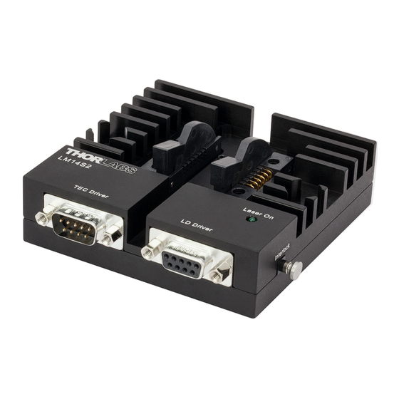
- Page 1 LM14S2 Butterfly Laser Diode Mount User Guide...
-
Page 2: Table Of Contents
4.3. Using the TEC / Laser Lockout Feature ................ 7 4.4. Operating the Butterfly Laser Diode ................7 4.5. Laser Controller Connection ..................7 4.5.1. Using the Thorlabs LDC Series Laser Controllers ..............7 4.5.2. Using a Third-Party Laser Controller ..................7 ... -
Page 3: Chapter 1 Warning Symbol Definitions
Butterfly Laser Diode Mount Chapter 1: Warning Symbol Definitions Chapter 1 Warning Symbol Definitions Below is a list of warning symbols you may encounter in this manual or on your device. Symbol Description Direct Current Alternating Current Both Direct and Alternating Current Earth Ground Terminal Protective Conductor Terminal Frame or Chassis Terminal... -
Page 4: Chapter 2 Safety
Butterfly Laser Diode Mount Chapter 2: Safety Chapter 2 Safety WARNING Always observe proper laser safety when operating this unit. Page 2 10614-D02... -
Page 5: Chapter 3 Description
Easy to use configuration cards allow the laser mount to be configured for all possible laser pin assignments. Designed primarily for Laser Diodes, the LM14S2 can also be used with many two port Electro-optic devices that are in 14-pin butterfly packages. -
Page 6: Chapter 4 Setup
4.1. Setup Instructions Note: The following procedure applies to installing and using a butterfly laser diode with the LM14S2. For information regarding electro-optic devices other than laser diodes, please refer to Section 10.2 AFTER reviewing these instructions for configuration card and device installation. -
Page 7: Configuration Cards
Configuration Cards The LM14S2 is shipped with two configuration cards needed to program the unit for the proper pin-outs for the type of laser being installed in the mount. In most cases, the dual Type 1 / Type 2 Configuration Card can be used to route the DB9 input signals to the mounted laser diode. -
Page 8: Configuration Card Pin-Outs
Butterfly Laser Diode Mount Chapter 4: Setup 4.2.1. Configuration Card Pin-Outs Refer to the following diagrams to determine which type of configuration card to use with your laser diode. MONITOR MONITOR DIODE* DIODE THERMISTOR CASE LASER LASER DIODE DIODE* Figure 3 Type 1 Pump Laser Diode (View shows alternate locations for monitor and laser diodes.) MONITOR DIODE LASER... -
Page 9: Using The Tec / Laser Lockout Feature
Operating the Butterfly Laser Diode Once the butterfly laser diode is properly mounted in the LM14S2, set the operating temperature using the TEC controller. Once the set temperature has been reached, enable the laser diode, set the drive current or power level, and control as you normally would. -
Page 10: Tec Controller Connection
4.6.1. Using the Thorlabs TED200C Controller The LM14S2 is best used with Thorlabs TED200C or related TEC controllers. The TED200C is shipped with a mating DB9 cable that plugs directly into the controller and laser mount. Using the cable supplied with the TED200C, the controller cannot be connected incorrectly. -
Page 11: Chapter 5 Operation
RF Modulation The LM14S2 has a Bias-T adapter to provide an RF input for modulating the laser with an external RF source up to 500 MHz. The adapter has a 25 Ω input that is AC-coupled directly to the laser through a Bias-T network. This adapter will only work with butterfly lasers specifically designed with an integrated blocking inductor and an additional 25 Ω... -
Page 12: Status And Interlocks
There are no serviceable parts in the LM142. The housing may be cleaned by wiping with a soft damp cloth. If you suspect a problem with your LM14S2, please call Thorlabs Tech Support and an engineer will be happy to assist you. -
Page 13: Chapter 6 Safety Interlock Connections
Safety Interlock Connections The LM14S2 is equipped with a Remote Interlock Connector located on the side panel. In order to enable the laser driver, a short circuit must be applied across the terminals of the Remote Interlock Connector. In practice, this connection is made available to allow the user to connect a remote actuated switch to the connector (i.e. -
Page 14: Chapter 7 Troubleshooting
Laser Wavelength or Power is Unstable Even Though the TEC Controller Shows Stable Temperature Directions Possible Solution Make sure your laser diode is fully inserted into the LM14S2 laser mount and its LD is not fully seated body is in full contact with the heat sink base, and the four securing screws are tightened. -
Page 15: Chapter 8 Specifications
Butterfly Laser Diode Mount Chapter 8: Specifications Chapter 8 Specifications Performance Specifications Laser Specifications Lasers Supported 14 Pin-Butterfly Maximum Laser Current Laser Pin Configurations User Configurable 100 kHz to 500 MHz RF Modulation Frequency RF Input Connection RF Input Impedance 25 Ω... -
Page 16: Chapter 9 Mechanical Drawing
Butterfly Laser Diode Mount Chapter 9: Mechanical Drawing Chapter 9 Mechanical Drawing Page 14 10614-D02... -
Page 17: Chapter 10 Appendix
Figure 8 NEL Type STB Laser In its normal configuration, the LM14S2 has an open connection to Pin 12 of the laser diode ZIF socket. This is done to prevent conflicts while using the Bias-T adapter on Type 2 laser diodes with internal Bias-T components (see Figure 5). - Page 18 In order to make the necessary connections between the DB9 input connectors and the ZIF socket, you will need to use the Custom Configuration Card provided with the LM14S2. Please review Sections 4.1 and 4.2. When installing the EO device, please observe proper device polarity by orienting the device’s pins with the pins on the ZIF sockets according to the pin designations printed to the side of each ZIF socket.
-
Page 19: Chapter 11 Regulatory
Waste Treatment is Your Own Responsibility If you do not return an “end of life” unit to Thorlabs, you must hand it to a company specialized in waste recovery. Do not dispose of the unit in a litter bin or at a public waste disposal site. -
Page 20: Thorlabs Worldwide Contacts
Fax: +46-31-703-40-45 www.thorlabs.de www.thorlabs.com Email: europe@thorlabs.com Email: scandinavia@thorlabs.com France Brazil Thorlabs SAS Thorlabs Vendas de Fotônicos Ltda. 109, rue des Côtes Rua Riachuelo, 171 78600 Maisons-Laffitte São Carlos, SP 13560-110 France Brazil Tel: +33 (0) 970 444 844 Tel: +55-16-3413 7062... - Page 22 www.thorlabs.com...
Need help?
Do you have a question about the LM14S2 and is the answer not in the manual?
Questions and answers