
Related Manuals for Leadshine STEPPERONLINE DM320T


Summary of Contents for Leadshine STEPPERONLINE DM320T
- Page 1 User Manual DM320T 2-Phase Digital Stepper Drive #7 Zhongke Road, Jiangning, Nanjing, China T: 0086-2587156578 Web site: www.omc-stepperonline.com E-Mail: sales@stepperonline.com...
-
Page 2: Table Of Contents
Digital Stepper Drive DM320T Table of Contents 1. Introductions..................................1 1.1 Features.................................. 1 1.2 Applications................................1 2. Specifications..................................1 2.1 Electrical Specifications............................1 2.2 Environment................................2 2.3 Mechanical Specifications............................2 2.4 Elimination of Heat..............................2 3. Connection Pin Assignments and LED Indication......................3 3.1 Connector P1 Configurations..........................3 3.2 Connector P2 Configurations..........................3 3.3 LED Light Indication.............................. -
Page 3: Introductions
Digital Stepper Drive DM320T 1. Introductions The DM320T is a digital stepper drive with simple design and easy setup. By implementing advanced stepper control technology, this stepper drive is able to power 2-phase and 4 phase stepper motors smoothly with optimal torque and low motor heating &... -
Page 4: Environment
Digital Stepper Drive DM320T 2.2 Environment Cooling Natural Cooling or Forced cooling Environment Avoid dust, oil fog and corrosive gases 0°C - 65°C (32°F - 149°F) Ambient Temperature Operating Environment Humidity 40%RH-90%RH Operating Temperature 0°C - 50°C (32°F - 122°F) 10-50Hz / 0.15mm Vibration Storage Temperature... -
Page 5: Connection Pin Assignments And Led Indication
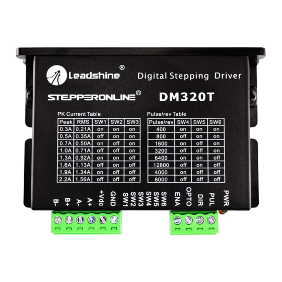
Digital Stepper Drive DM320T 3. Connection Pin Assignments and LED Indication The DM320T has two connector blocks P1&P2 (see above picture). P1 is for control signals connections, and P2 is for power and motor connections. The following tables are brief descriptions of the two connectors. More detailed descriptions of the pins and related issues are presented in section 4, 5, 9. -
Page 6: Led Light Indication
Digital Stepper Drive DM320T Warning Warning: Don’t plug or unplug the P1 & P2 terminal block to avoid drive damage or injury when DM320T is powered on. 3.3 LED Light Indication There are two LED lights for DM320T. The GREEN one is the power indicator which will be always on generally. The RED one is a protection indicator which will flash 1-2 times in a 3-second period, when protection enabled for a DM320T. -
Page 7: Motor Connection
Digital Stepper Drive DM320T 5. Motor Connection The DM320T can drive 2-phase and 4-pahse bipolar hybrid stepper motors with 4, 6, or 8 wires. 5.1 Connections of 4-lead Motor The 4 lead motors are the least flexible and easy to connect. And the Speed – torque of motor depends on winding inductance. -
Page 8: Connections Of 8-Lead Motor
Digital Stepper Drive DM320T Figure 6: 6-lead motor full coil (higher torque) connections 5.3 Connections of 8-lead Motor 8 lead motors offer a high degree of flexibility to the system designer in that they may be connected in series or parallel, thus satisfying a wide range of applications. -
Page 9: Regulated Or Unregulated Power Supply
Digital Stepper Drive DM320T driven motor (particularly at lower speed). Higher supply voltage will allow higher motor speed to be achieved, at the price of more noise and heating. If the motion speed requirement is low, it’s better to use lower supply voltage to decrease noise, heating and improve reliability. -
Page 10: Current Configurations
Digital Stepper Drive DM320T Microstep Steps/rev.(for 1.8°motor) 1600 3200 6400 12800 4000 8000 7.2 Current Configurations For a given motor, higher drive current will make the motor to output more torque, but at the same time causes more heating in the motor and drive. Therefore, output current is generally set to be such that the motor will not overheat for long time operation. -
Page 11: Wiring Notes
Digital Stepper Drive DM320T 8. Wiring Notes In order to improve anti-interference performance of the drive, it is recommended to use twisted pair shield cable. To prevent noise incurred in PUL/DIR signal, pulse/direction signal wires and motor wires should not be tied up ... -
Page 12: Protection Functions
Digital Stepper Drive DM320T Figure 10: Sequence chart of control signals Remark: t1: ENA must be ahead of DIR by at least 5s. Usually, ENA+ and ENA- are NC (not connected). See “Connector P1 Configurations” for more information. t2: DIR must be ahead of PUL effective edge by 5s to ensure correct direction; t3: Pulse width not less than 7.5s;... -
Page 13: Troubleshooting
Digital Stepper Drive DM320T 12. Troubleshooting In the event that your drive doesn’t operate properly, the first step is to identify whether the problem is electrical or mechanical in nature. The next step is to isolate the system component that is causing the problem. As part of this process you may have to disconnect the individual components that make up your system and verify that they operate independently.
Need help?
Do you have a question about the STEPPERONLINE DM320T and is the answer not in the manual?
Questions and answers