Table of Contents
Advertisement
Quick Links
Advertisement
Table of Contents

Summary of Contents for INVENTIA MT-101
- Page 2 Telemetry Module MT-101 User’s Manual GSM/GPRS Telemetry Module for monitoring and control Class 1 Telecommunications Terminal Equipment for GSM 850/900/1800/1900 v1.43 INVENTIA Sp. z o.o...
- Page 3 Version 1.43 Warsaw, April 2008 Please, note! This User’s Manual is related to the version 1.43 of the firmware software of the MT-101 Telemetry Module. Versions older than the one described in the Manual may not support all the features.
-
Page 4: Table Of Contents
Index 1. Introduction ......................8 2. Module’s destination ....................9 3. GSM requirements ....................9 4. Module’s design...................... 10 4.1. Topography ..................... 10 4.2. Resources ....................... 10 4.2.1. Binary inputs ..................... 11 4.2.2. Analog inputs ..................... 11 4.2.3. Binary outputs ................... 11 4.2.4. - Page 5 8.2.1.3. Module serial number ................33 8.2.1.4. IMEI number ..................33 8.2.1.5. Internal program version ............... 34 8.2.1.6. Configuration file version ............... 34 8.2.1.7. Configuration identifier ................34 8.2.1.8. Last configuration date ................34 8.2.1.9. Last read of device time ................ 34 8.2.2.
- Page 6 8.2.5.3. Modbus RTU Slave mode ............... 49 ………………………………………………………………………… 8.2.5.3.1. Routing table size ………………………………………………………………………………. 8.2.5.3.2. Routing table 8.2.5.4. Modbus RTU Mirror mode ..............50 …………………………………………………………………. 8.2.5.4.1. Number of data blocks ……………………………….. 8.2.5.4.2. Delay after error in communication with SLAVE …………………………………………………………………………. 8.2.5.4.3. Data block 1...16 8.2.5.4.3.1.
- Page 7 8.2.6.2.1.2. Operating modes ..............61 8.2.6.2.1.2.1. Binary input ............... 62 8.2.6.2.1.2.1.1. Filtering constant ............62 8.2.6.2.1.2.2. Analogue inputs ..............62 8.2.6.2.1.2.2.1. Engineering units ............62 8.2.6.2.1.2.2.2. Low reference - internal units ......... 62 8.2.6.2.1.2.2.3. Low reference - engineering units ........63 8.2.6.2.1.2.2.4.
- Page 8 ……………………………………………………………………………………….. 8.2.6.3.3. Stop bits …………………………………………………………………………………………… 8.2.6.3.4. Parity 8.2.6.4. Asynchronous clocks ................74 ……………………………………………………………………….. 8.2.6.4.1. Clocks TMR1, TMR2 8.2.6.4.1.1. Period ..................74 8.2.6.5. Synchronous clocks ................75 ………………………………………………………………………… 8.2.6.5.1. Clock TMR3, TMR4 8.2.6.5.1.1. Start ..................75 8.2.6.5.1.2. Period ..................75 8.2.6.6. Logger ....................75 …………………………………………………………………………...
- Page 9 9.3. Main window layout ..................89 9.3.1. Menu items ....................89 9.3.1.1. File ..................... 89 9.3.1.2. Module ....................90 9.3.1.3. Help ....................94 9.3.1.4. Toolbar ....................95 9.4. Program editor table ..................95 9.5. Standard functions ................... 95 9.6. Numeric keyboard .................... 96 9.7.
- Page 10 12.3. Explosive environment .................. 128 13. Appendices ......................128 13.1. Data transmission in GSM systems ..............128 13.1.1. SMS ...................... 128 13.1.2. CSD (HSCSD) ..................128 13.1.3. GPRS ....................129 13.1.3.1. Advantages of GPRS technology ............129 13.1.3.2. GPRS in telemetry applications ............129 13.1.4.
-
Page 11: Introduction
In providing this user’s manual, we are aware that it will not answer all your questions and address all your doubts. This is why the manual will be regularly supplemented and modified. We ask for your comments and welcome suggestions in order to make this manual more useful. INVENTIA Ltd. -
Page 12: Module's Destination
• Spontaneous transmission of data on occurrence of pre-defined alert states enabling application on objects requiring continuous monitoring. A typical application field for MT-101 are all installations requiring local control and transmission of data to remote monitoring center. We encourage getting acquainted with the modules' configuration and modes of operation along with examples of application in different configurations described in appendices. -
Page 13: Module's Design
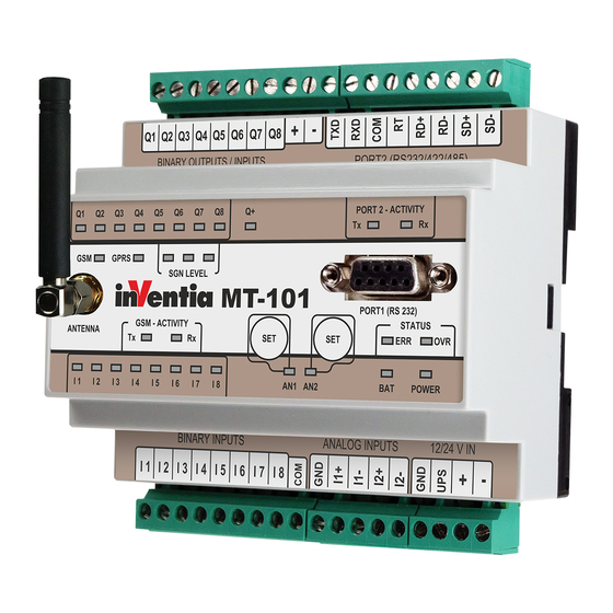
4. Module’s design 4.1. Topography 4.2. Resources MT-101 module's resources working as: • binary input DI - binary inputs • counter input (max.16) • analogue input F/U working as: • binary otput DO - binary • binary input outputs • counter input •... -
Page 14: Binary Inputs
4.2.1. Binary inputs The MT-101 Telemetry Module is equipped with 8 dedicated binary inputs marked as I1 – I8. The inputs support both positive and negative logic. Additionally, up to 8 binary inputs are available if binary outputs, Q1 – Q8, are configured to work in the binary input mode. -
Page 15: Serial Ports
That makes the hardware universal in application. 4.2.4. Serial ports MT-101 Telemetry Module is equipped with two serial ports PORT1 and PORT2. PORT1 works only in RS232 mode and is dedicated to local configuration of parameters. In order to perform local configuration, connect this port to a PC-class computer with running MTM program. -
Page 16: Internal Resources
4.3. Internal resources 4.3.1. Registers MT-101 Telemetry module has in it's internal resources 16 bit input registers and 16 bit internal registers. Remote access to these areas is possible using standard Modbus commands. Internal Registers are not reset at power off. -
Page 17: Mt2Mt Buffer
FS1_gprs = 1 - informs upon log off from GPRS network Full list of system variables is placed in Memory map chapter in Appendices. 4.4. LED diodes LED indicators placed on MT-101 front panel are convenient during module start up phase. -
Page 18: Set Buttons
Detailed description of signaling patterns is placed in chapter LED signaling. 4.5. SET buttons SET buttons placed on MT-101 front panel are for manual setting of auxiliary alarm thresholds for analogue inputs A1 and A2. Manually set thresholds can not be modified or read during configuration of module. -
Page 19: Sim Card
SIM cards operating in low potential technology 3,3V. 4.7. Antenna Attachment of antenna is essential for proper operation of MT-101 telemetry module. SMA socket is placed on module's front panel. The attached antenna has to secure appropriate radio signal level enabling login to GSM network. -
Page 20: Power Supply
4.9. Housing MT-101 module is encapsulated in standard housing made of plastic compliant with safety requirements and protecting the module in standard operating environment. The applied solution complies with standard industrial requirements for DIN rail mounting. -
Page 21: Binary Inputs/Outputs Q1....Q8
Binary inputs I1..I8 – in negative logic: Each of binary inputs I1..I8 may operate as a counter input or analogue input with frequency conversion to analogue value. The change of input operating mode is done during configuration. Typical connection for counting input is identical to standard input connection for both negative and positive logic. -
Page 22: Analog Inputs A1, A2
Binary inputs Q1..Q8 – in negative logic: Any of binary outputs Q1..Q8 may operate as counter input or analogue input with frequency conversion to analogue value. The change of input's operating mode is done during configuration. Typical connection for counting input is identical to standard input connection for positive logic. -
Page 23: Communication Ports
Analogue inputs A1, A2 – connection with passive output converter * in noisy environment, use independent supply for input-output circuits is recommended. 5.4. Communication ports Telemetry module is equipped with 2 communication ports for different applications. They are : PORT 1 (RS232 – configuration) •... - Page 24 PORT 2 (RS232/422/485 – communication) • The Port is optically-isolated, used for data exchange. • Maximal isolating voltage 60Vrms. • Operating mode selected by configuration application. Description Description transmitter output receiver input interface common ground (GND) terminator – if necessary connect to RD+ RD+, for RS485 (transmitter, receiver), for RS422 (receiver) SD+,...
-
Page 25: Power Supply
** - For AC supply polarisation does not apply. Example: Connection diagram with battery backup NOTICE! Due to MT-101 module's high momentary current consumption the supply must be capable of delivering >= 2A current. Improper power supply may result in faulty operation and damage the module! -
Page 26: Starting The Module
Even with no SIM inserted, the module exchanges information with available GSM networks in order to secure possibility of sending emergency calls (112). The antenna is connected to MT-101 module via SMA connector placed on the front panel of device. -
Page 27: First Configuration
6.2. First configuration First configuration of MT-101 is necessary for setting up basic parameters making logging to GSM network possible and, optionally, servicing GPRS. NOTICE! Since a new module or a module configured for other circumstances may not have necessary data for proper login to GSM network, it is necessary... -
Page 28: Inserting Sim Card
RESET of the module. Well/configured MT-101 module logs into GPRS network within 20 -30 seconds. The login sequence is displayed by diagnostic LEDs at the front panel of the module. Explanation of sequence is described in details in LED signaling chapter. -
Page 29: Module's Operating Modes
PORT2 other Slave devices employing same transmission protocol. • Modem Mode - enables (in justified cases) abandoning all functionality of MT-101 and using it as a plain, but automatically logging into selected network GSM/GPRS modem. -
Page 30: Mt Slave Mode
7.1. MT Slave mode MT Slave is the basic and default operating mode of MT-101 module. In this mode, the module makes all internal resources accessible and visible under Modbus ID defined in configuration. PORT2 is not serviced. Mode is employed where there is no need for communication with external devices via PORT2. -
Page 31: Modbus Rtu Slave Mode
• Frames are sent only to recipients having Modbus ID matching address received via PORT2. • All frames received at PORT2 are sent to recipients having Modbus ID=0 written in the table. • Frames with address 0 (broadcast frames) are set to all recipients declared in the routing table. -
Page 32: Modem Mode
This mode does not require configuration of any parameter beyond right PIN code but in turn does not give access to any MT-101 features except transmission control. Being able to use transmission control, modem may be reset if no activity is detected in defined time. -
Page 33: Transparent Plus Mode
GazModem mode is an extension of Modbus RTU Slave mode with functionality similar to that available in Modbus Mirror mode with mapping of register space of peripheral Slave into MT-101 internal registers. This mode was implemented due to requirement of reading from devices operating in Gaz- Modem and Gaz-Modem2 protocols created by Plum Sp. -
Page 34: Nmea 0183 Mode
Since MT-101 module has no capability of direct communication with M-Bus units it is necessary to connect an external converter to PORT2. The converter RM-120 is one of our products. 7.10. NMEA 0183 mode NMEA 0183 mode is an extension of Modbus RTU Slave mode with the function of receiving and interpreting of data in NMEA 0183 format sent by peripheral device attached to PORT2. -
Page 35: Configuration
8. Configuration 8.1. General information The configuration of MT-101 module, as is the case for other modules in the MT series, is carried out using the MTM (MT Manager) program portal, delivered free of charge to users of our telemetry solutions. -
Page 36: Header
8.2.1. Header Header of parameter structure describes MT-101 telemetry module. It holds basic information unique to the module, the configuration contained by module and configuration file version. Information displayed is not user editable and solely used for verification and information purpose. -
Page 37: Internal Program Version
8.2.1.5. Internal program version Function - displays the identification of actual version of internal telemetry module program (firmware) Data type - text Range - n/a, read-only parameter Comments - the value of this field changes automatically after download of firmware 8.2.1.6. -
Page 38: Mode Of Operation
Transparent mode allowing sending GPRS data to PORT2. Modbus RTU Master in this mode, the MT-101 module cooperates with external unit acting as System Modbus Master connected to PORT2. The module routing table assigns Slaves' Modbus IDs to IP addresses of their respective GPRS serving nodes in order to optimize transmission. -
Page 39: Sim Card's Pin Code
NMEA 0831 this mode is dedicated to NMEA 0831 protocol. Received data is stored in module's internal registers compliant to established standards. FlexSerial this mode enables integration of any kind of PLC controllers, I/O units, measurement equipment, operator panels equipped with serial communication port RS-232/422/485 on the base of programmed servicing of non standard protocols. -
Page 40: Configuration Password
Data type - selection list Range Unrestricted access for any IP address within the APN List Access limited to addresses defined in the list of Authorized numbers, IP for addresses with Configuration option set to Allowed. Default value Comments - Note that access restriction configuration applies only to GPRS connection and when used improperly may block remote access for users that should have the right to configure the module. -
Page 41: Data Overwriting Protection
8.2.2.8. Data overwriting protection Function - blocks writing of data into internal module registers, protecting data significant to proper operation of module. Data type - selection list Range Data writing is possible when password is provided Data writing to internal registers not protected. Default value Comments - This parameter protects the module against accidental or... -
Page 42: Use Sms
8.2.2.12. Use SMS Function - defines working sub-mode of module operating in GPRS Data type - selection list Range Module operating in GPRS mode has SMS services active. As a result, the GPRS session is suspended every 12 min. and the module checks for incoming text messages. -
Page 43: Gprs
8.2.3. GPRS GPRS Group encompasses parameters connected to login and data transmission in GPRS system. Parameters defined within this group are mandatory and optional as well as convenient for transmission optimization. 8.2.3.1. APN name Function - defines APN name selected for GPRS transmission Data type - text Range... -
Page 44: Set Ip
Default value - 0.0.0.0 Comments - Parameter mandatory in case of operating MT-101 module in GSM networks where operator uses dynamic address translation of internal addresses to static external addresses visible to external users. The parameter enables placing the external IP address under which the internal network node is visible in the header for sent data frame. -
Page 45: Transmission Timeout
8.2.3.9. Transmission timeout Function - Defines waiting time (in seconds) for confirmation of reception of sent data frame. Data type - number Range - 0..655 [s] Default value - 12 [s] Comments - This value in connection with declared Number of GPRS transmission retries defines max. -
Page 46: Number Of Login Retries
Data type - IP address field Range - 0.0.0.0 - 255.255.255.255 Default value - 0.0.0.0 Comments - This parameter sets recipient's address for data frames testing GPRS transmission channel sent after defined Idle time elapses. Leaving recipient address at 0.0.0.0 sends data frames to module's own IP address. -
Page 47: Proxy Server Ip Address
8.2.3.15. Proxy server IP address Function - inserts Proxy server IP for selected Proxy Data frame format. Data type - IP address field Range - 0.0.0.0 - 255.255.255.255 Default value - 0.0.0.0 Comments - inserted IP is public static address of communication server serving modules working in GSM/GPRS network with dynamic IP assignment. -
Page 48: Number Of Ip Numbers
8.2.4.2. Number of IP numbers Function - Defines length of IP numbers list authorized to communicate with the module via GPRS. Particular IP addresses have defined privileges for access to configuration and sending data queries. Data type - number Range - 0..128 Default value Comments... -
Page 49: Mode Of Operation
In practice, only the group of parameters relevant for the selected mode will appear on the list. 8.2.5.1. Transparent mode MT-101 operating in Transparent mode sends all data received at PORT2 to IP addresses appointed during configuration. This is the standard operating mode employed as autonomic gateway between non- intelligent device connected to serial port using not supported by MT-101 protocol. -
Page 50: Channel Reservation Time
Range - 0,00..655,35 [s] Default 1 [s] value Comments - n/a 8.2.5.1.1.3. Channel reservation time Function - Defines (in seconds) the time of reservation of exclusive transmission channel to device from which the frame was received. Data type - number Range - 0,00..655,35 [s] Default... -
Page 51: Address Offset
CAUTION! When channel reservation and Routing are used simultaneously, channel reservation has higher priority. Routing table is used only without channel reservation! In case of channel reservation, all frames are sent to one recipient regardless format and length of the frame. After channel is released (after channel reservation time has elapsed), the recipient is found on the basing of the address field of received frame. -
Page 52: Modbus Rtu Master Mode
8.2.5.2. Modbus RTU Master mode MT-101 Module operating in Modbus RTU Master mode receives data sent by peripheral device operating in Modbus RTU Master mode at PORT2. Data are sent via GPRS to remote Slave devices according to routing table. -
Page 53: Routing Table Size
8.2.5.3.1. Routing table size Function - Defines size of routing table Data type - number Range - 1..255 Default value Comments - the length of routing table should not be shorter than number of network nodes the module communicates with. 8.2.5.3.2. -
Page 54: Data Block 1...16
Time is counted independently for each defined area (Slave device) and reduces only the frequency of querying for areas with communication errors. Data type - number Range - 1..65535 [s] Default 15 [s] value Comments - Increasing this value reduces influence of malfunctioning devices on communication with other devices but decreases statistic time to reestablish communication after removal of error cause. -
Page 55: Address Of Mapped Space In Slave
Data type - number Range - 0..999 Default value Comments - n/a 8.2.5.4.3.4. Address of mapped space in SLAVE Function - Defines address of first register mapped from peripheral Slave device. Data type - number Range - 0..65535 Default value Comments - n/a 8.2.5.4.3.5. -
Page 56: Max. Length Of Data Packet
8.2.5.5.1. Max. length of data packet Function - Defines (in bytes) max. data volume in a packet. When reception buffer reaches declared value, the packet will be dispatched. Data type - number Range - 0..1408 Default value Comments - n/a 8.2.5.5.2. -
Page 57: Gazmodem Mode
8.2.5.6. GazModem mode CAUTION! Option discontinued from v 1.43 of firmware for module MT-101. The description is solely for legacy support . MT-101 Module operating in GazModem mode enables communication with gas counters operating on GazModem transmission protocol. Data received at PORT2 are placed in respective registers of MT-101 module's memory map. -
Page 58: Alarm Station Ip Address
Range - 0,01...100,00 [%] Default - 2,00 [%] value Comments - setting of value of hysteresis adequate to signal variations prevents untimely activations of alarm flags. 8.2.5.6.5. Alarm station IP address Function - defines alarm recipient's IP address. Data type - selection list Range - friendly names assigned to IP addresses of devices declared in... -
Page 59: Signal Reading
Range Reading active Reading inactive Default value Comments - n/a 8.2.5.6.7.3. Signal reading Function - defines status of signal reading from gas meter Data type - selection list Range Signal reading inactive 1 byte Read 1 signal byte in Gaz-Modem protocol 2 bytes Read 2 signal bytes in Gaz-Modem protocol 3 bytes... -
Page 60: M-Bus Lec Mode
Data received at PORT2 is placed in dedicated registers of the memory map of MT-101. Additionally, in this mode it is possible to attach a gas meter to PORT1 of the MT-101 module. After selecting this mode, local configuration is possible during the first 30s after power-up - PWR LED is flashing. -
Page 61: Threshold Hysteresis
8.2.5.7.4. Threshold hysteresis Function - Defines hysteresis for alarm thresholds values Data type - number Range - 0,01...100,00 [%] Default - 5,00 [%] value Comments - setting of value of hysteresis adequate to signal variations prevents untimely activations of alarm flags. 8.2.5.7.5. -
Page 62: Number Of Devices
Range - 0,01..10,00 [s] Default - 2,00 [s] value Comments - This value along with declared Number of transmission retries to gas meter influences max. time of single data packet transmission. 8.2.5.7.9. Number of devices Function - Defines number of declared register spaces (devices) read on PORT2 from peripheral devices operating on M-Bus protocol. -
Page 63: Nmea 0183 Mode
Default value Comments - n/a 8.2.5.9. FlexSerial In FlexSerial mode MT-101 module can service units connected to PORT2 that employ non standard protocols. More about FlexSerial mode... 8.2.5.9.1. Max. length of data packet Function - defines (in bytes) max length of data packet in receiving buffer. -
Page 64: Resources
Final functionality of each input depends on settings and configuration parameters connected. 8.2.6.2.1. Binary inputs I1,..I8 Module MT-101 has eight identical Binary inputs. Inputs can operate in one of three functional modes: • Standard binary input •... -
Page 65: Binary Input
Default Binary input value Comments - selecting appropriate operating mode is the basis for taking full advantage of module capabilities. It has an influence on available configuration parameters optimizing module performance. 8.2.6.2.1.2.1. Binary input 8.2.6.2.1.2.1.1. Filtering constant Function - Defines (in seconds) value of min. duration of altered state on input in order to consider state to be stable. -
Page 66: Low Reference - Engineering Units
Default value Comments - low reference point for internal units 8.2.6.2.1.2.2.3. Low reference - engineering units Function - used along with other reference parameters for rescaling input signal range to engineering units range. Data type - number Range - 0..65535 Default - 400 value... -
Page 67: Alarm Lo
Range - 0..65535 [engineering units] Default - 0 [engineering units] value Comments - Sets A Hi flag used for rules processing. The reset level for this flag depends on Alarm hysteresis value. 8.2.6.2.1.2.2.8. Alarm Lo Function - Defines Lo alarm level in engineering units for analogue input signal. -
Page 68: Counter Inputs
binary inputs space is raised and may be used for rules processing. 8.2.6.2.1.2.3. Counter inputs 8.2.6.2.1.2.3.1. Counting direction Function - defines counting direction Data type - selection list Range A pulse on input increases value of counter register Down A pulse on input decreases value of counter register Default value Comments - The counting process is valid only within range of Counting... -
Page 69: Binary Outputs Q1....Q8
8.2.6.2.2. Binary outputs Q1..Q8 MT-101 Module has eight functionally identical Binary outputs. These inputs can operate in one of four modes: • standard binary input •... -
Page 70: Analogue Inputs
Range - 0,00..163,83 [s] Default - 0,1 [s] value Comments - Setting value appropriate to contact characteristics eliminates disturbance caused by contact bounce thus preventing multiple registration of what is in reality one pulse. 8.2.6.2.2.2.2. Analogue inputs Function - Defines time of measuring frequency of input signal in order to convert it to analogue value. -
Page 71: High Reference - Internal Units
8.2.6.2.2.2.2.4. High reference - internal units Function - used along with other reference parameters for rescaling input signal range to engineering units range. Data type - number Range - 1..65535 Default - 65535 value Comments - high reference point for internal units 8.2.6.2.2.2.2.5. -
Page 72: Alarm Lolo
8.2.6.2.2.2.2.9. Alarm LoLo Function - Defines LoLo alarm level in engineering units for analogue input signal. Data type - number Range - 0..65535 [engineering units] Default - 0 [engineering units] value Comments - Sets An LoLo flag used for rules processing. The reset level for this flag depends on Alarm hysteresis value. -
Page 73: Counting Range
8.2.6.2.2.2.4. Binary outputs Binary outputs do not require any configuration. 8.2.6.2.3. Analogue inputs AN1, AN2 MT-101 Module is equipped with two identical Analogue inputs operating in 4-20mA standard. 8.2.6.2.3.1. Name Function - allows setting a friendly name for the input usually connected with performed function. -
Page 74: Operating Mode
Range - letters and numerals, max. 16 characters Default - Resource Name (A1, A2) value Comments - entering a friendly name facilitates distinguishing destination, performed function and required settings. 8.2.6.2.3.2. Operating mode Function - defines analogue inputs operating mode Data type - selection list Range Analogue input... -
Page 75: High Reference - Engineering Units
Range - 1..65535 Default - 65535 value Comments - high reference point for internal units 8.2.6.2.3.7. High reference - engineering units Function - used along with other reference parameters for rescaling input signal range to engineering units range. Data type - number Range - 1..65535... -
Page 76: Alarm Hysteresis
Range - 0..65535 [engineering units] Default - 0 [engineering units] value Comments - Sets An LoLo flag used for rules processing. The reset level for this flag depends on Alarm hysteresis value. 8.2.6.2.3.11. Alarm hysteresis Function - Defines alarm thresholds for hysteresis value of analogue signal (in engineering units). -
Page 77: Transmission Speed
8.2.6.3.2. Transmission speed Function - defines transmission speed ( bits/s) for serial port Data type - selection list Range 1200, 2400, 4800, 9600,19200, 38400 [b/s] List of supported speeds Default 9600 [b/sec] value Comments - n/a 8.2.6.3.3. Stop bits Function - defines number of stop bits Data type - selection list... -
Page 78: Synchronous Clocks
- selection list Range Logger active logger inactive Default value Comments - During MT-101 module operation, the state of Logger may be remotely altered by MLOG_act bit in binary outputs space. – active, – inactive. Upon start of the logger, the first record of actual state is... -
Page 79: Sampling Interval
logger content to defined recipient but only when it holds records with data. 8.2.6.6.2. Sampling interval Function - Defines (in seconds) the interval of checking module inputs state Data type - number Range - 0..1500 [s] Default - 0 [s] value Comments (zero) value results in sampling interval of 100ms... -
Page 80: Mt2Mt Buffer
Comments - since IP address of recipient is selected from list of friendly names, assigning unambiguous unique descriptive names is beneficial 8.2.6.7. MT2MT Buffer MT2MT Buffer enables creation of system where modules may exchange information (internal registers) with each other. Using buffer requires activation and defining register space where exchange is going to take place. -
Page 81: Constant Parameters
Range - 1..512 Default - 16 value Comments - received events registers laying outside defined space are not copied. 8.2.6.8. Constant parameters An option of defining Constant parameters under configuration was added for the user's convenience. Parameters are loaded to module memory during initialization of the module. -
Page 82: Number Of Sms Sending Rules
Adding more rules is done by setting the parameter number of SMS sending rules to desired value. 8.2.7.1.1. Number of SMS sending rules Function - declares number of SMS sending rules Data type - number Range - 1..32 Default value Comments - diminishing the number of rules does not delete settings until the configuration is written to the module. -
Page 83: Sms Text
Bi In 0->1, Bi In 1->0 Bi In Chg binary input state change Bi Out Err discrepancy between the forcing and output state Counter counter flip over (up or down) An LoLo, An Lo, An Hi, An HiHi, An Set Fall, An Set Rise An DB alarm threshold flags for analogue inputs signals Default value... -
Page 84: Data Sending
8.2.7.2. Data sending List of SMS sending rules can hold max. 32 entries defining data transmission conditions. A defined data block or Status will be sent to appointed IP address. Adding a new position is done in the context menu by right-clicking mouse while one of positions on the list is highlighted. -
Page 85: Trigger Flag
FS1_ups, FS1_q+, FS1_gprs system trigger inputs P1...P32 user program inputs TMR1, TMR2, TMR3, TMR4 synchronous and asynchronous clocks trigger inputs Default value Comments - more about trigger inputs and flags in chapter Appendices 8.2.7.2.1.1.2. Trigger flag Function - defines event triggering flag associated with selected trigger input Data type - selection list... -
Page 86: Buffer Address
Comments - n/a 8.2.7.3. CLIP calls CAUTION! This option is not supported starting with v 1.42 of the MT-101 module's firmware. The description is solely to support the legacy firmware. The term „CLIP call” describes attempts to establish a phone connection to a defined number. -
Page 87: Number Of Clip Calls Rules
Adding more rules is done by setting the parameter number of SMS sending rules to desired value. 8.2.7.3.1. Number of CLIP calls rules Function - declares number of CLIP calls rules Data type - number Range - 1..32 Default value Comments - diminishing the number of rules does not delete settings until the configuration is written to the module. -
Page 88: Clip Call Rule
8.2.7.3.4. CLIP call rule Each of rules residing on the list is defined by following parameters: • Trigger input • Trigger flag • Recipient number • Calling time 8.2.7.3.4.1. Trigger input Function - defines resource to observe Data type - selection list Range the rule is inactive I1..I8... -
Page 89: Calling Time
Default - NUM 1 - first number on the list value Comments - since recipient's phone number is selected from the list of friendly names, it is important to enter unique, unambiguous names facilitating identification. 8.2.7.3.4.4. Calling time Function - Gives an option to attach verbose device status to SMS message Data type - List... -
Page 90: Starting To Work
the MTProg application delivered free of charge to our customers, giving them th possibility of programming in integrated environments. Basic information regarding user programs functionality: • The program is executed cyclically every 100ms. • If the particular program cycle does not complete execution within 100ms, the next cycle will not start immediately but at the next 100ms round. - Page 91 APN server IP address of the computer routing data packets sent via internet. Internet connection When selected in conjunction with "RS-232 port", it sets up the communication via dial up GPRS connection or via routed Ethernet connection. This is the optimal way of communication between MTProg and remote modules. When unselected, it leaves the connection to GPRS modem and MTProg takes care of initializing modem and establishing connection.
-
Page 92: Main Window Layout
9.3. Main window layout Main program window displays a table containing the program to be executed by module's command interpreter. Right side of the window contains a field with button groups dedicated to defining operations and constants. On top, there is a system menu and a toolbar with icons for frequently used functions. -
Page 93: Module
Function "New" Erases the program visible in the table and the table is ready for editing of a new program. The icon on the toolbar performs same function. Function "Import" Writes a program previously stored on the hard disc into the table. Programs have a default extension ".MTp". - Page 94 and after connecting to the module with internal program running. Notice the green dot in lower left corner of the status bar. Function "Select" Presents the list of defined modules for selection of the desired module. The list has the option of selecting transmission mode via either RS232 cable or wireless (GPRS) connection using the module's IP address.
- Page 95 The table shows data written in system registers by MTManager application. MTProg application can only access modules previously defined and configured in active Project by MTManager. The icon on the toolbar performs same function. Function "Read program" Reads the content of module's program interpreter into the table. If the application is connected to the module, the control in the left side of the status bar is lit in red or green depending on the state of the program interpreter.
- Page 96 All introductory remarks concerning the connection and password protection of Read function are valid in this case as well. The process of writing program into module's interpreter is similar. The only difference appears in GPRS mode. After verification of privileges all lines of program are sent and the application waits for confirmations. The icon on the toolbar performs same function.
-
Page 97: Help
9.3.1.3. Help Function "Transmission" toggles transmission review window The title bar displays transmission type and recipient address while status bar displays connection status. The tool bar displays the icon closing the window. The main window's tool bar icon toggles transmission window display. Function "Settings"... -
Page 98: Toolbar
9.3.1.4. Toolbar The main window's toolbar holds icons corresponding to following menu functions: menu item "File" Function "New" menu item "File" Function "Red" menu item "File" Function "Write" menu item "Module" Function "Select" menu item "Module" Function "Connect/Disconnect" menu item "Module" Function "Read program"... -
Page 99: Numeric Keyboard
Top button row groups 4 logical operations of true/false type. Next group represents 6 functions comparing arithmetical values. Next 2 buttons represent assignment of arithmetical and logical values. Right column of numerical keyboard represent 4 standard arithmetical operations. 9.6. Numeric keyboard Numerical keyboard has all keys active only when selected function allows arithmetic input. -
Page 100: Auxiliary Functions
9.7. Auxiliary functions Some modules types and versions may implement auxiliary functions. Access to these functions is possible via the drop-down menu just above numerical keyboard: Detailed description of standard and auxiliary functions is located at chapter Description of program functions 9.8. - Page 101 Boolean NOT X get X get Y store result (bit) (bit) Is X greater than Y get X get Y store result (register) (register) (bit) get X > get Y get X <= get Y Is X lower than Y get X get Y store result...
- Page 102 Divide X by Y store result (register) = get X (register) / get Y (register) NOTICE !!! The function operates on integers. The result is truncated to integer. Crossing the valid range sets an error flag. Examples: 10 / 3 = 3 -15 / 4 = -3 Multiply X by Y store result (register) = get X (register) * get Y (register)
- Page 103 get X (register) = 1234 = 04D2 = 0000 0100 1101 0010 get Y (register) = 4991 = 137F = 0001 0011 0111 1111 store result (register) = 6061 = 17AD = 0001 0111 1010 1101 Bitwise NOT The function negates bits in the register. Example: decimal hexadecimal...
- Page 104 Bit test This function verifies whether at least one bit in get X register is set according to mask defined by get Y register. If confirmed, the function returns value 1 in store result column, else 0. Example: hexadecimal binary get X (register) 04D2 = 0000 0100 1101 0010 (value)
- Page 105 Copy block quickly The function copies data among blocks in internal registers space. Following parameters are used: register (get X) – source block address register (get Y) – block size register (store result) - destination block address Destination and source block may overlap. When block size exceeds the size of internal register space the data is not copied and the function rises an error flag.
- Page 106 Copy bigger value The function verifies which value, X or Y is higher and copies the higher one. get X > get Y than store result = get X get X <= get Y than store result = get Y Copy lower value The function verifies which value, X or Y is lower and copies the lower one.
- Page 107 Search for value in table The function scans the table (buffer) starting with register (get X) searching for value defined in (get Y) register. The table is searched for first occurrence of searched value or to the end of the memory space. If the value is found, the function returns an index to the register.
- Page 108 123.456.789.000 15 Error 123456 +000111.2 1112 1112 12.0000 Error 120000 12.0000 12000 12000 Convert number to text This function converts a binary value from register (get X) to text. The result is written into buffer starting with (store result) register. Separate text characters are stored in low order bytes of 16 bit registers.
-
Page 109: Description Of Internal Function Blocks
9.9. Description of internal function blocks 9.9.1. Timers T1...T8 EN_Tx RST_Tx REG_Tx PV_Tx x 10ms CAUTION! All variables in Modbus address space are updated after every cycle of internal program execution -that is every 100ms. -
Page 110: Counters C1...C8
9.9.2. Counters C1...C8 9.10. Signal levels or edges All logical input values may be additionally affected by a level or edge condition. The default value is a positive signal level. However, the user can change each of the input signals (Condition, Parameter X or Parameter Y) so that the program reacts to inverted value, rising edge, falling edge or change of state. - Page 111 keyboard or by clicking on the 0/1 values on the numerical keypad. After selecting the name of the variable, it is also possible to define the level or edge condition the execution of the function. Double-clicking with left mouse button causes a list of available functions to drop down.
-
Page 112: Verifying The Program
9.12. Downloading the program After completed editing of program, data can be sent to the module. The method of transmission depends on selected means of communication. When programming locally, it is necessary to establish RS232 cable connection. For remote programming, it is necessary that the computer on which MTProg is running has a network connection to the APN where the module resides. -
Page 113: The Counter
9.14.2. The counter MTProg has 8 counters of this type. The example illustrates a counter counting 10 activations of I1. Upon reaching the count of PV_C1 the flag C1 rises. Line 2 copies the state of C1 to output Q1. Change of Q1 may be used in the rule defining the data or sms transmission or in further programming. -
Page 114: Pumps Toggle Action
* - value 1 shifts between Q1 and Q2 depending on their state in last working cycle (if Q1=1 and Q2=0 then in next cycle it will shift to Q1=0 and Q2=1 The first program line resets REG1 to 0 (executed only on first scanning of program- later on omitted since the condition is not met). -
Page 115: Checking Bit's Value In The Registry
Q3 is running Q1 serves as auxiliary pump and so on.. 9.14.6. Checking bit's value in the registry In case of MT-101-to-MT-101 communication (the cascade system), it is necessary to test values of receiving module's registers holding the status received last via GPRS from sending module. -
Page 116: Alarm With Confirmation
As the result, the value of binary input I1 at sending module will be mirrored by receiving module's binary output Q1. Line 0 copies the bit 9 of RMT_IN into REG1. Line 1 compares REG1 to 256 (value of bit 9) and sets Q1 accordingly to the actual value. -
Page 117: Motion Detector
9.14.8. Motion detector The motion detector is connected to I1 and light source to Q1. When I1 is activated, the module turns the light on for 10 seconds. Repeated activation of I1 resets the time count back to 10 seconds. 9.14.9. -
Page 118: Problem Solving
10. Problem solving 10.1. LED signaling LED indicators placed on front panel of the MT-101 module are very convenient during start-up procedure. In order to understand their message please get acquainted with error codes. Click on the LED area you want to get information about. -
Page 119: Inputs/Outputs Q1....Q8
10.1.1. Inputs/Outputs Q1..Q8 LED indicators for outputs/inputs Q1..Q8 group signal both High state of forced output signal and High state of input signal in cases where output Q1...Q8 operates as binary input. Visual evaluation of current input/output state makes working with the module much easier. -
Page 120: Gsm Status
10.1.3. GSM status GSM Status LEDs indicate: GSM LED- reflects current login to GSM network state. • lit - the module not logged in • flashing with app. 2 Hz frequency - the module is logged in GPRS LED - when lit, signifies proper login to APN. LED indicators for GSM Status group reflect module's readiness to perform its duties. -
Page 121: Gsm Signal Level
10.1.5. GSM signal level LED indicators of GSM Signal level display information received from GSM network on signal level in the place where the antenna is mounted. It is presumed that for reliable operation at least one LED is lit. Lower level signal does not guarantee reliable operation and means that antenna placement should be changed or the antenna should be replaced with one securing higher signal level. -
Page 122: Module's Status
• The Module operates in Modbus RTU Master mode and communicates with attached Master device, passing GPRS received data. • The Module operates in Modbus RTU Slave mode and has sent received query to PORT 2 for Modbus ID different than its own •... -
Page 123: Set1, Set2 Alarm Thresholds
• Bat LED - is lit when the potential on UPS input falls below 13,8V. Since this input is used to signal main supply failure, the system flag FS1_ups is raised simultaneously. The FS1_ups flag may be used in rules processing. •... -
Page 124: Error Signaling
PUK code. Unfortunately this cannot be performed in the MT-101 module. The PUK code may by inserted only after taking the SIM card out of MT-101 module and placing it in a standard GSM mobile phone. The phone will demand entering of PUK code at power-up. -
Page 125: Standard Errors
10.3.1. Standard errors A sign of Standard error occurrence is a lit ERR LED. Error code numbers are displayed on signal level and GPRS LEDs. When GPRS LED is off the module is automatically trying reinitiate transmission. When GPRS LED is flashing user intervention is required. Remove the reason for error and recycle the power. -
Page 126: Critical Errors
10.3.2. Critical errors A sign of Critical error is the flashing of ERR LED. Error code numbers are displayed on signal level and GPRS LEDs. Occurrence of any errors described above indicates either a fault in program or a module defect. -
Page 127: Gsm/Gprs Modem
11.2. GSM/GPRS Modem Data for WISMO Quick 2406B Modem type WISMO Quick 2406B Dual Band GSM/GPRS module EGSM900/1800 Frequency range (EGSM 900 MHz) Transmitter: from 880 MHz to 915 MHz Receiver: from 925 MHz to 960 MHz Peak transmitting power (EGSM 900 MHz) 33 dBm (2W) –... -
Page 128: Binary Inputs I1....I8
Due to high momentary current consumption the power supply must be capable of delivering >= 2A of current. Inappropriate power supply may result in faulty operation or cause damage to MT-101 module! 11.4. Binary inputs I1..I8 Input voltage range -36 ... 36V Input resistance 5,4 kΩ... -
Page 129: Drawings And Dimensions
11.7. Drawings and dimensions... -
Page 130: Safety Informations
NOTE! All dimensions are in millimeters! 12. Safety information 12.1. Working environment When deploying telemetry modules one has to observe and comply to local legislation and regulations. Using the telemetry module in places where it can cause radio noise or other disturbances is strictly prohibited. -
Page 131: Hearing Aids
12.2.2. Hearing aids In rare cases the signal emitted by the telemetry module's antenna may disturb hearing aids functions. Should that occur, one has to study detailed operating instructions and recommendations for that particular product. 12.2.3. Other medical equipment Any radio device including the telemetry module may disturb the work of electronic medical equipment. -
Page 132: Gprs
This type of data transmission justifiable when large amounts of data are to be transmitted but would be extremely expensive in real time monitoring since it occupies the channel all of the time. 13.1.3. GPRS „General Packet Radio Services” – a technology of transmitting data as addressed digital packets. -
Page 133: Edge
14,4 Mb/s speed. 13.2. Application examples This chapter shows basic configurations of systems employing MT-101 modules. 13.2.1. Communication with single module This is the simplest possible monitoring system based on transmission of SMS messages by MT modules in case of event defined during module configuration. -
Page 134: Point To Point Communication
In this system, the MT-101 module set to Modbus RTU Mirror mode can be used. The module generates events based on data read from slave device connected to PORT 2 and mirrored into modules internal registers. This method significantly extends the number of inputs/outputs responsible for generation of events 13.2.2. - Page 135 Set Modbus ID number of the module to a value different than zero (f.e.1) Set Authorized IP to 1 and add the IP assigned to module MT-101 operating in Modbus RTU Master mode (options allowing data transmission and reception have to be checked in).
-
Page 136: Data Transmission From External Devices
After setting configuration parameters and connecting of device to PORT 2 of the module, the user obtains access to current data and alarms stored continuously in module memory. In this setup, MT-101 module may act as a concentrator for 16 devices. -
Page 137: Configuration For M-Bus Lec Mode
13.2.2.2.3. Configuration for M-Bus Lec mode The system consisting of MT-101 modules in Mbus LEC mode integrates dispersed objects in heat consumption metering systems equipped with electronic counters into a centralized measuring system. After setting configuration parameters and connecting of device to PORT 2 of the module, the user obtains access to current data and possibility of defining alarm thresholds continuously stored in module memory. -
Page 138: Syntax For Reading And Writing Data In Sms Mode
13.3. Syntax for reading and writing data in SMS mode Basic syntax: Reading #[representation][internal resource]/[% space address] Writing #[representation][internal resource]/[% space address]=value The value may be variable or constant. It is for example possible to send an SMS resulting in assigning the state of I1 to Q1 (#Q1=I1 or #Q1=#I1). Using second form replaces #I1 with the current value f.e. -
Page 139: Unlocking Writing To Internal Registers
Decimally: 5, 113, 6, 0, 'A', 'B', 'C', 'D', 'E', 0, 152, 112 13.5. Working with dynamic IP addressing In order to configure MT-101 module to work in Proxy mode do following: • In MTManager select Data frame format: Proxy •... -
Page 140: Data Formats
]--> 13.6. Data formats MT-101 module gives the user a choice of data frame format : • standard - standard operating mode. The units communicate directly with each other in the APN using static IP addresses allocated permanently to used SIM cards. In this mode, IP addresses of communicating modules are written into authorized units lists. -
Page 141: Module's Status Format
13.7. Module's Status format Status frame of MT-101 module is a sequence of four 16 bit registers from internal registers space (read command 03H, write 06H or 10H). 0x03E4... -
Page 142: Flags
Asynchronous clocks TMR1,TMR2 and synchronous TMR1...TMR4 TMR3, TMR4 13.9. Flags During operation MT-101 module governs a number of binary flags (assuming value True or False) that trigger rules processing and remote diagnostics. The User has access to following flags:... -
Page 143: Rm-120
Flag assuming value True if value of analogue input is Analogue higher than value set as Alarm HiHi(preserving relation to inputs hysteresis) An HiHi I1...I8 Q1...Q8 A1, A2 Analogue Flag assuming value True if value of analogue input crosses inputs defined deviation of previous central value An DB I1...I8... - Page 144 RS232 sender input RS232 circuit ground optional signaling for computers COM connection (not used for MT module) RS232 circuit ground...
-
Page 145: Memory Map
13.11. Memory map 13.11.1. Binary inputs space Binary inputs (bit addressable - command 02) Virtual Address Description Registers 0x0000 Pin state Q1...Q8 VREG_BI0 0x0008 Pin state I1...I8 Error messages for outputs 0x0010 ERR_Q1 ERR_Q2 ERR_Q3 ERR_Q4 ERR_Q5 ERR_Q6 ERR_Q7 ERR_Q8 Q1..Q8 Threshold bits... - Page 146 Counter flip over for inputs 0x0030 F_CNT_Q1 F_CNT_Q2 F_CNT_Q3 F_CNT_Q4 F_CNT_Q5 F_CNT_Q6 F_CNT_Q7 F_CNT_Q8 Q1..Q8 VREG_BI3 Counter flip over for inputs 0x0038 F_CNT_I1 F_CNT_I2 F_CNT_I3 F_CNT_I4 F_CNT_I5 F_CNT_I6 F_CNT_I7 F_CNT_I8 I1..I8 0x0040 Counter outputs C1 .. C8 VREG_BI4 0x0048 Timer outputs T1 .. T8 Threshold bits for frequency 0x0050 AQ1_LoLo AQ1_Lo...
- Page 147 0x00B8 0x02B0 VREG_BI43 0x02B8 MT2MT_1 MT2MT_2 MT2MT_3 MT2MT_4 MT2MT_5 MT2MT_6 MT2MT_7 MT2MT_8 0x02C0 MT2MT_9 MT2MT_10 MT2MT_11 MT2MT_12 MT2MT_13 MT2MT_14 MT2MT_15 MT2MT_16 VREG_BI44 0x02C8 MT2MT_17 MT2MT_18 MT2MT_19 MT2MT_20 MT2MT_21 MT2MT_22 MT2MT_23 MT2MT_24 0x02D0 MT2MT_25 MT2MT_26 MT2MT_27 MT2MT_28 MT2MT_29 MT2MT_30 MT2MT_31 MT2MT_32 VREG_BI45 0x02D8 MT2MT_33 MT2MT_34 MT2MT_35 MT2MT_36 MT2MT_37 MT2MT_38 MT2MT_39 MT2MT_40 0x02E0 MT2MT_41 MT2MT_42 MT2MT_43 MT2MT_44 MT2MT_45 MT2MT_46 MT2MT_47 MT2MT_48...
-
Page 148: Binary Outputs Space
MT2MT_18 MT2MT_18 MT2MT_18 MT2MT_18 MT2MT_19 MT2MT_19 0x0370 MT2MT_189 MT2MT_190 VREG_BI55 MT2MT_19 MT2MT_19 MT2MT_19 MT2MT_19 MT2MT_19 MT2MT_20 0x0378 MT2MT_197 MT2MT_198 MT2MT_20 MT2MT_20 MT2MT_20 MT2MT_20 MT2MT_20 MT2MT_20 0x0380 MT2MT_205 MT2MT_206 VREG_BI56 MT2MT_20 MT2MT_21 MT2MT_21 MT2MT_21 MT2MT_21 MT2MT_21 0x0388 MT2MT_213 MT2MT_214 MT2MT_21 MT2MT_21 MT2MT_21 MT2MT_22 MT2MT_22... - Page 149 Virtual Description Address + 0 registers bits controlling outputs Q1..Q8 (forcings) 0x0000 Program flags enabling rule based 0x0008 data transmission on event. 0x0010 Counting inputs C1..C8 (raising VREG_BO1 edge) 0x0018 CLK_C1 CLK_C2 CLK_C3 CLK_C4 CLK_C5 CLK_C6 CLK_C7 CLK_C8 Counter resetting inputs C1..C8 (active state 1) 0x0020 RST_C1...
-
Page 150: Analogue Inputs Space
13.11.3. Analogue inputs space Input Registers (16 bit - command 04H) Address Description Symbol analogue input AN1 (converter directly after 0x0000 averaging) analogue input AN2 (converter directly after 0x0001 averaging) analogue input AN1 (calibrated value in range 16 bit value 0x0002 4..20 mA - 16 bit value) analogue input AN2 (calibrated value in range... - Page 151 0x0028 Converter F/U - 0...2kHz - Pin Q8 (engineering units) 0x0029 Converter F/U - 0...2kHz - Pin I1 (engineering units) 0x002A Converter F/U - 0...2kHz - Pin I2 (engineering units) 0x002B Converter F/U - 0...2kHz - Pin I3 (engineering units) 0x002C Converter F/U - 0...2kHz - Pin I4 (engineering units)
-
Page 152: Internal Registers Space
0x01FF 13.11.4. Internal Registers space Internal registers space (read command 03H, write 06H or 10H) (Not zeroed at reset) Address Description Symbol HIGH LOW byte byte CNT_Q1 32 bit counter - input Q1 (High 16 bits) 0x0000 32 bit counter - input Q1 (Low 16 bits) 0x0001 32 bit counter - input Q2... - Page 153 PV_T8 16 bit Timer - T8 (threshold value) 16 bit value 0x002F REG_C1 16 bit counter - C1 (current value) 16 bit value 0x0030 16 bit counter - C2 (current value) REG_C2 16 bit value 0x0031 16 bit counter - C3(current value) REG_C3 16 bit value 0x0032...
- Page 154 RDBD_AI8 Dead band threshold AI8 16 bit value 0x026F RDBD_AN1 Dead band threshold AN1 16 bit value 0x0270 Dead band threshold AN2 RDBD_AN2 16 bit value 0x0271 Registers holding last received via GPRS status of remote module RMT_IN Input space 0x0272 I8..I1 IQ8..IQ1...
- Page 155 Registers for module time modification (for block writing only, command 0x10) … 16 bit value RTC – seconds (00 0x2700 … 16 bit value RTC – minutes (00 0x2701 … 16 bit value 0x2702 RTC – hours (00 RTC – day of week (1 - Saturday, 7 – 16 bit value 0x2703 Sunday)
-
Page 156: Auxiliary Resources For Gazmodem Mode
13.11.5. Auxiliary resources for GazModem mode Input registers space Registers holding signals read from gas counters. Start Address Name Description MODBUS 0x31 30050 MC1SYG1 High byte – status, Low - signals 0x32 30051 MC2SYG1 High byte – status, Low - signals …... - Page 157 0x407 1031 41032 MC1HH1_L 32 bit (H..L) floating point 0x408 1032 41033 MC1LL2_H LL threshold for VAR1 of counter 1 0x409 1033 41034 MC1LL2_L 32 bit (H..L) floating point … … … … … 0x40E 1038 41039 MC1HH2_H HH threshold for VAR2 of counter 1 0x40F 1039 41040...
-
Page 158: Auxiliary Resources For M-Bus Mode
Start Address Name Description MODBUS 10176 SL8_ok 1 – proper communication with counter 8 10177 SL9_ok 1 – proper communication with counter 9 10178 SL10_ok 1 – proper communication with counter 10 10179 SL11_ok 1 – proper communication with counter 11 10180 SL12_ok 1 –... - Page 159 Volume at the beginning of hour or after establishing the communication for calculation of hourly flow. + 22 word 16 bit seconds (0..59) + 23 word 16 bit minutes (0..59) (th) + 24 word 16 bit hours (0..23) + 25 word 16 bit day (1..31) + 26...
- Page 160 Offset Type Rx[High,Low] Description + 46 float 32 bit (H,L), 4000 Reserved for + 48 float 32 bit (H,L), 8000 Reserved for + 50 dword 32 bit (H,L) "Identification Number" from frame header in binary form, read from heat meter + 52 dword 32 bit (H,L) "Identification Number"...
- Page 161 Start Address Description MODBUS 5C0.. 1472.. 41473.. LEC8 600.. 1536.. 41537.. LEC9 640.. 1600.. 41601.. LEC10 680.. 1664.. 41665.. LEC11 6C0.. 1728.. 41729.. LEC12 700.. 1792.. 41793.. LEC13 740.. 1856.. 41857.. LEC14 780.. 1920.. 41921.. LEC15 7C0.. 1984.. 41985.. LEC16 Binary inputs space Alarm bits placement Start Address...
- Page 162 Start Address Description MODBUS 10207 LEC1, lower threshold - Max. flow [m3/h] 10208 LEC1, upper threshold - Max. flow [m3/h] 10209 LEC1, lower threshold - Max. effect [W] 10210 LEC1, upper threshold - Max. effect [W] 10211 Reserved for 10212 Reserved for 10213 Reserved for...
- Page 163 Reading values from NMEA frame and recording it to Register is marked by setting of corresponding bit. Users wanting to detect new recording have to reset respective bit and await consecutive setting it to 1 marking a new recording into corresponding register. Holding registers space Mentioned Registers hold information read from NMEA frames.
- Page 164 Longitude East is represented by positive number while West is represented by negative number. 0x406 (1030) Address Altitude above sea level Modbus (41031) Format FIX(1) Unit meter [m] Frames $GPGGA 0x408 (1032) Address Speed Over Ground Modbus (41033) Format FIX(1) Unit kilometers/hour [km/h] Frames $GPRMC, $GPVTG...
- Page 165 Frames $WIMDA, $WIMWD 0x418 (1048) Address Wind speed Modbus (41049) Format FIX(1) Unit kilometers/hour [km/h] Frames $WIMDA, $WIMWD 0x41A (1050) Address Relative wind direction Modbus (41051) Format FIX(1) Unit degrees [°] Frames $WIMWV (relative) 0x41C (1052) Address Relative wind speed Modbus (41053) Format FIX(1)
Need help?
Do you have a question about the MT-101 and is the answer not in the manual?
Questions and answers