Table of Contents
Advertisement
Quick Links
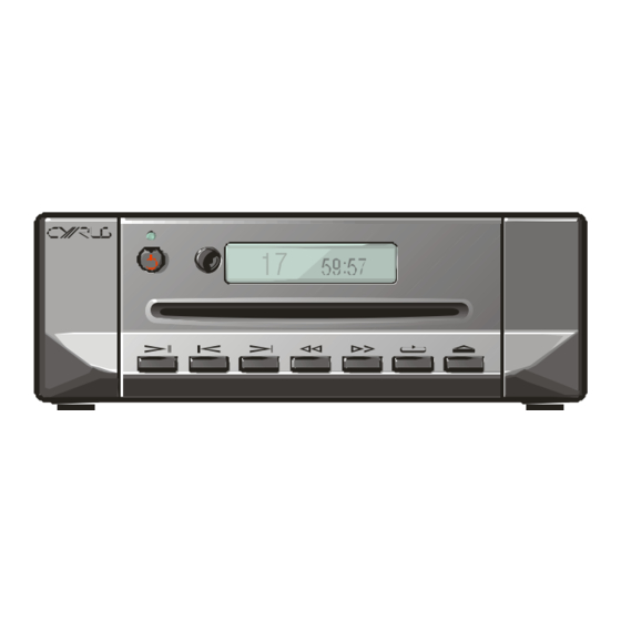
CYRUS CD t
CD PLAYER
SERVICE MANUAL
SPECIFICATIONS
Digital output
Output voltage
Output impedance
Optical output
Sample rate accuracy
Clock jitter
Disc compatibility
Dimensions
(H x W x D)
Weight
ENGINEERED
TO EN TER TA IN
17
59 : 57
Coaxial and Optical SPDIF
500mV pk‐pk
75Ω
Toslink
44.1k ± 50ppm
<80ps
CD Audio, CD‐R
73 x 215 x 360
3.3kg
, 2.8 x 8.4 x14.1
(mm)
(inches)
Advertisement
Table of Contents

Related Manuals for Cyrus CD t


Summary of Contents for Cyrus CD t
-
Page 1: Specifications
ENGINEERED TO EN TER TA IN CYRUS CD t CD PLAYER SERVICE MANUAL 59 : 57 SPECIFICATIONS Digital output Coaxial and Optical SPDIF Output voltage 500mV pk‐pk Output impedance 75Ω Optical output Toslink Sample rate accuracy 44.1k ± 50ppm Clock jitter <80ps Disc compatibility CD Audio, CD‐R ... - Page 2 When tracing signals anywhere on the main PCB exercise caution to keep fingers, tools and test probes etc away from the high voltage power supply section of the PCB. Never use a grounded test probe to test the high voltage (primary) part of the power supply. Ensure that the chassis insulator is correctly fitted under the mains PCB before refitting it into the chassis. © Cyrus Audio Ltd Jun 2014 Cyrus CD t Service Manual Issue 1 ...
- Page 3 SERVICE CAUTIONS The photo below shows the position of caution labels that alert the service technician to the presence of a laser device – On the back panel And on the disc loading mechanism © Cyrus Audio Ltd Jun 2014 Cyrus CD t Service Manual Issue 1 ...
-
Page 4: Table Of Contents
SERVICE MANUAL INDEX INDEX SMD component replacement ..... 2 Type identification ........ 4 Block diagram .......... 5 Technical description ........ 6 Fault finding/disassembly ...... 8 Flash Software ........... 11 MC‐BUS operation ........ 12 Chassis parts drawing/list ...... 13 Front panel parts drawing/list .... 15 Main PCB parts list ........ 16 Servo PCB parts list ........ 21 Circuit diagrams ......... 24 © Cyrus Audio Ltd Jun 2014 1 CD t Service Manual Issue 1 ... -
Page 5: Smd Component Replacement
SMD COMPONENT REPLACEMENT Handling SMD resistors and capacitors are widely used in the Cyrus range of products. When handling SMD components, certain precautions should be observed‐ Handling SMD resistors and capacitors Always store SMD components in their original packaging or in a cool dry environment. Always handle SMD resistors and capacitors with tweezers or a vacuum pencil. Never handle SMD resistors and capacitors with fingers. Hold the SMD component by the body, not by the ends. Do not use SMD resistors or capacitors if the ends are dirty or discoloured. Do not use SMD resistors or capacitors if they have been dropped on the floor‐ they may be internally damaged. Always use replacement components of the correct size and shape. SMD components are available in many different packages. Where possible, order original parts from Cyrus. Handling SMD ICs Always store these components in their original packaging or in a cool dry environment. Always handle SMD transistors and ICs with tweezers or a vacuum pencil. Never handle SMD transistors and ICs with fingers. Ensure that the connection pins of larger multi‐pin ICs are not deformed or damaged ... - Page 6 1. Using fine tipped side cutters or tweezer cutters, snip all the leads of the device and remove the IC body. 2. Desolder the leads from the PCB pads. 3. Clean up the PCB with solder braid. Removing SMD ICs with a hot air SMD tool 1. Fit a suitable size tip for the IC being removed. 2. Heat the IC evenly until the solder melts. 3. Remove the IC with tweezers. Fitting replacement ICs to the PCB with a soldering iron 1. Check that the pins of the IC are not distorted. 2. Using tweezers, position the IC over the footprint. 3. Check that all the IC pins are correctly aligned with the pads. 4. With a very fine tip soldering iron, solder in the pins at the corners of the IC. 5. Re‐check the alignment and correct if necessary. 6. When the alignment is OK, solder the remaining pins of the IC to the PCB. © Cyrus Audio Ltd Jun 2014 3 CD t Service Manual Issue 1 ...
-
Page 7: Type Identification
Type of product Market destination Build number Paint finish (colour) The serial number is on the baseplate. It is therefore important to ensure that a baseplate removed from a product is re‐fitted to the same product. In any communications with Cyrus Service or Quality departments it is essential that the full serial number is quoted so that original specification parts and service information may be supplied. PCB Identification Each PCB is marked with a design revision number and this number should be quoted in all correspondence to the service department when requesting technical advice or requesting ... -
Page 8: Block Diagram
BLOCK DIAGRAM © Cyrus Audio Ltd Jun 2014 5 CD t Service Manual Issue 1 ... -
Page 9: Technical Description
The disc reading laser pickup is mounted in a motor driven slot loader, which receives its operating commands via the servo PCB. The heart of the servo PCB is the CD decoder Integrated Circuit IC401. This is controlled by software running on the main board micro controller IC701 via an I C Bus. The microcontroller sends high level commands (e.g. Read TOC, Play track 1) to the servo PCB via a communication bus. Disc loading is controlled by the microcontroller on the servo PCB. When a disc is inserted into the player the first thing that needs to happen is that the Table of Contents (TOC) of the disc is read. This information contains the start and end location of each track on the disc for disc navigation purposes. In order to read the TOC the laser is switched on by the decoder IC, and a focus ramp is initiated. If focus is found then the disc motor is switched on for a short time, then the PLL is switched on and the disc is accelerated to full speed. Once the speed had been achieved and the PLL is locked onto the data, the radial loop is switched on and the subcode will be read from the disc and fed to the decoder. The focus and radial positions of the laser spot are controlled by the decoder by looking at the diode signals coming from the optical pick up (OPU). These are D1,D2, D3 and D4 for focus, R1 and R2 for radial. The error signal from these diodes is used to generate a PDM signal. This signal is then filtered with a low pass filter and amplified by the motor driver (BA5984FP) to move the actuators. Power for the laser diode is supplied directly from the decoder IC which monitors laser output and adjusts the power accordingly. There is a single system clock on the servo board, 8.4672MHz. This is self‐generated by the decoder IC. There are 2 main power supplies to the servo board, +5V_CD for the signal processing electronics and +5V_MOTOR to IC402 supplying motor and sled power. The +5V_CD supply is sub regulated to +3V3 and sub‐sub‐regulated to +1.8V on‐board for the decoder and other electronics. © Cyrus Audio Ltd Jun 2014 6 CD t Service Manual Issue 1 ... - Page 10 The microcontroller communicates with the decoder on the servo PCB via the CD_CL and CD_DA lines. Digital Outputs The digital audio data from the servo PCB is fed to the main PCB via cable assembly CON701. The data is then buffered by IC601 and IC604. The SPDIF data is fed to the optical output (TOTX401) and to the RCA coaxial output (via digital transformer L402). Power supplies The internal regulated power supplies for the CD t are derived from a switching power supply on the main PCB. This has two separate outputs, +5V and +10V. The 10V supply drives the display backlight via a switchable current source T702/T706/T707. The 5V supply drives the other parts of the circuit. Front panel display The front panel display is a backlit LCD module mounted in a moulding behind the front panel. The LCD module is driven by signals from microcontroller IC701 pins 37 and 38 (DISP_DATA and DISP_SCLK). IC701 also reads back an analogue voltage encoded from keys pressed on the front panel (via KEYS_IN1 pin 7), and remote control information from the eye via line RC5_IN pin 32. © Cyrus Audio Ltd Jun 2014 7 CD t Service Manual Issue 1 ...
-
Page 11: Fault Finding/Disassembly
When the disc reading mechanism or laser pickup are removed from the chassis, it is preferable to fit a flexfoil and use a metal paper clip or similar to bridge all open connections as static protection when handling the pickup. © Cyrus Audio Ltd Jun 2014 8 CD t Service Manual Issue 1 ... - Page 12 First, following the instructions above, remove the loading mechanism. Now disconnect the flexfoil running to the front panel PCB. Finally, the complete front panel assembly including display PCB may now be pressed forward out of the front of the chassis. Remove the fixing © Cyrus Audio Ltd Jun 2014 9 CD t Service Manual Issue 1 ...
- Page 13 FAULT FINDING/DISASSEMBLY screws and the front panel PCB may now be lifted off the front panel assembly. The only part available for service of this PCB is the remote eye. If there are other faults with this PCB it will be necessary to replace the PCB assembly. © Cyrus Audio Ltd Jun 2014 10 CD t Service Manual Issue 1 ...
-
Page 14: Flash Software
6. The Red LED on the main PCB will light to indicate that USB power is available. 7. Release SW702. 8. A new window will pop up on the PC which will show the current firmware.bin file. 9. Delete the existing firmware.bin file. 10. Copy the new firmware.bin file supplied by Cyrus to this folder. 11. Once the file has been copied remove the USB cable. 12. Power up and check the new software version as described above. ... - Page 15 MC‐BUS SYSTEM The MC‐BUS system MC‐BUS is a system which provides communication between the control systems of a number of Cyrus products. The communication takes the form of a serial data stream which is sent from a 'master' product and received and repeated by 'slave' products. The data is thus passed from one product to another around a loop. The master product should then receive the message back which confirms that loop connections have been correctly made. The CD player is a 'slave' product and listens for 'CD' commands from the master product in the loop (usually an amplifier or ...
- Page 16 CHASSIS PARTS DRAWING © Cyrus Audio Ltd Jun 2014 13 CD t Service Manual Issue 1 ...
- Page 17 Ref Part number Description 1 I2‐BACKP/T Rear panel 2 AM‐MTERM/ AC power inlet 3 I2‐CBPOW/080 Power cable 80mm 4 I2‐INSUL/ PCB insulator 5 I6‐CB12W/200 Flex foil cable 12 way 200mm long 6 I2‐LOADR/ASY ASA CD mechanism including servo PCB 7 AM‐COVER/BR Chassis ‐ black AM‐COVER/S1 Chassis ‐ silver 8 I2‐CB25W/170 Flex foil cable 25 way 170mm long I2‐CRADL/ Mechanism mounting cradle SE players 10 I2‐MBSTD/T Main PCB assembly © Cyrus Audio Ltd Jun 2014 14 CD t Service Manual Issue 1 ...
- Page 18 Front Panel parts 1 AM‐POWCP/ Standby knob trim 2 AM‐PLENS/02 Power lens 3 AM‐LENSM/02 Remote eye lens 4 CD‐DISPW/ Display window 5 I6‐MBDIS/02 Display PCB CD‐FACSE/B Front facia black 6 CD‐FACSE/S Front facia silver I2‐FRONT/ Technical Moulding black 7 I2‐FRONT/S Technical Moulding silver 8 I2‐BEZEL/ CD slot trim 9 AM‐BPPLT/V0 Base plate AM‐BFOOT/ Rubber foot © Cyrus Audio Ltd Jun 2014 15 CD t Service Manual Issue 1 ...
-
Page 19: Main Pcb Parts List
120R Ferrite bead R705 SMD0603 47k TF 1/10W 1% R706 SMD0603 47k TF 1/10W 1% R707 SMD0603 47k TF 1/10W 1% R708 SMD0603 47k TF 1/10W 1% R709 SMD0603 47k TF 1/10W 1% R710 SMD0603 Not fitted R711 SMD0603 10R TF 1/10W 1% R712 SMD0603 5R6 TF 1/10W 1% R713 SMD0603 1R0 TF 1/10W 1% © Cyrus Audio Ltd Jun 2014 16 CD t Service Manual Issue 1 ... - Page 20 EL 25V 20% C505 RB.2/.4 1200uF EL 16V 20% C506 CAPSMD6.3 100uF EL 25V 20% C507 CAPSMD6.3 220uF EL 16V 20% C508 RB.2/.2 1uF EL 50V 20% C509 RB.2/.2 1uF EL 50V 20% C510 RAD0.2/RAD0.3 100n CP 630V 10% C511 SMD0603 100n CP 25V 10% C512 SMD0603 100n CP 25V 10% C513 SMD0603 560p CP 50V 5% © Cyrus Audio Ltd Jun 2014 17 CD t Service Manual Issue 1 ...
- Page 21 Not fitted C811 SMD0603 Not fitted C812 SMD0603 Not fitted C813 SMD0603 Not fitted C814 SMD0603 Not fitted C818 SMD0603 22n CP 25V 10% C819 SMD0603 22n CP 25V 10% C820 RAD0.8 100n X CAP X2 250V 20% C823 CAPSMD4.0 Not fitted C824 RB.2/.5 Not fitted C825 CAPSMD4.0 Not fitted C826 CAPSMD4.0 Not fitted © Cyrus Audio Ltd Jun 2014 18 CD t Service Manual Issue 1 ...
- Page 22 T804 SOT‐23 Not fitted T805 SOT‐23 Not fitted FET701 SOT‐23 IRLML6401TRPbF FET702 SOT‐23 Not fitted INTEGRATED CIRCUITS IC401 TSSOP14 CD74HCT14PWR Hex inverter IC402 VSOP24 Not fitted IC501 DIP‐8C TNY377PN SWMPSU driver IC502 SO‐4 SFH6206‐2 Opto coupler IC601 SO‐14 CD74HCT86M Quad XOR IC602 TSSOP20 Not fitted © Cyrus Audio Ltd Jun 2014 19 CD t Service Manual Issue 1 ...
- Page 23 T6612AAAB Single phono SK402 PHONODUAL 12HP070HSG Dual phono SK701 CON‐USB‐67803 651005136421 Mini‐USB connector OTHER PARTS FS801 FUSE_UMZ 3404.2416.11 Miniature fuse T1.0AL RLY801 RELAY_G5NB Not fitted SW701 TACT‐2‐RTANGLE Not fitted SW702 TACT‐2‐RTANGLE KSS321G LFS Tact switch TOTX401 TOX179 GP1FAV51TK0F Optical transmitter TX501 TX‐EF20 094‐931 SMPS TX © Cyrus Audio Ltd Jun 2014 20 CD t Service Manual Issue 1 ...
-
Page 24: Servo Pcb Parts List
100R TF 1/16W 1% R459 SMD0603 Not fitted R460 SMD0603 Not fitted R461 SMD0603 Not fitted R462 SMD0603 Not fitted R463 SMD0603 Not fitted R466 SMD0603 100k TF 1/16W 1% R467 SMD0603 120R BLM18SG121TN1D 0% R468 SMD0603 100k TF 1/16W 1% © Cyrus Audio Ltd Jun 2014 21 CD t Service Manual Issue 1 ... - Page 25 CP 25V 10% C448 SMD0603 100n CP 25V 10% Key: CP = ceramic plate. EL = electrolytic. PE = polyester. PP = polypropylene. BP = bi‐polar. CAPSMD6.3 refers to surface mount device with 6.3mm pitch pads SMD‐0805 refers to surface mount device size code 0805 DIODES D401 LED_5MM TSAL6200 Through Hole IR LED. D402 LED_5MM TSAL6200 Through Hole IR LED. D403 SOD‐123 1N4148W‐V‐GS08 small signal diode D404 SOD‐123 1N4148W‐V‐GS08 small signal diode D405 SOD‐123 1N4148W‐V‐GS08 small signal diode © Cyrus Audio Ltd Jun 2014 22 CD t Service Manual Issue 1 ...
- Page 26 S4B‐PH‐SM4‐ CON402 CON4‐JST‐SMS 4 way SIL header TB(LF)(SN) S3B‐PH‐SM4‐ CON403 CON3‐JST‐SMS 3‐way SIL header TB(LF)(SN) S6B‐PH‐SM4‐ CON404 CON6‐JST‐SMS 6‐way SIL header TB(LF)(SN) CON405 CONZIF25 52271‐2579 25 way ZIF connector SK401 SKT_SMB Not fitted TP414 PAD6.0x6.2 S1951‐46R Spring terminal TP415 PAD6.0x6.2 S1951‐46R Spring terminal © Cyrus Audio Ltd Jun 2014 23 CD t Service Manual Issue 1 ...
-
Page 27: Circuit Diagrams
CIRCUIT DIAGRAMS Circuit diagram index The Cyrus CD t circuit diagrams are listed below. Main PCB Digital output and MC‐BUS .. 25 Power supply ...... 26 Microcontroller ...... 27 Servo PCB Decoder and sled drive.... 28 © Cyrus Audio Ltd Jun 2014 24 CD t Service Manual Issue 1 ... - Page 28 Main PCB schematic diagram Digital output and MC-BUS © Cyrus Audio Ltd Jun 2014 CD t service manual Issue 1...
- Page 29 Main PCB schematic diagram Power supply © Cyrus Audio Ltd Jun 2014 CD t service manual Issue 1...
- Page 30 Main PCB schematic diagram Microcontroller © Cyrus Audio Ltd Jun 2014 CD t service manual Issue 1...
- Page 31 Servo PCB schematic diagram Decoder and sled drive © Cyrus Audio Ltd Jun 2014 CD t service manual Issue 1...
Need help?
Do you have a question about the CD t and is the answer not in the manual?
Questions and answers