
Related Manuals for rada thermotap-3


Summary of Contents for rada thermotap-3
- Page 1 PRODUCT MANUAL IMPORTANT Installer: This Manual is the property of the customer and must be retained with the product for maintenance and operational purposes.
-
Page 2: Table Of Contents
CONTeNTs safety : Warnings ..................3 Advice ....................... 3 Introduction ..................... 4 Description ....................4 Dimensions ....................5 Specification .................... 6 Pressures/Flow Rates ................6 Temperatures ..................7 Connections ..................7 Installation ....................8 General ....................8 Flow Regulator Removal ..............9 Installation .................. -
Page 3: Safety : Warnings
sAFeTY : WARNINGs sAFeTY : WARNINGs The function of this thermostatic mixing tap is to deliver water consistently at a safe temperature. This requires that: It is installed, commissioned, operated and maintained in accordance with the recommendations given in this Manual. For Type 3 installations, valves are only to be used for applications covered by their approved designations, refer to section: ‘Type 3 Valves’. -
Page 4: Introduction
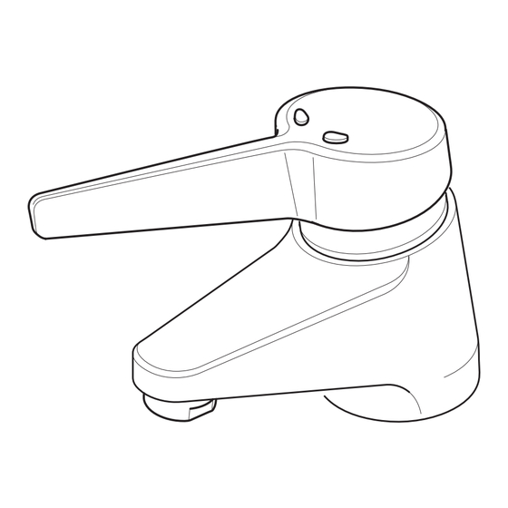
‘Type 3 Valves’. DesCRIPTION The Rada Thermotap-3 is a lever operated sequential mixing tap for basins employing a temperature sensor to provide water at safe, constant temperatures for handwashing. It is suitable for use with single hole basins with hole sizes of between 26 - 36 mm diameter. -
Page 5: Dimensions
DIMeNsIONs All Dimensions and Angles are Approximate. Short Lever 100 mm Long Lever 150 mm Ø 26 - 36 mm 110 mm Max 30 mm 180° Flexible Tails Rigid Tails (15 mm Compression Fitting/1/2" BSP Male) -
Page 6: Specification
sPeCIFICATION Normal Operating Conditions are considered as: • inlet dynamic pressures nominally balanced to within 10% of each other during flow • a differential of approximately 50°C between the hot and cold inlet temperatures, and with differentials of 15 - 35°C between the blend setting and either supply • daily usage of 1-6 hours •... -
Page 7: Temperatures
Recommended Minimum Cold Water supply Temperature: 5°C. Recommended Maximum Hot Water supply Temperature: 65°C. Note! The Thermotap-3 can accept temporary temperature excursions up to 85°C without damage, however operation at such elevated supply temperatures is not recommended. For reasons of general safety, hot water storage temperatures should ideally be maintained at between 60 - 65°C where serving ablutionary... -
Page 8: Installation
Supply pipework layout should be arranged to minimise the effect of hydraulic restriction or other outlet usage upon the dynamic pressures at the Thermotap-3 inlets. Recommended minimum supply line pipe diameter is 8 mm. For Dynamic supply Pressures below 0.4 bar we recommend removal of the flow regulators to allow increased flow. -
Page 9: Flow Regulator Removal
Flow Regulator Removal Note! This procedure is only necessary when the dynamic supply pressure is below 0.4 bar. Isolate the hot and cold supplies with the isolating valves. Checkvalve Disconnect the flexible hoses or Assembly rigid inlet tails as applicable, by unscrewing the union nuts. -
Page 10: Installation
Installation Screw the fixing studs fully into the Thermotap-3 body. Place the 'O' seal in the groove in the base of the Thermotap-3 'O' Seal body. Place either rigid or flexible inlet Fixing Studs tail through one of the larger holes in the backplate, orientate the 26 to 36 mm backplate to suit the hole size in Diameter the basin. -
Page 11: Commissioning
Note! For Type 3 valves in healthcare installations the maximum blend temperature is determined by the application, refer to section: ‘Type 3 Valves, Application’. The Rada Thermotap-3 is fully performance tested, and the maximum temperature is preset to approximately 41°C under ideal installation conditions at the factory. -
Page 12: Flow Shut Off Setting
Flow shut Off setting Fully open the inlet isolation valves. Remove the lever using the 2.5 mm A/F hexagonal wrench, and remove the stop ring. Refit the lever to the spindle (position not important) and open the tap. Turn the lever to the off position so the flow just stops, then rotate a further 10 - 20 degrees, to make sure of a tight shut off. Remove the lever and refit the stop ring with the arrow aligned with the tap spout (refer to illustration). Fit the lever to the spindle in the OFF position (parallel to the wall) and make sure that the lever engages with the stop, i.e. cannot be turned clockwise (refer to illustration). -
Page 13: Maximum Temperature Setting
Maximum Temperature setting Make sure that an adequate supply of hot water is available at the hot inlet of the Thermotap-3. The minimum temperature of the hot water must be at least 10°C above the desired blend, however during resetting this should be close to the typical storage maximum to offset the possibility of any blend shift due to fluctuating supply temperatures. -
Page 14: Operation
OPeRATION The Rada Thermotap-3 has a single lever that provides sequential operation from OFF through COLD and WARM to a preset maximum blend temperature. The maximum temperature is preset to approximately 41°C under ideal installation conditions at the factory. To change this setting refer to the information given in section: Commissioning'. -
Page 15: Fault Diagnosis
Inlet supplies reversed (hot supply to cold inlet). c o l d w a t e r Check. from outlet. No hot water reaching Thermotap-3. Check. Check strainers and inlet/outlet fittings for blockage. Refer symptom 5. below. Installation conditions continuously outside operating parameters: refer to section: 'Specifications', and 2.e. - Page 16 symptom Cause/Rectification M a x i m u m Indicates incorrect maximum temperature setting; refer b l e n d to COMMIssIONING. temperature As symptom 4. above. setting too As symptom 5. above. h o t o r t o o cool.
-
Page 17: Maintenance
To ensure your Rada/Mira products function correctly and give continued safe performance Service Contracts can be undertaken (subject to site survey). All Service Contract work is carried out by fully trained Rada/Mira Service Engineers who carry a comprehensive range of genuine spare parts. For details on arranging a Service Contract please contact Aftersales/Service. - Page 18 Plug Grubscrew Grub Screw Rising Spindle Stop Ring 'O' Seal (Rising Spindle) Collar 'O' Seal (Cold 'O' Seal Seat) (Follower) Follower Circlip Shuttle/Thermostat Assembly (Includes Overload Spring) Head Return Spring Screw Retainer 'O' Seal (Head) Thrust Washer 'O' Seal (Separator) Non-rising Spindle Hot Seat ...
- Page 19 Do not remove the 'O' seal in the bottom face of the rising spindle at this stage (refer to paragraph 15). This 'O' seal forms the cold seat for the Thermotap-3 and the groove is swaged to hold it in position. 11. Withdraw the shuttle/thermostat assembly, complete with return spring, from the Thermotap-3 body.
- Page 20 Thermotap-3 body correctly, and install the retainer. Grease the 'O' seal. 25. Locate the spring on the retainer, and install the shuttle/thermostat assembly. 26. Carefully screw the head assembly, complete with 'O' seal into the Thermotap-3 body. Use a suitable spanner to tighten the head assembly fully.
- Page 21 Maintenance Procedure - Checkvalves & strainers Refer to illustrations in section: 'Installation'. Hot water entering the cold supply, or vice versa, indicates that immediate attention is required. This is performed by removing and cleaning, or renewing the checkvalve assemblies as necessary. Blockage of the strainer screens can lead to poor flow performance and reduced temperature control. It is essential that the strainer screens are cleaned or, if necessary renewed, as part of the six-monthly maintenance operations.
-
Page 22: Type 3 Valves
Application The approved designations for Type 3 Valves are as follows: Model Designation Code Rada Thermotap-3 HP-WE, LP-WE supply Conditions For applications where a Type 3 Valve is required, the supply conditions must comply with the values extracted from the TMV3 standard, shown in the table below. Note that both hot and cold supply pressures must lie within the same pressure range. - Page 23 Commissioning Purpose Since the installed supply conditions are likely to be different from those applied in the laboratory tests it is appropriate, at commissioning, to carry out some simple checks and tests on each mixing valve to provide a performance reference point for future in-service tests.
-
Page 24: In Service Testing
In service Testing Purpose The purpose of in-service tests is to regularly monitor and record the performance of the thermostatic mixing valve. Deterioration in performance can indicate the need for service work on the valve and/or water supplies. Procedure Using the same measuring equipment or equipment to the same specification as used in the commissioning of the valve, adjust the temperature of the mixed water in accordance with the instructions in section: ‘Operation’... - Page 25 Note! In-service tests should be carried out with a frequency, which identifies a need for service work before an unsafe water temperature can result. Frequency of In-service Tests Healthcare The In-Service Test Procedure must be followed 6 to 8 weeks after commissioning and 12 to 15 weeks after commissioning. The recorded mixed water temperature from these two tests will determine the maximum frequency for future service intervals. Result of 6-8 week tests Result of 12-15 week tests Next service interval...
-
Page 26: Spare Parts
sPARe PARTs 066.66 Flow Regulator 455.01 Short Lever Assembly 455.02 Long Lever Assembly 455.04 Flexible Tail - Cold 455.05 Flexible Tail - Hot 455.07 Aerator 455.10 Checkvalve Assembly (single) 916.59 Flow Straightener 925.72 Shuttle/Thermostat Assembly 928.49 Head Assembly 936.13 Fixing Kit 936.23 Service Pack (components identified *) 1555.063 Rigid Tails (pair) - Page 27 455.01 455.02 925.72 455.07 916.59 936.13 Rigid Tails 1555.063 928.49 Flexible Tails 455.04 455.05 455.10 066.66...
-
Page 28: Customer Care
CusTOMeR CARe 1058907-W2-D (H72A, H72B) (1555) © Kohler Mira Limited, March 2009...
Need help?
Do you have a question about the thermotap-3 and is the answer not in the manual?
Questions and answers