
Related Manuals for ProSoft Technology PLX82-EIP-PNC


Summary of Contents for ProSoft Technology PLX82-EIP-PNC
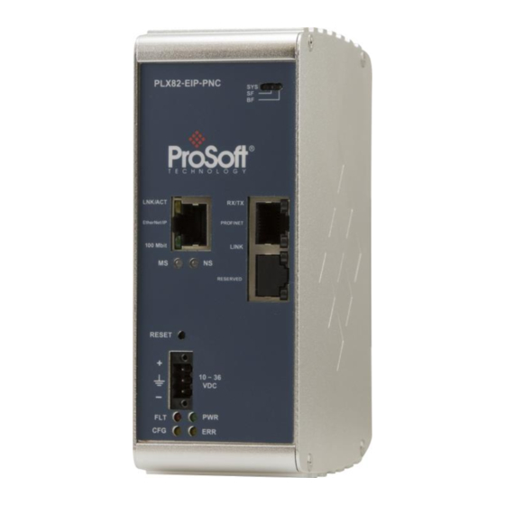
- Page 1 PLX82-EIP-PNC Communication Gateway EtherNet/IP™ Server to PROFINET Controller July 24, 2018 USER MANUAL...
-
Page 2: Your Feedback Please
Neither ProSoft Technology nor any of its affiliates or subsidiaries shall be responsible or liable for misuse of the information contained herein. Information in this document including illustrations, specifications and dimensions may contain technical inaccuracies or typographical errors. -
Page 3: Important Safety Information
Important Safety Information Power, Input, and Output (I/O) wiring must be in accordance with Class I, Division 2 wiring methods, Article 501-4 (b) of the National Electrical Code, NFPA 70 for installation in the U.S., or as specified in Section 18-1J2 of the Canadian Electrical Code for installations in Canada, and in accordance with the authority having jurisdiction. -
Page 5: Table Of Contents
Setting a Temporary IP Address ................19 Ethernet Configuration .................... 22 Saving the Project ....................23 Downloading the Configuration File to the PLX82-EIP-PNC ........24 Uploading a Configuration from the PLX82-EIP-PNC ..........25 Exporting a Project ....................26 Writing the Project to Compact Flash ..............27 Configuring the EtherNet/IP Driver RSLogix 5000 ...................... - Page 6 PNC Status Data in Upper Memory ..............142 Reference 10.1 EtherNet/IP Explicit Messaging Server Command Support ......... 145 10.2 Accessing the PLX82-EIP-PNC Internal Memory ..........146 10.2.1 MSG Instruction Type - CIP .................. 146 10.2.2 MSG Instruction Type - PCCC ................147 10.3...
- Page 7 PLX82-EIP-PNC ♦ Communication Gateway Contents EtherNet/IP™ Server to PROFINET Controller User Manual Support, Service & Warranty 11.1 Contacting Technical Support ................149 11.2 Warranty Information ..................... 151 Index ProSoft Technology, Inc. Page 7 of 154 July 24, 2018...
- Page 8 Contents PLX82-EIP-PNC ♦ Communication Gateway User Manual EtherNet/IP™ Server to PROFINET Controller Page 8 of 154 ProSoft Technology, Inc. July 24, 2018...
-
Page 9: Start Here
36 PROFINET RT devices such as field I/O, drives, HMIs, controllers, etc. The PLX82-EIP-PNC gateways are stand-alone DIN-rail mounted units that provide two Ethernet ports for communications, remote configuration, and diagnostics. The onboard SD card slot (SD card optional) is used for storing configuration files that can be used for recovery, transferring the configuration to another gateway, or general configuration backup. - Page 10 Start Here PLX82-EIP-PNC ♦ Communication Gateway User Manual EtherNet/IP™ Server to PROFINET Controller The module is configured using ProSoft Configuration Builder (PCB) and ProSoft fdt Configuration Manager. ODVA Approved PROFINET v2 certification with PROFINET Class A compliance ...
-
Page 11: System Requirements
PROFINET Controller Screwdriver HRD250 Small, flat-bladed screwdriver Power Connector J180 3-wire DC power connector If any of these components are missing, please contact ProSoft Technology Technical Support for replacement parts. ProSoft Technology, Inc. Page 11 of 154 July 24, 2018... -
Page 12: Setting Jumpers
EtherNet/IP™ Server to PROFINET Controller Setting Jumpers The jumper settings are located on the back of the PLX82-EIP-PNC. For security reasons, the Mode 1 and Mode 2 jumpers are not readily accessible. Under normal conditions, these two jumpers will not be required. -
Page 13: Connecting Power
User Manual Connecting Power Use the J180 Power Connector to connect to the proper signals. WARNING: Be sure not to reverse polarity when applying power to the PLX82-EIP-PNC. This causes permanent damage to the internal power distribution circuits. ProSoft Technology, Inc. - Page 14 PLX82-EIP-PNC ♦ Communication Gateway User Manual EtherNet/IP™ Server to PROFINET Controller Page 14 of 154 ProSoft Technology, Inc. July 24, 2018...
-
Page 15: Prosoft Configuration Builder Software
Writing the Project to Compact Flash ............ 27 ProSoft Configuration Builder (PCB) and ProSoft fdt Configuration Manager is used to configure the PLX82-EIP-PNC. You can find both software files at www.prosoft-technology.com. Important Note: Microsoft .NET must be installed on your PC or laptop used to perform configuration tasks. -
Page 16: Creating A New Project
ProSoft Configuration Builder Software PLX82-EIP-PNC ♦ Communication Gateway User Manual EtherNet/IP™ Server to PROFINET Controller Creating a New Project From your PC, click S > P > P TART ECHNOLOGY ONFIGURATION UILDER Click F > N . The application prompts for a Module Type. - Page 17 ProSoft Configuration Builder Software EtherNet/IP™ Server to PROFINET Controller User Manual Select the PLX80 radio button and then select PLX82-EIP-PNC. Click OK. The PLX82-EIP-PNC is now added to ProSoft Configuration builder. ProSoft Technology, Inc. Page 17 of 154 July 24, 2018...
-
Page 18: Setting A Project Name
ProSoft Configuration Builder Software PLX82-EIP-PNC ♦ Communication Gateway User Manual EtherNet/IP™ Server to PROFINET Controller Setting a Project Name The project name is initially set to "Default Location". Right click on the D icon and select R EFAULT OCATION ENAME... -
Page 19: Setting A Temporary Ip Address
To use PDS, arrange the Ethernet connection so that there is no router or layer 3 switch between the computer and the PLX82-EIP-PNC, or reconfigure the router or layer 3 switch to allow the routing of the UDP broadcast messages. - Page 20 ProSoft Configuration Builder Software PLX82-EIP-PNC ♦ Communication Gateway User Manual EtherNet/IP™ Server to PROFINET Controller When the Connection Setup dialog opens, click the B button ROWSE EVICES to locate your device. This launches Prosoft Discovery Service, which displays the ProSoft modules...
- Page 21 PLX82-EIP-PNC ♦ Communication Gateway ProSoft Configuration Builder Software EtherNet/IP™ Server to PROFINET Controller User Manual Right-click the module, and then click A SSIGN EMPORARY The module’s default IP address is 192.168.0.250. Enter an unused IP within your subnet, and then click OK.
-
Page 22: Ethernet Configuration
Ethernet Configuration This is used to provide address information for the gateway; in this case, the EIP driver. This is unique address information for the PLX82-EIP-PNC's EIP driver and diagnostic interface. The default is initially set to 192.168.0.250. Page 22 of 154 ProSoft Technology, Inc. -
Page 23: Saving The Project
PLX82-EIP-PNC ♦ Communication Gateway ProSoft Configuration Builder Software EtherNet/IP™ Server to PROFINET Controller User Manual Select my_ip and enter the IP address of the EIP device in the gateway. Select netmask and enter the network mask. If using a gateway/router, select gateway and enter the IP address of the network gateway (router). -
Page 24: Downloading The Configuration File To The Plx82-Eip-Pnc
Manager, and the software displays the following message: "Successfully connected." If the PLX82-EIP-PNC’s IP address does not match what was entered in ProSoft Configuration Builder, then the software displays an error message: "Error: Connecting to Module. Please check your IP Address."... -
Page 25: Uploading A Configuration From The Plx82-Eip-Pnc
You want to back up the configuration for safety. Warning: This function replaces the current configuration in the ProSoft Configuration Builder with the one from the PLX82-EIP-PNC. Make sure you save the current configuration before uploading the configuration from the PLX82-EIP-PNC. -
Page 26: Exporting A Project
) button. This launches the ProSoft Discovery Service ROWSE EVICE application. Enter the IP address of the PLX82-EIP-PNC. All PLX82-EIP-PNC's are shipped with a default IP address 192.168.0.250. Click the U EFAULT button to use the default address. Use the T button to ensure that the connection is good. -
Page 27: Writing The Project To Compact Flash
PLX82-EIP-PNC ♦ Communication Gateway ProSoft Configuration Builder Software EtherNet/IP™ Server to PROFINET Controller User Manual Writing the Project to Compact Flash This procedure describes how to save a project from a PC to a Compact Flash drive. From PCB, navigate to P >... - Page 28 ProSoft Configuration Builder Software PLX82-EIP-PNC ♦ Communication Gateway User Manual EtherNet/IP™ Server to PROFINET Controller Page 28 of 154 ProSoft Technology, Inc. July 24, 2018...
-
Page 29: Configuring The Ethernet/Ip Driver
In This Chapter RSLogix 5000 ..................30 Adding an Ethernet Bridge ..............31 Adding the PLX82-EIP-PNC ..............33 Importing the Ladder Rung ..............36 Downloading the RSLogix 5000 Project to the Processor ..... 38 ... -
Page 30: Rslogix 5000
PLX82-EIP-PNC ♦ Communication Gateway User Manual EtherNet/IP™ Server to PROFINET Controller RSLogix 5000 If you want to add the PLX82-EIP-PNC gateway to an existing project, skip to Adding an Ethernet Bridge (page 31). To create a new project... In RSLogix 5000, choose F >... -
Page 31: Adding An Ethernet Bridge
PLX82-EIP-PNC ♦ Communication Gateway Configuring the EtherNet/IP Driver EtherNet/IP™ Server to PROFINET Controller User Manual Adding an Ethernet Bridge Expand the I/O C folder in the Project tree. Right-click the ONFIGURATION appropriate communications bus and choose N ODULE This opens the Select Module Type dialog box. - Page 32 Configuring the EtherNet/IP Driver PLX82-EIP-PNC ♦ Communication Gateway User Manual EtherNet/IP™ Server to PROFINET Controller For this example, click the 1756-ENBT E and then click THERNET RIDGE REATE Enter the name, revision, and IP address for the 1756-ENBT and then click Page 32 of 154 ProSoft Technology, Inc.
-
Page 33: Adding The Plx82-Eip-Pnc
PLX82-EIP-PNC ♦ Communication Gateway Configuring the EtherNet/IP Driver EtherNet/IP™ Server to PROFINET Controller User Manual Adding the PLX82-EIP-PNC In RSLogix 5000, under the 1756-ENBT icon, right-click E and then THERNET choose N ODULE Select the G /IP CIP B and then click C... - Page 34 Configuring the EtherNet/IP Driver PLX82-EIP-PNC ♦ Communication Gateway User Manual EtherNet/IP™ Server to PROFINET Controller Enter the name and IP address for the gateway and then click OK. Under the gateway (PLX82_EIP_PNC in this example), right-click CIP B and then choose N...
- Page 35 PLX82-EIP-PNC ♦ Communication Gateway Configuring the EtherNet/IP Driver EtherNet/IP™ Server to PROFINET Controller User Manual Add a Class 1 connection (enter the name and configuration parameters). Enter the Name, select D -INT for Comm Format, and enter the Connection Parameters as shown below. Click OK.
-
Page 36: Importing The Ladder Rung
Configuring the EtherNet/IP Driver PLX82-EIP-PNC ♦ Communication Gateway User Manual EtherNet/IP™ Server to PROFINET Controller Importing the Ladder Rung Download the .L5X file from the PLX82-EIP-PNC product page at www.prosoft-technology.com. Open the Main Routine. Right-click on an existing rung and select I MPORT UNGS At the Input Rungs dialog, locate the directory that contains the Add On rung. - Page 37 PLX82-EIP-PNC ♦ Communication Gateway Configuring the EtherNet/IP Driver EtherNet/IP™ Server to PROFINET Controller User Manual In the Import Configuration dialog box, make sure the Operation is set to , and then click OK. REATE When the import completes, the Add-On Instruction appears under Add-On Instructions in the window.
-
Page 38: Downloading The Rslogix 5000 Project To The Processor
EQUESTED ACKET NTERVAL Check the PLX82-EIP-PNC's IP address. This is located in the bottom left of the Diagnostics page. If errors persist, download the configuration again to make sure that the module configuration matches the configured RSLogix 5000 program. -
Page 39: Eip Class 3 Server Connection
PLX82-EIP-PNC ♦ Communication Gateway Configuring the EtherNet/IP Driver EtherNet/IP™ Server to PROFINET Controller User Manual EIP Class 3 Server Connection Use the EIP Class 3 Server connection in ProSoft Configuration Builder when the gateway is acting as a server (slave) device responding to message instructions initiated from a client (Controller) device such as an HMI, DCS, PLC, or PAC. -
Page 40: Eip Class 1 Connection
RSLogix 5000 v2.0 or higher can take advantage of premier integration with an Add-on profile. After you create the PLX82-EIP-PNC in RSLogix 5000, you must configure gateway connections. In ProSoft Configuration Builder, click the [+] next to the gateway, and then click the [+] next to EIP Class 1 Connection [x]. -
Page 41: Eip Class 3 Client/Uclient [X] Connection
PLX82-EIP-PNC ♦ Communication Gateway Configuring the EtherNet/IP Driver EtherNet/IP™ Server to PROFINET Controller User Manual Parameter Value Description Input Data Address 0 to 9999 This parameter specifies the starting address within the gateway's virtual database for data transferred from the PLC to the module. -
Page 42: Eip Class 3 Client/Uclient [X] Commands
Configuring the EtherNet/IP Driver PLX82-EIP-PNC ♦ Communication Gateway User Manual EtherNet/IP™ Server to PROFINET Controller The following table specifies the configuration for the EIP client (Controller) device on the network port: Parameter Value Description Minimum Command 0 to 65535 Specifies the number of milliseconds to wait between the initial... - Page 43 PLX82-EIP-PNC ♦ Communication Gateway Configuring the EtherNet/IP Driver EtherNet/IP™ Server to PROFINET Controller User Manual Class 3 Client/UClient [x] Commands SLC500 2 Address Fields Parameter Value Description Enable Enable Specifies if the command should be executed and under what conditions.
- Page 44 Configuring the EtherNet/IP Driver PLX82-EIP-PNC ♦ Communication Gateway User Manual EtherNet/IP™ Server to PROFINET Controller Class 3 Client/UClient [x] Commands SLC500 3 Address Fields Parameter Value Description Enable Enable Specifies if the command should be executed and under what conditions.
- Page 45 PLX82-EIP-PNC ♦ Communication Gateway Configuring the EtherNet/IP Driver EtherNet/IP™ Server to PROFINET Controller User Manual Class 3 Client/UClient [x] Commands PLC5 Binary Parameter Value Description Enable Enable Specifies if the command should be executed and under what conditions. Disable Enable - The command is executed each scan of the command list.
- Page 46 Configuring the EtherNet/IP Driver PLX82-EIP-PNC ♦ Communication Gateway User Manual EtherNet/IP™ Server to PROFINET Controller Class 3 Client/UClient [x] Commands PLC5 ASCII Parameter Value Description Enable Enable Specifies if the command should be executed and under what conditions. Disable - The Command is executed each scan of the command list...
- Page 47 PLX82-EIP-PNC ♦ Communication Gateway Configuring the EtherNet/IP Driver EtherNet/IP™ Server to PROFINET Controller User Manual Class 3 Client/UClient [x] Commands Controller Tag Access Parameter Value Description Enable Enable Specifies if the command should be executed and under what conditions. Disable...
- Page 48 Configuring the EtherNet/IP Driver PLX82-EIP-PNC ♦ Communication Gateway User Manual EtherNet/IP™ Server to PROFINET Controller Class 3 Client/UClient [x] Commands Basic Parameter Value Description Enable Enable Specifies if the command should be executed and under what conditions. Disable - The command is executed each scan of the command list...
-
Page 49: Configuring The Eip Processor Path
PLX82-EIP-PNC ♦ Communication Gateway Configuring the EtherNet/IP Driver EtherNet/IP™ Server to PROFINET Controller User Manual Configuring the EIP Processor Path The EIP Processor Path parameter allows you to set or change the IP address of a device being addressed by a command. For example, a PLC. Settings here specify the information required to identify where alarms are to be sent. - Page 50 Configuring the EtherNet/IP Driver PLX82-EIP-PNC ♦ Communication Gateway User Manual EtherNet/IP™ Server to PROFINET Controller To edit the EIP Processor path, expand the EIP Processor Path selection and click on PLX82-EIP-PNC > EIP P > EIP P ROCESSOR ROCESSOR Parameter...
-
Page 51: Configuring The Profinet Controller
Technology is in the process of adding limitations to the configuration software, and until then, we have produced a guideline document to aid in the proper configuration of the PROFINET controller. This guideline is available from the ProSoft website, accessible from the PLX82-EIP-PNC product page. The file is named "ProSoft-PROFINET-Net-Load-Calculator+v4.xlsx. - Page 52 Configuring the PROFINET Controller PLX82-EIP-PNC ♦ Communication Gateway User Manual EtherNet/IP™ Server to PROFINET Controller From the PCB window, double-click on the PROFINET icon. This opens the ProSoft fdt Configuration Manager network view. Note: If you have not already saved the project file, you are prompted to do so before you can proceed.
- Page 53 PLX82-EIP-PNC ♦ Communication Gateway Configuring the PROFINET Controller EtherNet/IP™ Server to PROFINET Controller User Manual Double-click on the PLX82-EIP-PNC icon. This opens the Controller Network Settings window. Click on C located in the Navigation Area ONTROLLER ETWORK ETTINGS pane of the netDevice Configuration window.
-
Page 54: Importing Gsd Files
EtherNet/IP™ Server to PROFINET Controller Importing GSD Files PROFINET Device information files (typically GSD or GSDML) must be imported for all devices you intend to connect to through the PLX82-EIP-PNC. GSD and GSDML files are available from the PROFINET device manufacturer. Important: - For devices with GSDML XML Schema version 1.0, every module has one submodule assigned. - Page 55 PLX82-EIP-PNC ♦ Communication Gateway Configuring the PROFINET Controller EtherNet/IP™ Server to PROFINET Controller User Manual Click O and then click Y . The GSD file is displayed in the right pane. Open the device folder to display the device icon(s).
-
Page 56: Adding A Slave Device To The Project
Configuring the PROFINET Controller PLX82-EIP-PNC ♦ Communication Gateway User Manual EtherNet/IP™ Server to PROFINET Controller Adding a Slave Device to the Project Locate the slave from the Slave Catalog. Drag and drop the slave onto the PROFINET bus line. If you are installing multiple slave devices, perform the same steps to add them to the network. -
Page 57: Configuring A Slave Device
This procedure configures all PROFINET slave devices for the PNC. As slaves are configured, configuration information is automatically placed in the PLX82- EIP-PNC. This information is visible by double-clicking on the PLX82-EIP-PNC icon. Note: The diagram only shows one slave device. All slaves on the network must be defined and configured according to the following steps: Double-click on the slave device. - Page 58 Configuring the PROFINET Controller PLX82-EIP-PNC ♦ Communication Gateway User Manual EtherNet/IP™ Server to PROFINET Controller When complete, click A and then click OK. PPLY Page 58 of 154 ProSoft Technology, Inc. July 24, 2018...
-
Page 59: Verifying Slave Device Information
Verifying Slave Device Information Slave devices are automatically configured. As configured, the new information is immediately visible in the module. To view device information, double-click on the PLX82-EIP-PNC module icon and then select the appropriate link. ProSoft Technology, Inc. Page 59 of 154... -
Page 60: Controller Network Settings
Configuring the PROFINET Controller PLX82-EIP-PNC ♦ Communication Gateway User Manual EtherNet/IP™ Server to PROFINET Controller 4.4.1 Controller Network Settings Controller Network Settings display the following information: Name of Station Description of the station IP Address, Network Mask, and Gateway Address... -
Page 61: Device Table
PLX82-EIP-PNC ♦ Communication Gateway Configuring the PROFINET Controller EtherNet/IP™ Server to PROFINET Controller User Manual 4.4.2 Device Table The Device Table lists all devices connected and configured in the PROFINET Controller. Parameter Description Activate Use this checkbox to activate or deactivate a station Index This is editable. - Page 62 Configuring the PROFINET Controller PLX82-EIP-PNC ♦ Communication Gateway User Manual EtherNet/IP™ Server to PROFINET Controller To change the Index number... Click on the I number to be changed. NDEX Edit the Index number. Click OK when done. To change the name of the station...
-
Page 63: Ip Address Table
The IP Address Table shows the IP address of each connected slave device. The IP address is assigned automatically based on incrementing the last octet based on the IP address of the PLX82-EIP-PNC. For example, if the controller IP address is 192.168.0.240, the first device added will have an IP address of 192.168.0.241. -
Page 64: Process Data
Configuring the PROFINET Controller PLX82-EIP-PNC ♦ Communication Gateway User Manual EtherNet/IP™ Server to PROFINET Controller 4.4.4 Process Data The Process Data table serves as an external process data interface (for data transfer to a PLC unit). It lists the devices connected to the controller, and well as configured modules or input or output signals of the devices. -
Page 65: Address Table
PLX82-EIP-PNC ♦ Communication Gateway Configuring the PROFINET Controller EtherNet/IP™ Server to PROFINET Controller User Manual 4.4.5 Address Table The Address Table displays a list of all addresses used in the process data image. The displayed addresses refer to the PROFINET Controller (PNC). This page allows you to view current input and output data sizes per slave device. - Page 66 Configuring the PROFINET Controller PLX82-EIP-PNC ♦ Communication Gateway User Manual EtherNet/IP™ Server to PROFINET Controller CSV Export This option allows you to export input and output addresses as a .CSV file (comma separated values). Click the CSV E button. The File Save dialog opens.
- Page 67 PLX82-EIP-PNC ♦ Communication Gateway Configuring the PROFINET Controller EtherNet/IP™ Server to PROFINET Controller User Manual Parameter Description Name of Station Symbolic name of the assigned slave device. Module Name of the module according to the GSD or GSDML file. Submodule Displays submodule information.
-
Page 68: Fsu-/Port-Settings
Configuring the PROFINET Controller PLX82-EIP-PNC ♦ Communication Gateway User Manual EtherNet/IP™ Server to PROFINET Controller 4.4.6 FSU-/Port-Settings The Fast Start Up (FSU) Port Settings pane is used to specify devices that must use a fast start up connection to establish the cyclic data exchange. Check with your device manufacturer to determine if your device must use FSU. -
Page 69: Stations Timing
PLX82-EIP-PNC ♦ Communication Gateway Configuring the PROFINET Controller EtherNet/IP™ Server to PROFINET Controller User Manual Parameter Description Name The symbolic name of the PROFINET slave device. Name of Station This is the network name of the slave device. The name of the device is set in the Device Table. -
Page 70: Controller Settings
Configuring the PROFINET Controller PLX82-EIP-PNC ♦ Communication Gateway User Manual EtherNet/IP™ Server to PROFINET Controller 4.4.8 Controller Settings The Controller Settings pane allows you to control the behavior of the PNC controller. Page 70 of 154 ProSoft Technology, Inc. July 24, 2018... - Page 71 PLX82-EIP-PNC ♦ Communication Gateway Configuring the PROFINET Controller EtherNet/IP™ Server to PROFINET Controller User Manual Parameter Description Start of bus Automatically by device or Controlled by application. communication If Automatically by device, the PNC controller device starts with the data exchange on the bus after initialization has ended.
-
Page 72: Ethernet Devices
Configuring the PROFINET Controller PLX82-EIP-PNC ♦ Communication Gateway User Manual EtherNet/IP™ Server to PROFINET Controller 4.4.9 Ethernet Devices The Ethernet Devices pane provides a view of all slave devices on the network after performing a search. It also allows you to edit each device. The device name must match the Name of Station field. - Page 73 PLX82-EIP-PNC ♦ Communication Gateway Configuring the PROFINET Controller EtherNet/IP™ Server to PROFINET Controller User Manual Click the S button to start the search. EARCH EVICES The current online devices appear in the grid. ProSoft Technology, Inc. Page 73 of 154...
- Page 74 Configuring the PROFINET Controller PLX82-EIP-PNC ♦ Communication Gateway User Manual EtherNet/IP™ Server to PROFINET Controller Parameter Description MAC Address Unique address of the device set by the device manufacturer. Device Type Name given to the device that provides a description of the device.
- Page 75 PLX82-EIP-PNC ♦ Communication Gateway Configuring the PROFINET Controller EtherNet/IP™ Server to PROFINET Controller User Manual Creating New, or Using Existing Configuration Information The lower area of the Ethernet Devices pane allows you to change information returned by the search. Note: If you are going to use a configuration from a different device, use the "Use Configuration of"...
- Page 76 Configuring the PROFINET Controller PLX82-EIP-PNC ♦ Communication Gateway User Manual EtherNet/IP™ Server to PROFINET Controller *Set Name (new configurations) Enter the new device name and click the S button. If you are changing the name of the PROFINET controller, the name must match the name specified in the Controller Network Settings page.
- Page 77 PLX82-EIP-PNC ♦ Communication Gateway Configuring the PROFINET Controller EtherNet/IP™ Server to PROFINET Controller User Manual *Set IP Address (new configurations) Enter the IP address, Subnet mask, and Gateway address of this device and then click the S button. DDRESS You can also obtain an IP address via DHCP by checking the Get IP Address via DHCP radio button.
-
Page 78: Viewing Configured Device Information
Configuring the PROFINET Controller PLX82-EIP-PNC ♦ Communication Gateway User Manual EtherNet/IP™ Server to PROFINET Controller 4.4.10 Viewing Configured Device Information Device Info The Device Info pane displays manufacturer information about the device, which is defined in the GSDML file. Page 78 of 154 ProSoft Technology, Inc. - Page 79 PLX82-EIP-PNC ♦ Communication Gateway Configuring the PROFINET Controller EtherNet/IP™ Server to PROFINET Controller User Manual Name Value Main family Attribute of the GSDML family element. It contains the assignment of the device to a function class. One of the following values are allowed: ...
- Page 80 Configuring the PROFINET Controller PLX82-EIP-PNC ♦ Communication Gateway User Manual EtherNet/IP™ Server to PROFINET Controller Module Info The S drop-down list of the Module Info pane displays all available ELECT ODULE modules described in the GSDML file. Name Value Vendor ID...
-
Page 81: Profinet Start Input And Output Byte Offsets
Offsets The PNC option in PCB allows you to set the PROFINET Start Input Byte Offset and Start Output Byte Offset values within PLX82-EIP-PNC internal memory. You can also use this area to configure floating point or other multi-register values. - Page 82 PROFINET Start Input and Output Byte Offsets PLX82-EIP-PNC ♦ Communication Gateway User Manual EtherNet/IP™ Server to PROFINET Controller Parameter Description Start Input Byte Offset Byte offset for input data Start Output Byte Offset Byte offset for output data Swap Read Input Data Bytes...
-
Page 83: Acyclic Data
PLX82-EIP-PNC ♦ Communication Gateway Acyclic Data EtherNet/IP™ Server to PROFINET Controller User Manual Acyclic Data If you have a module that supports acyclic messaging and wish to use it, you must configure RSLogix 5000 to handle this. EIP requires a Class 3 function from the PLC. - Page 84 Acyclic Data PLX82-EIP-PNC ♦ Communication Gateway User Manual EtherNet/IP™ Server to PROFINET Controller Read Response Scroll up to PLX82.Control and expand it. Enter the control bit in the PLX8.CONTROL.Acyclic.Read field and click Enter. The response is returned in the PLX82-ACYCLIC.Read.Response tags Page 84 of 154 ProSoft Technology, Inc.
- Page 85 PLX82-EIP-PNC ♦ Communication Gateway Acyclic Data EtherNet/IP™ Server to PROFINET Controller User Manual Configure Message for Write and Response Expand the PLX82.ACYCLIC.W controller tag. RITE EQUEST Write also contains the PLX82.ACYCLIC.Write.Request.Length. Here, you specify the length of the data to be returned. The recommended limit is 495 bytes.
- Page 86 Acyclic Data PLX82-EIP-PNC ♦ Communication Gateway User Manual EtherNet/IP™ Server to PROFINET Controller Important Note: The PLX82.ACYCLIC.Read.Request.DeviceID, and PLX82.ACYCLIC.Write.Request.DeviceID, and can be found in the PNC Device Table through ProSoft fdt Configuration Manager. However it is important to note that regardless of the index number listed in the Device Table, the first device in the list (for purposes of identification) is always 0.
-
Page 87: Commonnet Data Map
PLX82-EIP-PNC ♦ Communication Gateway CommonNet Data Map EtherNet/IP™ Server to PROFINET Controller User Manual CommonNet Data Map This is an optional section that allows you to move already in the PLX82-EIP- PNC's internal database to another location in its database and is not required for normal operation. - Page 88 Data Map such as 1000, 1001, and 1002 or any other different Delay Preset values you like. This prevents the copies from happening concurrently and prevents possible process scan delays. The following parameters are located in the PLX82-EIP-PNC upper memory, starting at address 10000. Parameter...
-
Page 89: Webpage
Webpage EtherNet/IP™ Server to PROFINET Controller User Manual Webpage The PLX82-EIP-PNC webpage is accessible via web browser or through PCB via the built-in ProSoft Discovery Service. To access the PLX82-EIP-PNC webpage, enter the PLX82-EIP-PNC’s IP address into your browser. Status... - Page 90 EtherNet/IP™ Server to PROFINET Controller Functions Firmware Upgrade Click to upgrade the firmware in the PLX82-EIP-PNC. Only do this if instructed to do so by ProSoft Technology Technical Support. Set Date & Time Click to set the date and time in the PLX82-EIP-PNC.
-
Page 91: Diagnostics And Troubleshooting
Network Diagnostics ................106 There are three ways to troubleshoot the PLX82-EIP-PNC: Using the LEDs located on the front of the PLX82-EIP-PNC. Using the Diagnostics option within ProSoft Configuration Builder (PCB). ProSoft Technology, Inc. Page 91 of 154... -
Page 92: Leds
Diagnostics and Troubleshooting PLX82-EIP-PNC ♦ Communication Gateway User Manual EtherNet/IP™ Server to PROFINET Controller LEDs All LEDs are found on the front of the module. State Description Power is not connected to the power terminals or source is insufficient to properly... - Page 93 PLX82-EIP-PNC ♦ Communication Gateway Diagnostics and Troubleshooting EtherNet/IP™ Server to PROFINET Controller User Manual State Description PROFINET is scanning configured slaves without error. Flashing Amber PROFINET controller is in error (misconfiguration or missing slaves) Solid AMBER PROFINET controller is not configured, or is incorrectly configured.
-
Page 94: Pcb Diagnostics
Diagnostics and Troubleshooting PLX82-EIP-PNC ♦ Communication Gateway User Manual EtherNet/IP™ Server to PROFINET Controller PCB Diagnostics From PCB, right-click on the PLX82-EIP-PNC icon and select D IAGNOSTICS When the Diagnostics window opens, click the S icon to ONNECTION browse for PLX82-EIP-PNC's IP address. - Page 95 PLX82-EIP-PNC ♦ Communication Gateway Diagnostics and Troubleshooting EtherNet/IP™ Server to PROFINET Controller User Manual Enter the IP address of the PLX82-EIP-PNC. If you don't remember the IP address, click on the B ) button to display all devices on the ROWSE EVICE network.
-
Page 96: Pcb Diagnostics Menu Options
PLX82-EIP-PNC > Module > Version Displays the module's current version information as well as additional information such as IP address, free memory, etc. PLX82-EIP-PNC > Module > Data Map Displays the PLX82-EIP-PNC data map. PLX82-EIP-PNC > PROFINET > Config Displays the current PCB configuration settings. - Page 97 Displays the starting output data address and the size of the data (bytes) being passed. PLX82-EIP-PNC > PROFINET > Status Displays the current PROFINET status. PLX82-EIP-PNC > EIP Class 1 Connection > Config Displays EIP Class 1 connections. ProSoft Technology, Inc. Page 97 of 154...
- Page 98 PLX82-EIP-PNC > EIP Class 3 Server > Config Displays Class 3 server parameters. PLX82-EIP-PNC > EIP Class 3 Server > Comm Status Displays comm status information of the EIP Class 3 server. PLX82-EIP-PNC > EIP Class 3 Client 0 > Config Displays Class 3 Client 0 configuration.
- Page 99 PLX82-EIP-PNC > EIP Class 3 Client 0 > Commands Displays the command list for the selected EIP Class 3 client. PLX82-EIP-PNC > EIP Class 3 Client 0 > Cmd Errors (Decimal) Lists command errors in decimal format. ProSoft Technology, Inc.
- Page 100 PLX82-EIP-PNC ♦ Communication Gateway User Manual EtherNet/IP™ Server to PROFINET Controller PLX82-EIP-PNC > EIP Class 3 Client 0 > Cmd Errors (Hex) Lists command errors in hexadecimal format. PLX82-EIP-PNC > EIP Processor Path > Config Displays the EIP Processor Path configuration.
- Page 101 PLX82-EIP-PNC ♦ Communication Gateway Diagnostics and Troubleshooting EtherNet/IP™ Server to PROFINET Controller User Manual PLX82-EIP-PNC > EIP Processor Path > Status Displays the EIP Processor Path status. Parameter Description PNC Respond Count Represents the total number of PROFINET responses saved in the queue.
-
Page 102: Profinet General Status Codes
Diagnostics and Troubleshooting PLX82-EIP-PNC ♦ Communication Gateway User Manual EtherNet/IP™ Server to PROFINET Controller 9.2.2 PROFINET General Status Codes Status Code Description 0x00000000L Operation successful 0xC000001L Common error, detailed error information optionally present in the data area of the packet... -
Page 103: Profinet Device Errors
PLX82-EIP-PNC ♦ Communication Gateway Diagnostics and Troubleshooting EtherNet/IP™ Server to PROFINET Controller User Manual 9.2.3 PROFINET Device Errors Error Code Description D13 to D31 Unused, set to zero Inactive module present Module DiffBlock present Packet too small Diagnosis buffer overwritten... -
Page 104: Acyclic Read/Write Pnio Remote Procedure Call Status
Diagnostics and Troubleshooting PLX82-EIP-PNC ♦ Communication Gateway User Manual EtherNet/IP™ Server to PROFINET Controller 9.2.5 Acyclic Read/Write PNIO Remote Procedure Call Status Status Code Description 0x00000000 Status OK 0xC02E0010 Initiating CLRPC - Client failed 0xC02E0011 Initiating CLRPC - Server failed... - Page 105 PLX82-EIP-PNC ♦ Communication Gateway Diagnostics and Troubleshooting EtherNet/IP™ Server to PROFINET Controller User Manual 0xC02E040C The RPC request was canceled 0xC02E040D The state of RPC server is invalid for this request 0xC02E040E The activity has already been initialized 0xC02E040F The RPC server received in invalid (unexpected) response packet...
-
Page 106: Network Diagnostics
Diagnostics and Troubleshooting PLX82-EIP-PNC ♦ Communication Gateway User Manual EtherNet/IP™ Server to PROFINET Controller Network Diagnostics There may be instances where you want to look at diagnostic information on a particular network device. From PCB, click on the PROFINET icon. - Page 107 TCP/IP interface. If Enable TCP Connector is not set (checked), the ODM server must be started in order for the new settings to be valid. Enter the IP address of the EIP port of the PLX82-EIP-PNC. Click S ProSoft Technology, Inc.
- Page 108 Diagnostics and Troubleshooting PLX82-EIP-PNC ♦ Communication Gateway User Manual EtherNet/IP™ Server to PROFINET Controller Check the U IP R checkbox. ANGE Enter a starting IP address and an ending IP address range. Click the S icon. Parameter Description Enable TCP Connector...
- Page 109 PLX82-EIP-PNC ♦ Communication Gateway Diagnostics and Troubleshooting EtherNet/IP™ Server to PROFINET Controller User Manual From the Solution Explorer dialog box, double-click D EVICE SSIGNMENT Click on the D tab and then click S . The system scans EVICE SSIGNMENT for all devices that can be connected to the ProSoft fdt Configuration Manager software.
-
Page 110: Establishing A Diagnostic Connection
9.3.1 Establishing a Diagnostic Connection Once you have configured the netx Driver and Device Assignments, you can create a TCP connection between your PC and the PLX82-EIP-PNC. From the ProSoft fdt Configuration Manager page, click the N tab. ETWORK Page 110 of 154 ProSoft Technology, Inc. - Page 111 PLX82-EIP-PNC ♦ Communication Gateway Diagnostics and Troubleshooting EtherNet/IP™ Server to PROFINET Controller User Manual Right-click on the PLX82-EIP-PNC icon, and select C . You can also ONNECT click on the C icon at the top of the page. ONNECT The module information located above the icon is highlighted in green once the connection is established.
- Page 112 Diagnostics and Troubleshooting PLX82-EIP-PNC ♦ Communication Gateway User Manual EtherNet/IP™ Server to PROFINET Controller Right-click on the PLX82-EIP-PNC icon and select D IAGNOSIS The Diagnostic pane opens with General Diagnosis information displayed. Page 112 of 154 ProSoft Technology, Inc. July 24, 2018...
-
Page 113: General Diagnosis
PLX82-EIP-PNC ♦ Communication Gateway Diagnostics and Troubleshooting EtherNet/IP™ Server to PROFINET Controller User Manual 9.3.2 General Diagnosis The General Diagnosis pane provides information on the device state as well as other general diagnostic parameters. Description Color Device State Green - In communication... -
Page 114: Master Diagnosis
Diagnostics and Troubleshooting PLX82-EIP-PNC ♦ Communication Gateway User Manual EtherNet/IP™ Server to PROFINET Controller Communication Error - Displays the name of the communication error. If the cause of the error is resolved, the value is set to zero again. Watchdog Time - Displays the watchdog time in ms. -
Page 115: Station Diagnosis
PLX82-EIP-PNC ♦ Communication Gateway Diagnostics and Troubleshooting EtherNet/IP™ Server to PROFINET Controller User Manual 9.3.4 Station Diagnosis The Station Diagnosis dialog displays the current status of all slaves. Parameter Description Status Green - Running Yellow - Diagnosis state Blue - Not found... -
Page 116: Firmware Diagnosis
Diagnostics and Troubleshooting PLX82-EIP-PNC ♦ Communication Gateway User Manual EtherNet/IP™ Server to PROFINET Controller 9.3.5 Firmware Diagnosis The Firmware Diagnosis dialog displays task diagnosis information of the firmware. Firmware: Name of the most current firmware. Version: This number represents the stack version, not the firmware version of the module. -
Page 117: Extended Diagnosis
PLX82-EIP-PNC ♦ Communication Gateway Diagnostics and Troubleshooting EtherNet/IP™ Server to PROFINET Controller User Manual 9.3.6 Extended Diagnosis The Extended Diagnosis dialog contains a list of diagnosis structures such as online counter, states, and parameters. Access requires an online connection between the ProSoft fdt Configuration Manager and the PROFINET Controller. - Page 118 Diagnostics and Troubleshooting PLX82-EIP-PNC ♦ Communication Gateway User Manual EtherNet/IP™ Server to PROFINET Controller RX_SYSTEM > Task Information Parameter Description Identifier Identification number of the task. Major version Task version, contains all incompatible changes. Minor version Task version, contains compatible changes.
- Page 119 PLX82-EIP-PNC ♦ Communication Gateway Diagnostics and Troubleshooting EtherNet/IP™ Server to PROFINET Controller User Manual General Diagnosis Information Parameter Description Last TLR error code Error code of the last internally occurred error. Last PNIO error code Error code of the last externally occurred error which has been reported by an I/O device.
- Page 120 Diagnostics and Troubleshooting PLX82-EIP-PNC ♦ Communication Gateway User Manual EtherNet/IP™ Server to PROFINET Controller XMAC Diagnosis Structure The values of the XMAC diagnosis structure are read every 2 seconds from the XMACs (hardware). Parameter Description Value/Range of Values FramesTransmittedOK Number of the correctly received Ethernet frames...
- Page 121 PLX82-EIP-PNC ♦ Communication Gateway Diagnostics and Troubleshooting EtherNet/IP™ Server to PROFINET Controller User Manual T_PNIO_ACP Extended Diagnosis Information Parameter Description Received unsupported Frames which cannot be used by the consumer. frames Active Consumer Protocol Number of state machines supervised by the cyclical communication...
- Page 122 Diagnostics and Troubleshooting PLX82-EIP-PNC ♦ Communication Gateway User Manual EtherNet/IP™ Server to PROFINET Controller Parameter Description Active Application Timers Counter Software timer actually running in the task. Erroneous Frames received Counter for erroneous frames received. Ident Request sent Counter Counter for Ident Request send Counter...
- Page 123 PLX82-EIP-PNC ♦ Communication Gateway Diagnostics and Troubleshooting EtherNet/IP™ Server to PROFINET Controller User Manual TCP_UDP IP Information Parameter Description Task State Actual state of the protocol process: 0 = Task not initialized 1 = Task is running 2 = Task initialized...
- Page 124 Diagnostics and Troubleshooting PLX82-EIP-PNC ♦ Communication Gateway User Manual EtherNet/IP™ Server to PROFINET Controller TCP_UDP Information Parameter Description Task State Actual state of the protocol process: 0 = Task not initialized 1 = Task is running 2 = Task initialized...
- Page 125 PLX82-EIP-PNC ♦ Communication Gateway Diagnostics and Troubleshooting EtherNet/IP™ Server to PROFINET Controller User Manual T_PNIO_CMCTL The T_PNIO_CMCTL Extended Diagnostics Information displays PROFINET I/O specific counters. T_PNIO_APCTL Parameter Description Active Application Timers Number of active software timer. Received Alarms Alarms read by the application...
-
Page 126: Tools
Diagnostics and Troubleshooting PLX82-EIP-PNC ♦ Communication Gateway User Manual EtherNet/IP™ Server to PROFINET Controller T_PNIO_APCFG The T_PNIO_APCFG Extended Diagnostics Information displays PROFINET I/O specific parameters. 9.3.7 Tools The Packet Monitor, I/O Monitor, and Process Image Monitor tools are provided for testing and diagnostic functions. Access to the tools requires a connection between ProSoft fdt Configuration Manager and the PNC driver. - Page 127 PLX82-EIP-PNC ♦ Communication Gateway Diagnostics and Troubleshooting EtherNet/IP™ Server to PROFINET Controller User Manual Data packets include a packet header and the sent data or may be comprised of a packet header and received data. The packet data can be evaluated by the receiver of the packet and contain the sender and receiver address, data length, ID number, status and error messages, and the command or response code.
- Page 128 Diagnostics and Troubleshooting PLX82-EIP-PNC ♦ Communication Gateway User Manual EtherNet/IP™ Server to PROFINET Controller Send Packet Packet Header Packet elements of the send packet header are displayed. This information is transmitted from the application (configuration software) to the device. Parameter...
- Page 129 PLX82-EIP-PNC ♦ Communication Gateway Diagnostics and Troubleshooting EtherNet/IP™ Server to PROFINET Controller User Manual Select the the receiver (destination task queue) from the D drop-down list box. Enter the command in the Cmd field (request). The A ID checkbox specifies that the identifier should be NCREMENT incremented by one for each newly sent packet.
- Page 130 Diagnostics and Troubleshooting PLX82-EIP-PNC ♦ Communication Gateway User Manual EtherNet/IP™ Server to PROFINET Controller Send Data pane This area allows you to enter the send data of the packet that is transmitted from the application (configuration software) to the mailbox of the device. The description of the transmitted data depends on the command or response code.
- Page 131 PLX82-EIP-PNC ♦ Communication Gateway Diagnostics and Troubleshooting EtherNet/IP™ Server to PROFINET Controller User Manual Receive Packet Packet Header Packet elements of the receive packet header are displayed. This information is transmitted from the device to the application (configuration software). Parameter...
- Page 132 Diagnostics and Troubleshooting PLX82-EIP-PNC ♦ Communication Gateway User Manual EtherNet/IP™ Server to PROFINET Controller IO Monitor The I/O Monitor is used for testing and diagnostic purposes. It provides a view of the process data image (in bytes) and allows the change of data easily.
- Page 133 PLX82-EIP-PNC ♦ Communication Gateway Diagnostics and Troubleshooting EtherNet/IP™ Server to PROFINET Controller User Manual Process Image Monitor This monitor lists devices connected to the PNC controller, as well as configured modules or input or output signals of the devices. This allows you to view the fieldbus structure and the data structure of the device's input and output data transmitted on the bus.
-
Page 134: Viewing Alarm Information
Diagnostics and Troubleshooting PLX82-EIP-PNC ♦ Communication Gateway User Manual EtherNet/IP™ Server to PROFINET Controller 9.3.8 Viewing Alarm Information PLX82.ALARMS PLX82.ALARM.DeviceAlarms The Order of devices begins with 0 to 35. The information returned totals 1095 bytes (18 overhead + data. PLX82.ALARM.LastAlarm PLX82.ALARM.Message... -
Page 135: Eip Status Data In Upper Memory
The EIP driver has an associated status data area located in the PLX82-EIP- PNC’s upper memory. The Data Map functionality of the PLX82-EIP-PNC can be used to map this data into the normal user data range of the PLX82-EIP-PNC’s database. - Page 136 Last Error Code EIP Client Command List Error Data The PLX82-EIP-PNC stores a status/error code in upper memory for each command in each EIP client’s command list. The following table lists the addresses in upper memory where the gateway stores the command list error data for each EIP client.
-
Page 137: Eip Error Codes
EtherNet/IP/PCCC slave device. These are error codes that are part of the EtherNet/IP/PCCC protocol or are extended codes unique to the PLX82-EIP-PNC. The most common errors for the EtherNet/IP/PCCC protocol are shown in this section. - Page 138 Diagnostics and Troubleshooting PLX82-EIP-PNC ♦ Communication Gateway User Manual EtherNet/IP™ Server to PROFINET Controller Local STS Error Codes Code (Int) Code (Hex) Description 0x0000 Success, no error 0x0100 DST node is out of buffer space 0x0200 Cannot guarantee delivery (Link Layer)
- Page 139 PLX82-EIP-PNC ♦ Communication Gateway Diagnostics and Troubleshooting EtherNet/IP™ Server to PROFINET Controller User Manual EXT STS Error Codes Code (Int) Code (Hex) Description -4096 0xF000 Not used -4095 0xF001 A field has an illegal value -4094 0xF002 Fewer levels specified in address than minimum for any address...
- Page 140 Diagnostics and Troubleshooting PLX82-EIP-PNC ♦ Communication Gateway User Manual EtherNet/IP™ Server to PROFINET Controller EIP Error Codes Code (Int) Code (Hex) Description 0xFFFF CTS modem control line not set before transmit 0xFFFE Timeout while transmitting message 0xFFF6 Timeout waiting for DLE-ACK after request...
- Page 141 PLX82-EIP-PNC ♦ Communication Gateway Diagnostics and Troubleshooting EtherNet/IP™ Server to PROFINET Controller User Manual Register Session Response Error Codes Error (Int) Error (Hex) Description 0xFFCE Message length received not valid 0xFFCD Status error reported 0xFFCC Invalid version Forward Open Response Error Codes...
-
Page 142: Pnc Status Data In Upper Memory
PNC’s upper memory. The Data Map functionality can be used to map this data into the normal user data range of the PLX82-EIP-PNC’s database. All the status values are initialized to zero (0) at power-up, cold boot and during warm boot. - Page 143 PLX82-EIP-PNC ♦ Communication Gateway Diagnostics and Troubleshooting EtherNet/IP™ Server to PROFINET Controller User Manual 0x800C001A Mailbox is too short for the given packet. 0x800C0020 Reset command timeout. The device was not reaching READY state, in the given reset timeout, after the application has initiated a reset.
- Page 144 Diagnostics and Troubleshooting PLX82-EIP-PNC ♦ Communication Gateway User Manual EtherNet/IP™ Server to PROFINET Controller Device Status bit map Bit Position Description D13 to D31 Unused, set to zero Inactive Module present ModuleDiffBlock present Packet too small Diagnosis buffer overwritten Diagnosis buffer overflow...
-
Page 145: Reference
10 Reference In This Chapter EtherNet/IP Explicit Messaging Server Command Support ....145 Accessing the PLX82-EIP-PNC Internal Memory ........ 146 Specifications ..................147 10.1 EtherNet/IP Explicit Messaging Server Command Support The following commands are supported: Basic Command Set Functions... -
Page 146: Accessing The Plx82-Eip-Pnc Internal Memory
0x0F 0xAB Protected Typed Logical Write With Mask (Three Address Fields) 10.2 Accessing the PLX82-EIP-PNC Internal Memory The following tables define the relationships of the gateway's internal database to the addresses required in the MSG instructions: Data Type Controller Tag Name... -
Page 147: Msg Instruction Type - Pccc
PLX82-EIP-PNC ♦ Communication Gateway Reference EtherNet/IP™ Server to PROFINET Controller User Manual 10.2.2 MSG Instruction Type - PCCC Database Address File size 100 Database Address File size 100 N10:0 N10:0 N19:99 N19:99 1000 N20:0 1000 N20:0 1999 N29:99 1999 N29:99... -
Page 148: Ethernet/Ip (Eip) Specifications
Reference PLX82-EIP-PNC ♦ Communication Gateway User Manual EtherNet/IP™ Server to PROFINET Controller 10.3.2 EtherNet/IP (EIP) Specifications The EIP server is an ODVA-certified EtherNet/IP implementation. Specification Description Number of Class 3 server connections Supported PLC types PLC2, PLC5, SLC, CLX, CMPLX... -
Page 149: Contacting Technical Support
Contacting Technical Support ............. 149 Warranty Information ................151 11.1 Contacting Technical Support ProSoft Technology, Inc. is committed to providing the most efficient and effective support possible. Before calling, please gather the following information to assist in expediting this process: Product Version Number... - Page 150 Support, Service & Warranty PLX82-EIP-PNC ♦ Communication Gateway User Manual EtherNet/IP™ Server to PROFINET Controller Asia Pacific Europe / Middle East / Africa Regional Office Regional Office Phone: +603.7724.2080 Phone: +33.(0)5.34.36.87.20 asiapc@prosoft-technology.com europe@prosoft-technology.com Languages spoken: Bahasa, Chinese, English, Languages spoken: French, English...
-
Page 151: Warranty Information
Phone: +54.911.4565.8119 scone@prosoft-technology.com Languages spoken: Spanish, English 11.2 Warranty Information For complete details regarding ProSoft Technology’s TERMS & CONDITIONS OF SALE, WARRANTY, SUPPORT, SERVICE AND RETURN MATERIAL AUTHORIZATION INSTRUCTIONS, please see the documents at: www.prosoft-technology.com/legal Documentation is subject to change without notice. -
Page 152: Prosoft Technology, Inc
PLX82-EIP-PNC ♦ Communication Gateway Support, Service & Warranty EtherNet/IP™ Server to PROFINET Controller User Manual ProSoft Technology, Inc. Page 152 of 154 July 24, 2018... -
Page 153: Index
PLX82-EIP-PNC ♦ Communication Gateway Support, Service & Warranty EtherNet/IP™ Server to PROFINET Controller User Manual EIP Client Command List Error Data • 136 EIP Client Status Data • 135 Index EIP Error Codes • 137, 140, 142 EIP Server Status Data • 135 EIP Status Data in Upper Memory •... - Page 154 TCP/IP Interface Error Codes • 140 TCP_UDP • 123 TCP_UDP Information • 124 Tools • 126 Uploading a Configuration from the PLX82-EIP-PNC • Use Configuration of... • 77 Verifying Slave Device Information • 59 Viewing Alarm Information • 134 Page 154 of 154 ProSoft Technology, Inc.
Need help?
Do you have a question about the PLX82-EIP-PNC and is the answer not in the manual?
Questions and answers