
Related Manuals for HTP MIG 200i


Summary of Contents for HTP MIG 200i
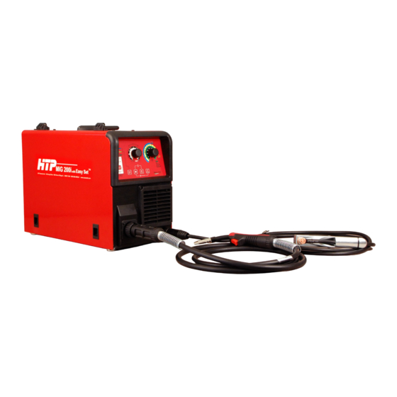
- Page 1 MIG 200i Owner’s Manual 180 Joey Drive Elk Grove Village, IL 60007-1304 Ph: (847) 357-0700 · Fax: (847) 357-0744 Web: www.usaweld.com...
-
Page 2: Manufacturer's Warranty
This warranty shall not apply to any welding machine which has been repaired or altered by unauthorized service departments in any way so as, in the judgment of HTP America, Inc., to affect its stability and reliability, nor which has been subjected to misuse, negligence, or accident. -
Page 3: Electric Shock Can Kill
Electric arc welding produces toxic fumes. Provide adequate ventilation in the welding area at all times. Do not weld on galvanized zinc, cadmium, or lead beryllium materials unless you are POSITIVE that sufficient ventilation is provided. These materials produce toxic fumes. ... - Page 4 Fig. 1...
-
Page 5: General Characteristics
The MIG 200i features an incredible arc dynamic, which makes the MIG 200i suitable for any kind of wire and for any material thickness from 26 gauge up to 1/4”. With the MIG 200i, you can weld in manual mode or in synergic mode with Easy Set™... -
Page 6: Installation
Electrical Connection Your HTP MIG 200i operates on single-phase, 230 volt power (208-240 volt). The machine draws 34 amps out of the wall when operating at a welding output of 200 amps. If you operate the machine on a generator, it needs to be a clean power generator with a minimum of 8500 watts (8500 watts must be the continuous rating or running watts rating of the generator, NOT the peak rating or starting watts rating of the generator). -
Page 7: Front Panel Controls
FRONT PANEL CONTROLS Fig. 2 1) Synergic Mode LED for .035” Welding Wire 2) Synergic Mode LED for .030” Welding Wire/Over-Heat Alarm LED 3) Synergic Mode LED for .023”/.024”/.025” Welding Wire 4) MIG 2T LED 5) MIG 4T LED 6) Select Mode Button 7) Easy Set™... -
Page 8: Front Panel Connections
FRONT PANEL CONNECTIONS Fig. 3 TYPE CONNECTION DESCRIPTION MIG GUN POSITIVE *Factory Setting 7-PIN (The spool gun receptacle does not come preinstalled on your machine. If you choose to purchase the spool gun kit, you SPOOL GUN (Optional) will need to install the 7-pin receptacle and pigtail, which plugs into the PCB.) GROUND NEGATIVE *Factory Setting... - Page 9 MIG WELDING WITH GAS Step by Step Instructions With the Select Mode Button (Fig. 2, #6), select Check the position of the polarity cable. To weld with either MIG 2T or MIG 4T. In MIG 2T, depressing gas, the gun must be set to Positive (+) polarity, and the the trigger makes the wire feed and also ignites an ground cable must be set to Negative (-) polarity.
-
Page 10: Reversing Polarity
SPOOL GUN KIT MIG Welding without Gas Connect the BLACK cable to the + (Ground) The HTP MIG 200i also operates with an optional Connect the cable to the - (MIG Welding Gun) spool gun. You can locate the connection... - Page 11 DUTY CYCLE & OVER-HEAT PROTECTION The HTP MIG 200i is designed for the maintenance welder. It has the ability to weld a lot of different materials and a great variety of thicknesses. Thicker material, depending on type, temperature, etc. may require multi-pass welds.
- Page 12 HTP 15 Series MIG Welding Gun & Parts Part# Description Part# Description A. 15023-10 .023” Contact Tip, 10-Pack 13002-DLT Gas Diffuser A. 15030-10 .030” Contact Tip, 10-Pack 14009 Trigger Switch A. 15035-10 .035” Contact Tip, 10-Pack L. 15100 10’ MIG Gun C.
- Page 13 MIG 200i Wiring Diagram...
- Page 14 MIG 200i Parts Diagram...
- Page 15 MIG 200i Parts List Position Part# Description Position Part# Description 661157 Plastic Frame 644240 Input Power Cable 661062 Knob 660785 Cable Strain Relief 661043 Fan Cover 620751 Tool 600512 Remote Control Receptacle (Optional) 661034 Handle 642740 Ground Receptacle/Socket 619350 Line Filter PCB...
- Page 16 MIG 200i Wire Feed Assembly Parts Diagram MIG 200i Wire Feed Assembly Parts List Position Part# Description 613849 Wire Feed Motor (24V/40W) 634690 Retaining Screw 634990 Euro MIG Gun Adapter 636250 Connecting Screw M12 x 1.5 x 35mm, Brass 636260...
Need help?
Do you have a question about the MIG 200i and is the answer not in the manual?
Questions and answers