Table of Contents
Advertisement
Installation, Operation and
Maintenance Manual
Oil Fired Warm Air Furnace
HO-B Series Up-flow or Horizontal Model
THE INSTALLATION OF THIS FURNACE SHALL BE IN
AUTHORITIES HAVING JURISDICTION AND NFPA
STANDARD 31 (U.S.A.) OR CSA STANDARD B139 (CAN.).
Please read this manual completely
before beginning installation. These
instructions must be kept with the
furnace for future reference.
ACCORDANCE WITH THE REGULATION OF
FOR YOUR SAFETY
Do not store or use gasoline or
other flammable vapors or liquids
in the vicinity of this or any other
appliance.
Oneida Royal Division
Utica, New York
29733 R2 06/01/2003
Advertisement
Table of Contents
Troubleshooting

Summary of Contents for Oneida Royal Air Furnace
- Page 1 Maintenance Manual Oil Fired Warm Air Furnace HO-B Series Up-flow or Horizontal Model THE INSTALLATION OF THIS FURNACE SHALL BE IN ACCORDANCE WITH THE REGULATION OF AUTHORITIES HAVING JURISDICTION AND NFPA STANDARD 31 (U.S.A.) OR CSA STANDARD B139 (CAN.). Please read this manual completely before beginning installation.
- Page 2 Breech Location F – Front In the above example, the furnace is an Oneida Royal Highboy with the 2 exchanger, standard size, front breeched, belt drive, Beckett Oil Burner, 4 tons of cooling. In this Installation, Operation & Maintenance Manual, the models will be abbreviated as 80F for compact models, and 120F for standard models.
-
Page 3: Table Of Contents
Table A-6 Belt Drive Blower Characteristics...20 General Dimensions ...21 Wiring Diagram: Oil Furnace With ST9103 EFT & R7184 Control...22 Wiring Diagram: Oil Furnace With ST9103 EFT & Riello Oil Burner...23 Wiring Notes: ...24 R7184 Detailed Sequence of Operation...25 Table C-1: ST9103 Detailed Sequence of Operation ...29 R7184 LED Diagnostic Light...31... -
Page 4: Introduction
The furnace must be installed and set up by a qualified contractor MODEL 80F Model 80F is an oil-fired upflow forced air furnace, with an output capacity range of 58,100 BTU/Hr. to 78,900 BTU/Hr. The 80F furnace equipped with a direct drive blower may be installed in both horizontal positions. -
Page 5: Horizontal Installation
2 degree slope from the oil burner casing towards the fire pot. Use shims made of noncombustible material. -
Page 6: Non-Suspended Installation
Suggestion; as a measure to prevent fuel oil from accumulating in locations other than the fire pot, as could be the case in the event of nozzle drip, install the furnace with an approximate 2 degree slope from the oil burner casing towards the fire pot. -
Page 7: Chimney Venting
If the chimney serves the furnace only, the vent should be sized at 4 inch minimum, 5 inch maximum. The table below is based on dedicated venting. If the furnace is to be co-vented with other appliances, refer to NFPA 31,... -
Page 8: Barometric Damper Control
The flue pipe should not be smaller in cross sectional area than the flue collar Extend partition on the furnace. The flue pipe should connect to the to floor level. chimney such that the flue pipe extends into, and... -
Page 9: Furnace Controls
CAN/CSA C22.1 Canadian Electrical Code, Part 1, and by local codes, where they prevail. The furnace should be wired to a separate and dedicated circuit in the main electrical panel; however, accessory equipment such as electronic air cleaners and humidifiers may be included on the furnace circuit. -
Page 10: Humidifier
Water or water droplets from the humidifier should not be allowed to come into contact with the furnace heat exchanger. Terminals (115 v) are provided on the ST9103 EFT control. Do not use direct drive motor connections as a source of power for 120 VAC humidifiers and humidifier transformers. -
Page 11: Oil Filter
When using an indoor oil tank, the oil filter may be installed at the tank downstream from the shut-off valve. If firing the furnace under the 0.65 gph rate, a 7 to 10 micron line filter should be installed as close to the oil burner as possible. -
Page 12: Burner Electrodes
Refer to Table A-2, page 18, for Riello oil burner air damper and turbulator settings. DESIGN Figure 5: Note A: Locate hole at least 6 inches on the furnace side of the draft control. Note B: Ideally, hole should be at least 12 inches from breeching or elbow. -
Page 13: Stack Temperature
60° and 90°F for the Model 80F, 55°F and 85°F for the Model 120F. If the venting from the furnace to the chimney is long, or exposed to cold ambient temperatures, it may be necessary to use L-Vent as the vent connector to reduce stack temperature loss to prevent condensation. -
Page 14: Circulating Air Blower
If the joining of the blower speed wiring is done in the YOUR SERVICE furnace junction box, tape off both ends of the unused wire. BELT DRIVE The HO-B Models are available with an optional belt drive blower assembly. -
Page 15: Maintenance And Service
During the routine service, inspect the general condition of the furnace watching for signs of oil leaks in the vicinity of the oil burner, soot forming on any external part of the furnace, soot forming around the joints in the vent pipe, etc. -
Page 16: Furnace Installation Set Up
20. FURNACE INSTALLATION SET UP The furnace must be set up as the final step in the installation. A) The oil burner must be set up following the procedures outlined in section 17: Oil Burner Set Up. -
Page 17: Operating Instructions
Set the manual switch (if installed) in the Electrical Power Supply Line to "OFF". NOTE: If the furnace is to be shut down for an extended period of time, close the oil supply valve to the oil burner. DO NOT ATTEMPT TO START THE BURNER WHEN... -
Page 18: Table A-2 Riello 40F Oil Burner Set-Up
TABLE A-1 BECKETT AFG OIL BURNER SET-UP FURNACE OUTPUT BURNER MODEL BTU/Hr MODEL 1, 2 80F (060) 58,100 AF76BO 80F (070) 68,000 AF76BN 80F (080) 78,900 AF76BN 120F (090) 87,700 AF76BZHS 120F (100) 98,800 AF76BZHS 120F (120) 113,400 AF76BZHS F0 Head required for proper combustion. -
Page 19: Table A-4 Direct Drive Blower Characteristics
FURNACE MOTOR BLOWER MODEL 80F (060) 80F (070) G10 DD ½ 80F (080) 120F (090) G10 DD ½ 120F (100) 120F (120) 120F (090) 120F (100) G12-10 DD ¾ 120F (120) Heating Range values based on temperature rise. Upper values may exceed measured airflow values in Table A-3. -
Page 20: Table A-6 Belt Drive Blower Characteristics
80 (70,000) 80 (80,000) 120 (90,000) 120 (100,000) ½ 120 (120,000) TABLE A-6 BELT DRIVE BLOWER CHARACTERISTICS Furnace Motor Blower Model ½ 120F ½ These formulae will assist with the design of the ductwork and the determination of airflow delivery:... -
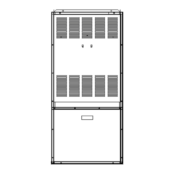
Page 21: General Dimensions
GENERAL DIMENSIONS Cabinet Width Depth Height 49-½ 58-⅛ Table A-6: General Dimensions (inches) Plenum Openings Supply Air Return Air Side Bottom D x E F x G 20½ x 20 14 x 22 14 x 22 120F 20½ x 20 14 x 22 14 x 22 Flue... -
Page 22: Wiring Diagram: Oil Furnace With St9103 Eft & R7184 Control
Appendix B WIRING WIRING DIAGRAM: OIL FURNACE WITH ST9103 EFT & R7184 CONTROL 29733 R2 06/01/2003... -
Page 23: Wiring Diagram: Oil Furnace With St9103 Eft & Riello Oil Burner
Appendix B WIRING WIRING DIAGRAM: OIL FURNACE WITH ST9103 EFT & RIELLO OIL BURNER 29733 R2 06/01/2003... -
Page 24: Wiring Notes
POWER ALTERING NOTE: All thermostat wires for both heating and cooling connect to the furnace at this point. A factory installed wiring harness connects the heating control functions to the R7184 oil primary control. Figure 8, page 14, shows the detail of the timed “Blower Off”... -
Page 25: R7184 Detailed Sequence Of Operation
R7184 DETAILED SEQUENCE OF OPERATION Power is applied to unit. The R7184 completes a self-diagnostic procedure. If no light or flame is present, and unit passes its self-diagnostic procedure, the control enters into the idle mode. Thermostat calls for heat: A. -
Page 26: Sequence Of Operation
IDLE STATE THERMOSTAT CALLS FOR HEAT SAFETY CHECK FOR FLAME (5 SEC.) NO FLAME FLAME BURNER MOTOR & IGNITOR START 15 SEC. SOLENOID VALVE OPENS TRIAL FOR IGNITION BURNER FLAME MONITORED FLAME CARRYOVER STATE · Provides continuous spark · LED diagnostic light ON ·... - Page 27 RIELLO 40F3 TROUBLESHOOTING CHART Thermostat is calling for heat, burner is not running. Burner Starts Test for 120 Vac Supply at sub-base between L and N or terminals #3 and #5. 120 Vac Turn off power supply. Remove control box and jumper terminals #5 and #6. Restore power.
- Page 28 · Low resistance or no contact on starting circuit of coil, terminals #2 and #8. (1.3 ohm ± %). · No oil supply – tank empty, valve closed, dirty filter, damaged supply lines. · Defective or dirty oil valve stem, nozzle, or pump strainer. ·...
-
Page 29: Table C-1: St9103 Detailed Sequence Of Operation
System Response a. ST9103 closes oil primary control T - T connections). b. Ignition system and R7184 oil primary control start the furnace. Oil flows as long as the oil primary control senses flame. c. Burner motor is energized and heat "fan on" delay timing begins. - Page 30 Continued from last page Mode Action Limit switch string opens. (continued) LIMIT Limit switch string closes (with existing call for heat). Limit switch string closes (without existing call for heat). Continuous circulating fan is connected. Electronic Air Cleaner is connected. Humidity control is connected.
-
Page 31: Table C-2: Cad Cell Resistance
R7184 LED DIAGNOSTIC LIGHT The LED diagnostic light has several functions. It indicates the state or mode in which the oil burner is operating. It will also indicate fault conditions, and help determine cad cell resistance while the burner is operating. -
Page 32: Table C-3: R7184 Troubleshooting
HECK RIMARY ONTROL AND If the trouble does not appear to be in the burner or ignition hardware, check the oil primary control and the ignitor by using the following equipment: à screwdriver. à voltmeter (0 - 150 à insulated jumper wires with both ends stripped. TABLE C-3: R7184 TROUBLESHOOTING Condition: Burner motor does not start when there is a call for heat. - Page 33 · Table C-3: R7184 Troubleshooting Procedure 5. Jumper thermostat (T -T) terminals on R7184 IMPORTANT First remove one thermostat lead wire. Condition: Burner starts then locks out on safety with indicator light flashing at 1 Hz rate (½ second on, ½ second off) Procedure 1.
- Page 34 Table C-3: R7184 Troubleshooting Procedure 5. Jumper thermostat (T -T) terminals on R7184 IMPORTANT First remove one thermostat lead wire. Condition: Burner starts then locks out on safety with indicator light flashing at 1 hz rate (½ second on, ½ second off) 6.
- Page 35 Table C-3: R7184 Troubleshooting Procedure 9. Check cad cell sighting for view of flame. · Disconnect line voltage power and open line switch. · Unplug cad cell and clean cad cell face with soft cloth. Check sighting for clear view of flame.
-
Page 36: Table C-4: System And General Troubleshooting
Check furnace switch, main electrical panel furnace fuse or circuit breaker. Also look for any other hand operated switch, such as an old poorly located furnace switch which was not removed during furnace replacement. Remove thermostat wires from oil primary control terminals T-T. - Page 37 & G ABLE YSTEM ENERAL Problem Possible Cause No fuel oil. Clogged nozzle. Furnace will not start Clogged oil filter. without first pushing oil primary control reset button. Low oil pump pressure. (Happens on frequent basis) Air getting into fuel oil...
- Page 38 C-4: S & G ABLE YSTEM ENERAL Problem Possible Cause Electrodes out of adjustment or defective. Poor transformer high voltage connections or defective transformer. Oil burner sputtering at nozzle Fuel oil filter clogged. Defective oil pump. Fuel oil line partially clogged or contains air.
- Page 39 Check blower fan motor amperage draw. Check motor ventilation ports, clean if necessary. Replace motor if necessary. Check burner motor. Replace if necessary. This is not likely to be a furnace problem. Balance duct system. Clean or replace air filter. Check all dampers. Open closed dampers including registers in unused rooms.
-
Page 40: Home Owner's Reference Table
HOME OWNER’S REFERENCE TABLE: Installation Contractor: Model No. Serial No. Date Installed Contractor Contact Address Postal Code Telephone No. After Hours No. Service Contractor if different from Installation Contractor: Service Tech. Telephone No. After Hours No. Fuel Supplier: Oil Supplier Contact Telephone No.
Need help?
Do you have a question about the Air Furnace and is the answer not in the manual?
Questions and answers