
Related Manuals for GE PDS22xxP series


Summary of Contents for GE PDS22xxP series
- Page 1 GE Consumer & Industrial TECHNICAL SERVICE GUIDE 2003 Electronic Bottom-Mount Refrigerators MODEL SERIES: GBS22_ _P GBS20_ _P PDS22_ _P PDS20_ _P PUB # 31-9112 1/04...
- Page 2 If grounding wires, screws, straps, clips, nuts, or washers used to complete a path to ground are removed for service, they must be returned to their original position and properly fastened. GE Consumer & Industrial Technical Service Guide Copyright © 2004 All rights reserved.
-
Page 3: Table Of Contents
Table of Contents Airflow ........................6 (Cabinet Interior) Air Flow Tower and Damper ......................11 Component Locator Views ......................9 Components ..........................10 Control Diagnostics ........................18 Control Features ........................... 8 Diagnostics Chart ........................19 Doors ............................4 Door Gaskets ..........................17 Door Handles .......................... -
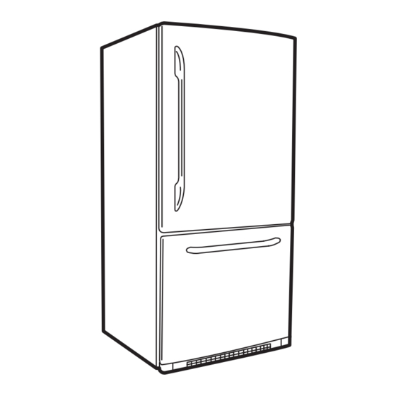
Page 4: Doors
Installation Freezer Door Doors 1. Install 2 door mounting screws on the freezer The swing direction of the fresh food door and the compartment door. freezer door can be reversed on all models except stainless steel. 2. Insert the door handle onto the door mount screws and pull the handle firmly to the left. - Page 5 Troubleshooting Tips - Handle Installation Problem Possible Causes What To Do Handle too hard to Mounting bolts too tight. Remove the handle. Loosen the mounting bolts slightly so that the handle will snap into place install/Handle requires when installed. excessive force to install Defective mounting bracket or Remove handle.
-
Page 6: Technical Data
Technical Data ELECTRICAL SPECIFICATIONS Airflow (Cabinet Interior) Temperature Control (Position 5)....... 32 - 4°F The evaporator fan forces air through the Defrost Control... 60 hrs @ 40 mins with no door opening evaporator into the freezer compartment. Overtemperature Thermostat....... 140 - 110°F Air from the evaporator is also forced through the Defrost Thermistor..........70°F electronic damper to the top of the air tunnel,... -
Page 7: Nomenclature
S = STANDARD G = GE H = UPGRADE GLASS P = 2003 SS = STAINLESS/STAINLESS K = SPILL-PROOF GLASS P = PROFILE (GE) CC = BISQUE/BISQUE M = SPILL-PROOF/SLIDE-OUT GLASS BB = BLACK/BLACK S = STAINLESS STEEL DOORS Serial Number... -
Page 8: Control Features
Control Features Electronic Control Panel Knob Control Panel (Encoder) – 8 –... -
Page 9: Component Locator Views
Component Locator Views Fresh Food Section Control Panel Thermistor Lights and Filter Thermostat Air Flow Tower Damper (Inside Tower) Freezer Section Light and Thermostat Icemaker (When Installed) Evaporator Thermistor Evaporator Thermostat Evaporator Thermistor (Behind Panel) (Behind Panel) (Behind Panel) Machine Compartment Compressor Condenser Water Valve... -
Page 10: Components
Components 4. Unplug the fresh food light connector from the Knob (Encoder) compartment ceiling. Electronic and mechanical control panels are removed in the same manner. Removal and Replacement 1. Remove the fresh food light cover. 2. Remove the 2 screws that hold the rear of the control housing to the liner ceiling. -
Page 11: Air Flow Tower And Damper
Air Flow Tower and Damper Water Filter The air flow tower contains an internal damper. On ice maker models, the water filter is located in The damper and tower are replaced as one unit. the upper, right corner of the fresh food compartment. -
Page 12: Fresh Food And Freezer Thermistors
The fresh food thermistor is located on the ceiling Icemaker Ready Models of the fresh food compartment behind the light assembly. The accessory icemaker can be purchased through parts, part # IM6 or as a sales accessory, part # IM4A through a dealer. The icemaker must be installed with the fill tube shipped with the refrigerator. -
Page 13: Evaporator Fan
Note: Some of the foam insulation may need to be Evaporator Thermistor removed to expose the thermistor and wire. The evaporator thermistor is located on top of the evaporator behind the rear panel of the freezer compartment. The thermistor is held in place by a tie strap. -
Page 14: Evaporator Thermostat
Note: The resistance of the thermostat and defrost Evaporator Thermostat heater can be taken by removing the access panel The defrost heater is controlled by the evaporator located in the upper left section of the evaporator thermistor and normally turns off at 70°F. If the cover. -
Page 15: Fresh Food And Freezer Light Thermostats
Note: To gain better access to the thermostat, pull Fresh Food and Freezer Light the housing down until there is enough room to Thermostats remove the thermostat. Fresh Food Light Thermostat The fresh food light thermostat interrupts power to the fresh food lights when the temperature reaches 175°F. -
Page 16: Freezer Drawer And Slides
5. Set the drawer on a non-scratching surface. Freezer Drawer and Slides 6. Remove the middle basket, top basket, ice tray Removal and Replacement shelf, and ice bin. 1. Open the freezer drawer until it stops. 7. The center rail assembly is held in place by a molded channel in the freezer ceiling and 2. -
Page 17: Door Gaskets
10. Pull the front edge of the plastic support Freezer Drawer Shim housing away from the side wall. Pull the If the drawer is not sealing correctly and the gasket housing forward to disengage the rear tabs. is not damaged, the door alignment can be Note: The plastic housing may be tight against adjusted. -
Page 18: Control Diagnostics
Troubleshooting 1. Enter the diagnostic mode by pressing both Control Diagnostics the freezer temperature ( COLDER WARMER pads and the refrigerator temperature ( A diagnostic aid can be assembled which consists COLDER ) pads simultaneously. of a control board, membrane and wiring harness. WARMER The parts required are WR55X10120, Note: All four pads must be held for approximately... -
Page 19: Diagnostics Chart
Diagnostics Chart Condenser Fan Noise Photo Shown with Plenum in the Bent Position Symptom: Loud airflow noise coming from the Screw Tab condenser fan compartment. Problem: The plenum is bent out of position due to the screw tab being tightened at an angle. Solution: Release the tension off the plenum by loosening the screw tab. -
Page 20: Strip Circuits
Strip Circuits 3-Wire Electronic Temperature Control 6-Wire Encoder Temperature Control Damper Thermistors Condenser and Evaporator Fan – 20 –... - Page 21 Freezer Light Fresh Food Light Compressor Defrost Heater – 21 –...
-
Page 22: Schematics
Schematics Drawer Models LEGEND BK: BLACK BN: BROWN RD: RED BO: BRIGHT ORANGE BL: BLUE GY: GREY GN: GREEN YL: YELLOW WH: WHITE PR: PURPLE SB: SKY BLUE PK: PINK – 22 –... -
Page 23: Bk: Black Bn: Brown Rd: Red
Door Models LEGEND BK: BLACK BN: BROWN RD: RED BO: BRIGHT ORANGE BL: BLUE GY: GREY GN: GREEN YL: YELLOW WH: WHITE PR: PURPLE SB: SKY BLUE PK: PINK – 23 –... -
Page 24: Illustrated Parts Catalog
Illustrated Parts Catalog Note: Exploded views and parts list are for illustration only. Refer to parts catalog for specific model information. PDS22AMBPAWW Shown – 24 –... - Page 25 – 25 –...
- Page 26 – 26 –...
- Page 27 PDS22AMBPAWW Shown VIEW CATALOG DESCRIPTION QUANTITY NUMBER NUMBER 31-46043 HANDLE INSTRUCTIONS 31-46169 INSTALL INSTRUCTION 31-51515 MINI MANUAL 49-60282 USE AND CARE WR78X10943 DOOR FOAM ASS'Y,FZ WR14X10184 GASKET ASSEMBLY,F WR14X10185 GASKET ASSEMBLY,R WR17X11585 GUIDE,RAIL(ICE)BIN WR78X10944 DOOR FOAM ASS'Y,R WR04X10138 NAME PLATE WR02X11722 CAP,HINGE(C) WR02X11721...
- Page 28 PDS22AMBPAWW Shown VIEW CATALOG DESCRIPTION QUANTITY NUMBER NUMBER WR02X11687 CONNECTOR,DOOR WR02X11689 SHUTTER SLIDE WR72X10148 SLIDE ASS'Y LEFT WR02X11679 BRACKET,HANDLE FF WR02X11678 BRACKET,HANDLE FZR(L) WR02X11672 LEVER,SHUTTER WR85X10057 EVAPORATOR ASS'Y WR55X10025 SENSOR TEMP FF WR02X11677 BRACKET,HANDLE FZR WR02X11703 SUPPORTOR COVER T/V WR02X11698 ROLLER WR02X11671 ADJUSTER...
- Page 29 PDS22AMBPAWW Shown VIEW CATALOG DESCRIPTION QUANTITY NUMBER NUMBER WR02X11699 SOCKET ASSEMBLY,LAMP(F) WR02X11700 SOCKET ASSEMBLY,LAMP(R) WR50X10050 THERMODISC FF WR23X10341 SWITCH LIGHT FZ WR23X10342 SWITCH LIGHT FF WR02X11661 COVER LAMP FF WR02X11658 COVER LAMP FZ WR30X10048 TRAY DRIP WR60X10146 EVAP MOTOR ASS'Y WR02X11702 HOLDER,DRIER WR17X11594...
-
Page 30: Warranty
Warranty Information – 30 –...