
Summary of Contents for INTARCON MCV-N
- Page 1 User & Installation Manual intarblock intartop MCV-N, MCV-C MCR-N, MCR-C BCV-N, BCV-C BCR-N, BCR-C MCV-I, BCV-I Doc. CV / CR 3.3 January 2018...
- Page 2 I. Quick Start Guide Congratulations! You have acquired a high quality cooling unit. Your INTARBLOCK and INTARTOP units are specially designed to equip positive temperatura cold romos in the range from -5ºC (23ºF) to +10 ºC (50ºF), and from -15ºC (5ºF) to -25ºC (13ºF), depending on the range. Once installed, your INTARSPLIT unit can be fully operated from the remote keyboard.
-
Page 3: Table Of Contents
intarblock | intartop Basic keyboard functions.- To switch ON and OFF the instrument. To switch ON and OFF the room light. To visualise maximum room temperature record In programming mode it increases the displayed value or explores the parameter list. by pressing the key for 3 seconds the fast cooling cycle starts. -
Page 4: Description
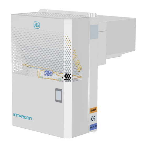
1. DESCRIPTION INTARBLOCK and INTARTOP units are monoblock refrigeration units in vertical and roof construction, fullly tested and adjusted in Factory. They are assembled on a prelacquered galvanised steel shell and have been designed for indoor installation, with easily removable panels to give access to fans, refrigerant circuit, and electric board. -
Page 5: Operation
intarblock | intartop 3. OPERATION INTARBLOCK and INTARTOP are refrigeration machines operating under a vapour compression cycle. Refrigeration cycle The refrigeration cycle uses a phase change refrigerant fluid in a closed circuit, with the following four steps: Expansion: refrigerant expansion takes place in the capillary tube between high and low pressure sections. -
Page 6: Operation Limits
CAPILLARY TUBE / THERMOSTATIC CONDENSER EVAPORATOR EXPANSION VALVE FILTER DRAIN TRAY SOLENOID VALVE COMPRESSOR DRAIN BUCKET PRESSURE REGULATOR (only BCV/BCR) 4. OPERATION LIMITS INTARBLOCK and INTARTOP units are designed for continuous operation within the following temperature limits: Cold Room Temperature Ambient Temperature +10 ºC (50ºF) -5 ºC (23ºF) -
Page 7: Composition
intarblock | intartop 5. COMPOSITION MCV / BCV units are built on a self-contained construction. The components are assembled on a steel structure and covered with a prelacquered galvanised steel shell. It consists of: Refrigerant circuit § Hermetic reciprocating compressor with internal protection, assembled on silentblocs §... -
Page 8: Tests
- V820 keyboard. § Compressor permanent condenser in single phase units. § Compressor start relay and condenser in single phase units. § Ground connection for compressor and motorfans. § Cold room light. § Door microswitch connection. § Door microswitch (as an option). §... -
Page 9: Mcv Series Technical Features
intarblock | intartop 8. MCV SERIES TECHNICAL FEATURES MCV Series R404A 0008 0010 0012 1010 1012 1014 1016 1018 1024 2024 2026 2034 3034 3038 Cooling capacity (1) (W) 930 1077 1184 1347 1468 1917 2149 2391 2690 3020 Cooling Absorbed power (2) (W) 869 1020 1175 1356 1474 1946 2070 1970... - Page 10 MCV series R134a 0010 0015 1015 1026 1033 2033 2053 3053 3074 3108 Cooling capacity (1) (W) 972 1281 1454 1790 2153 2489 3239 3927 Cooling capacity Absorbed power (2) (W) 570 810 920 1090 1460 1510 1890 2480 COP performance 1,42 1,50 1,71 1,58 1,58 1,64 1,47 1,65 1,71 1,58...
-
Page 11: Bcv Series Technical Features
intarblock | intartop BCV SERIES TECHNICAL FEATURES BCV Series R404A 0018 1018 1026 1034 2034 2054 2074 3074 3086 3096 Cooling capacity (1) (W) 1048 1349 1633 1930 2270 2460 Cooling capacity Absorbed power (2) (W) 1136 1187 1685 2014 2380 2320 2640... -
Page 12: Mcr Series Technical Features
10. MCR SERIES TECHNICAL FEATURES 0008 0010 0012 MCR Series R404A 1010 1012 1014 1016 1018 1024 2024 2026 2034 Cooling capacity (1) (W) 1087 1194 1378 1478 2020 2223 2527 Cooling Absorbed power (2) (W) 1038 1201 1319 1425 1903 capacity COP performance... - Page 13 intarblock | intartop MRC series R134a 0010 0015 1015 1026 1033 2033 2053 2074 Cooling capacity (1) (W) 1265 1502 1911 2352 2940 Cooling capacity Absorbed power (2) (W) 1050 1210 1670 1830 COP performance 1,41 1,48 1,72 1,36 1,43 1,58 1,41 1,61...
-
Page 14: Bcr Series Technical Features
11. BCR SERIES TECHNICAL FEATURES BCR Series R404A 0008 1018 1026 1034 2034 2054 2074 Cooling capacity (1) (W) 1102 1443 1689 Cooling capacity Absorbed power (2) (W) 1160 1297 1830 2147 COP performance 0,81 0,75 0,79 0,76 0,85 0,79 0,79 Installed power (3) (kW) 0,87... -
Page 15: Cooling Capacity R404A
intarblock | intartop 12. COOLING CAPACITY R-404A § MCV series Cold room temperature Capacity (W) -5 ºC 0 ºC +5 ºC +10 ºC Cooling Cooling Cooling Cooling Absorbed Absorbed Absorbed Absorbed capacity capacity capacity capacity MCV series power (W) power (W) power (W) power (W) 0008... - Page 16 § MCR Series Cold room temperature Capacity (W) -5 ºC 0 ºC +5 ºC +10 ºC Cooling Cooling Cooling Cooling Absorbed Absorbed Absorbed Absorbed capacity capacity capacity capacity MCR Series power (W) power (W) power (W) power (W) 0008 0010 1055 0012 1012...
- Page 17 intarblock | intartop 13. COOLING CAPACITY R-134a · Serie MCV Cold room temperature Capacity (W) 0 ºC +5 ºC +10 ºC Cooling Absorbed Cooling Absorbed Cooling Absorbed MCV Series capacity (W) power (W) capacity (W) power (W) capacity (W) power (W) 0010 0015 1139...
-
Page 18: Dimensions
14. DIMENSIONS CV-N-C Models Centrifugal Box only in 0 series PLUG-IN FRAME DROP FRAME Exhaust Dimensions (mm) duct 0 series Ø 150 1 series Ø 150 2 series Ø 150 3 series 2x Ø 150 CV-I Models Dimensions (mm) 1 series 1060 2 series 1100... - Page 19 intarblock | intartop CR-N Models ROOF FRAME CR-C Models Dimensions (mm) Exhaust duct 0 series Ø 150 1 series Ø 150 2 series Ø 150...
-
Page 20: Electrical Connections
15. ELECTRICAL CONNECTIONS Before connecting the unit to the electrical supply, make sure that the electrical board is in good conditions and please follow the following recommendations: § Consult the electrical schema supplied by manufacturer. § Only use electrical cables of the appropriate characteristics and capacity according to the following table. -
Page 21: Emergency System
intarblock | intartop 16. EMERGENCY SYSTEM The electronic regulation of the units involves control routines and emergency alarms for the following causes: § Probe failure. § Too high and too low room temperature. § Too high or too low refrigerant pressure. §... -
Page 22: Data Plate
19. DATA PLATE All All units are identified with the following data plate. In all communications with the manufacturer please indicate the serial number. 20. SAFETY RECOMMENDATIONS The start-up of the unit and its reparation must be carried out by qualified personnel. To minimise the risk of accidents during the installation, start up or maintenance tasks, below instructions must be followed. -
Page 23: Installation And Mounting
intarblock | intartop In case of accident due to refrigerant inhalation follow the following instructions: § Move the victim where it could breathe fresh air. The victim should lay on its back or its shoulder. § Call emergency services if needed. In case of eye injures due to refrigerant splatters: §... - Page 24 DOOR HEATER (Only BCV) DOOR MICROSWITCH COLD ROOM LIGHT SIDE COVER DRAIN PIPE RECOMMENDED SEPARATION 1 000 mm § Plug in mounting.- on an existing cold room or new one: 1. Cut out the indicated frame on the wall panel. 2.
- Page 25 intarblock | intartop Dimensions (mm) +0 +5 ±1 ±1 CV series 0 (plug-in mounting) Ø6 Ø6 Ø6 Ø6 Ø6 Ø6 Ø8 Ø8 Ø2 Ø6 Ø6 Ø6 Ø6 Ø6 Ø6 DROP MOUNTING PLUG-IN MOUNTING Dimensions (mm) +0 +5 ±1 ±1 ±1 ±1 ±2 CV series 1...
- Page 26 § Centrifugal fan installation.- for CV-CF models. 1. Fix the unit to the cold room wall before installing the centrifugal fan. 2. Take out the side panels of the centrifugal box to access the fixing screws. 3. Screw the centrifugal box to the refrigeration unit and connect the fan electrical wiring. 4.
-
Page 27: Start-Up
intarblock | intartop Air flow A.s.p. Recommended duct dimensions (mm) CV/CR -C m³/h Semi-flexible Rigid (PVC or steel) CV 0 series Ø 200 Ø 150 < 20 m: Ø 150 CV 1 series Ø 250 >20 m: Ø 200 CV 2 series Ø... -
Page 28: Maintenance
Finally you can easily test the proper operation of some of the safety devices such as: § Open door alarm.- by leaving the door open beyond indicated in doA parameter. § High pressure switch or high temperature alarm.- by intentionally obstructing the air intake of condenser. -
Page 29: Refrigerant Load
intarblock | intartop § Cleaning the evaporator (CR).- Remove the evaporator cover panel from inside cold room. Deplace the cover to a side to access the coil. Blow or brush to clean it. CONDENSATION COIL GRILLE EVAPORATOR COVER PANEL § Drain tray.- To clean the drain tray you can use commercial detergents. In that case, make sure to remove the detergent from the drain bucket inside the condensation block. -
Page 30: Disposal Management
25. DISPOSAL MANAGEMENT After the installation dispose the packaging and pallet in an environmentally friendly manner and according to your regulations. When disposing your unit or any of its parts, do it through an authorised waste management company according to laws and regulations. 26. - Page 31 intarblock | intartop Fan LED Defrosting LED Compressor LED Fast-cooling mode LED Digital display Alarm LED Defrosting key Max. Temperature and fast- cooling mode key Cold room Light switch Min temperature key Energy saving mode key Target temperatura and validation key Unit On/Off To display and modify target set point;...
- Page 32 Keyboard functions § To switch off the unit.- 1. hold pressed for 5 seconds and the display will show "OFF". § To show maximum temperature record.- 1. press 2. the display will show the value together with “Hi”. 3. press or wait 5 seconds to restore the normal display.
-
Page 33: Parameter List
intarblock | intartop 3. press to modify its value. 4. press set to confirm then ew value and jump to the next parameter. 5. to exit the programming mode press set and or wait for 15 seconds. § To lock the keyboard.- 1. - Page 34 Code Description Range Default List Interval between defrosting cycles. 1 ÷ 120 h Maximum defrosting legth. 0 ÷ 255 min 15 min dFd Display during defrost: rt, it,Set, dEF, rt=real temperature ; it=last recorded temperature ; Set=set point ; dEF= “dEF” message ; dEG= “dEG”message. Delay after defrosting to display cold room temperature 0 ÷...
- Page 35 intarblock | intartop Code Description Range Default List nPS Pressure switch activation number 0 ÷ 15 ANALOGUE INPUTS -12,0 ÷ 12,0 Thermostat probe calibration ºC Evaporator probe -12,0 ÷ 12,0 ºC Condenser probe calibration -12,0 ÷ 12,0 ºC P2P Evaporator probe presence: n - y n=no (defrosting by time) ;...
- Page 36 External communication By mean of the TTL connector it is possible to connect the unit through a ModBUS-RTU compatible net to a XWEB300 monitoring system. Same TTL input is used to download or upload parameter data from a “Hot key”. Alarm signals Message Cause Output...
-
Page 37: Fault Analysis
intarblock | intartop 28. FAULT ANALYSIS Syptom Cause Solution The unit does not turn on a) faulty power supply a) Check protections, fuse, etc. b) wrong connection of remote keyboard b) Check connection and polarity The compressor does a) faulty power supply a) Check protections, fuse, etc. - Page 38 Syptom Cause Solution The unit runs but the a) Faulty room temperature probe a) Check the probe value and calibrate room temperature does b) Too often defrost cycles through parameters, check probe connections, not goes down c) Too small unit for the room size or replace probe.
- Page 39 intarblock | intartop Syptom Cause Solution The condenser fan a) Condensation control is not working a) Compare Pb3 value by checking with a works inttermitently and properly (only for split units) reliable thermometer, check probe isolation, subsequently the replace probe and isolate it properly. Check pressure switch turns off HP and LP values performance during starting the unit.
-
Page 40: Guarantee
29. GUARANTEE Validation of guarantee.- The user is called to fill the form trough INTARCON’s web site: http://www.intarcon.com/en/contacto/registro-garantia/ during the following 20 days after the purchasing date. Otherwise, the guarantee period will be in effect from the manufacturing date. Coverage.- The manufacturer guarantees the products against any manufacturing default or working vice for 12 months after the validation of the guarantee or from the manufacturing date. - Page 44 Headquarters and factory Pol. Ind. Los Santos, Bulevar de Los Santos, 34, Po box. 410 14900 - Lucena - Córdoba (SPAIN) Tlf. +34 957 50 92 93 www.intarcon.com...
Need help?
Do you have a question about the MCV-N and is the answer not in the manual?
Questions and answers