Advertisement
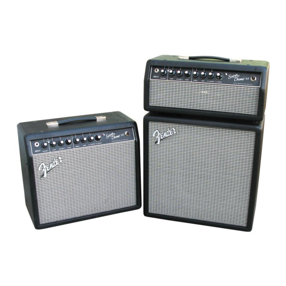
SUPER CHAMP X2 COMBO/ HEAD™
(This is the model name for warranty claims)
COMBO p/n 2223000000 (120V)
HEAD p/n 2223100000 (120V)
SERVICE MANUAL
ATTENTION:
WARRANTY SERVICE PROCEDURES
The Super Champ X2 Combo and Head are considered to be field serviceable to the
component level. Except for the µDSP PCB which must be replaced as a complete
module. We do however understand that some circumstances may require replacement of
other PCB Assemblies. Any Fender Authorized Service Center in need of a warranty
replacement PCB Assembly for this unit should contact FMIC Tech Support by phone at
(866) 345-3642 or email: sevice@fender.com
Fender Musical Instruments Corporation, 17600 North Perimeter Drive, Suite 100 Scottsdale, AZ 85255
Issued: March 2012
Advertisement
Table of Contents

Related Manuals for Fender SUPER CHAMP X2 COMBO


Summary of Contents for Fender SUPER CHAMP X2 COMBO
-
Page 1: Service Manual
ATTENTION: WARRANTY SERVICE PROCEDURES The Super Champ X2 Combo and Head are considered to be field serviceable to the component level. Except for the µDSP PCB which must be replaced as a complete module. We do however understand that some circumstances may require replacement of other PCB Assemblies. -
Page 2: Parts List Codes
Musical Instruments Corporation. It is not to Corporation. be sold or assigned to another party and is dis- closed solely for use by Fender Authorized Parts marked with two asterisks ( Service Centers for purposes of product service ) indicate the and maintenance. -
Page 3: Specifications
SUPER CHAMP X2 COMBO/HEAD™ (This is the model name for warranty claims) SPECIFICATIONS Model Name: SUPER CHAMP X2 COMBO/ HEAD Release Number: PR 2259 PR 2260 HEAD COMBO Part Numbers (120V, 60Hz) US: 2223000000 2223100000 (230V, 50Hz) EUR: 2223006900 2223106900... -
Page 4: Service Notes
Op-amp U6-A provides the high impedance instru- shooting. Information is focused for its effective use ment input with 14db of gain. Op-amp U6-B is while maintaining the security of Fender® proprie- configured as an active filter producing high fre- tary information whenever possible. -
Page 5: User Interface
SUPER CHAMP X2 COMBO/HEAD™ (This is the model name for warranty claims) ROUT signals are the input to the differential amp which acts as a three pole active low pass filter for µDSP PCB de-emphasis. The output of U3-A is applied to a buffer amp U1-A which drives op-amp U1-B which The µDSP PCB is located in the back of the chassis... -
Page 6: Parts List
+ * Access to this part or assembly is controlled. Please contact the FMIC Customer Service Department. ** Safety Requirement part. Replacement must match Safety Agency…–Value, if specified –Type, if specified –Approval Mark(s) if on part. shaded + ** Both a unique Fender® part and a Safety Requirement part as defined above. - Page 7 + * Access to this part or assembly is controlled. Please contact the FMIC Customer Service Department. ** Safety Requirement part. Replacement must match Safety Agency…–Value, if specified –Type, if specified –Approval Mark(s) if on part. shaded + ** Both a unique Fender® part and a Safety Requirement part as defined above.
-
Page 8: Chassis Assembly
+ * Access to this part or assembly is controlled. Please contact the FMIC Customer Service Department. ** Safety Requirement part. Replacement must match Safety Agency…–Value, if specified –Type, if specified –Approval Mark(s) if on part. shaded + ** Both a unique Fender® part and a Safety Requirement part as defined above. - Page 9 + * Access to this part or assembly is controlled. Please contact the FMIC Customer Service Department. ** Safety Requirement part. Replacement must match Safety Agency…–Value, if specified –Type, if specified –Approval Mark(s) if on part. shaded + ** Both a unique Fender® part and a Safety Requirement part as defined above.
- Page 10 + * Access to this part or assembly is controlled. Please contact the FMIC Customer Service Department. ** Safety Requirement part. Replacement must match Safety Agency…–Value, if specified –Type, if specified –Approval Mark(s) if on part. shaded + ** Both a unique Fender® part and a Safety Requirement part as defined above.
- Page 11 + * Access to this part or assembly is controlled. Please contact the FMIC Customer Service Department. ** Safety Requirement part. Replacement must match Safety Agency…–Value, if specified –Type, if specified –Approval Mark(s) if on part. shaded + ** Both a unique Fender® part and a Safety Requirement part as defined above.
- Page 12 + * Access to this part or assembly is controlled. Please contact the FMIC Customer Service Department. ** Safety Requirement part. Replacement must match Safety Agency…–Value, if specified –Type, if specified –Approval Mark(s) if on part. shaded + ** Both a unique Fender® part and a Safety Requirement part as defined above.
- Page 13 SUPER CHAMP X2 COMBO/HEAD™ (This is the model name for warranty claims) Service Diagram List Service Diagram COMBINED .... SUPER CHAMP X2 MAIN PCB Service Diagram COMBINED .... SUPER CHAMP X2 USB PCB Footswitch Assembly .... 2-BUTTON FOOTSWITCH Service Diagram (PCB Assembly) …..2-BUTTON FOOTSWITCH...
- Page 14 Z2259S1_A.sch-1 - Fri Jun 15 09:54:06 2012...
- Page 15 Z2259S1_A.sch-2 - Fri Jun 15 09:54:06 2012...
Need help?
Do you have a question about the SUPER CHAMP X2 COMBO and is the answer not in the manual?
Questions and answers