Table of Contents
Advertisement
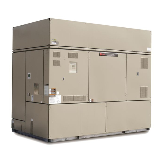
Installation, Operation,
and Maintenance
IntelliPak™ ™ Commercial Self-Contained
Signature Series
20 to 110 Tons
S S C C W W F F a a n n d d S S I I W W F F – 20 to 110 Ton
S S C C R R F F a a n n d d S S I I R R F F – 25 to 60 Ton
Only qualified personnel should install and service the equipment. The installation, starting up, and servicing of heating, ventilating, and
air-conditioning equipment can be hazardous and requires specific knowledge and training. Improperly installed, adjusted or altered
equipment by an unqualified person could result in death or serious injury. When working on the equipment, observe all precautions in the
literature and on the tags, stickers, and labels that are attached to the equipment.
June 2018
S S A A F F E E T T Y Y W W A A R R N N I I N N G G
S S C C X X F F - - S S V V X X 0 0 1 1 Q Q - - E E N N
Advertisement
Table of Contents

Related Manuals for Trane IntelliPak SCWF 20


Summary of Contents for Trane IntelliPak SCWF 20
- Page 1 Installation, Operation, and Maintenance IntelliPak™ ™ Commercial Self-Contained Signature Series 20 to 110 Tons S S C C W W F F a a n n d d S S I I W W F F – 20 to 110 Ton S S C C R R F F a a n n d d S S I I R R F F –...
-
Page 2: Important Environmental Concerns
A A L L W W A A Y Y S S r r e e f f e e r r t t o o a a p p p p r r o o p p r r i i a a t t e e M M a a t t e e r r i i a a l l S S a a f f e e t t y y impact to the environment. Trane advocates the... - Page 3 This document and the information in it are the property of Trane, and may not be used or reproduced F F a a i i l l u u r r e e t t o o f f o o l l l l o o w w i i n n s s t t r r u u c c t t i i o o n n s s b b e e l l o o w w c c o o u u l l d d r r e e s s u u l l t t i i n n in whole or in part without written permission.
-
Page 4: Table Of Contents
Table of Contents Overview ........8 Duct Connections. - Page 5 T T a a b b l l e e o o f f C C o o n n t t e e n n t t s s Wiring ......49 Tracer Summit System .
- Page 6 Intermediate Piping ....64 Trane Communications Unit Airside Components....65 Modules .
- Page 7 T T a a b b l l e e o o f f C C o o n n t t e e n n t t s s Units with Hydronic Heat ....80 Refrigerant System .
-
Page 8: Overview
Refer to previous IOM versions for R-407C and R-22 and low pressure cutout switches, discharge line check units, or contact your local Trane representative. valve and liquid line solenoid valve. Refer to the appropriate IOM for air-cooled condenser All units include liquid line service valves for each CXRC-SVX01*-EN and programming IntelliPak™... -
Page 9: Standard Controls
Internally trapped drain for low cost installation Waterside valve package option to enhance system Trane 3-D® Scroll Compressor efficiency for reliability, efficiency and quiet operation Two-bolt connection on cleanable condenser for quick, easy maintenance Standard Controls... -
Page 10: Optional Controls
O O v v e e r r v v i i e e w w Optional Controls Figure 2. Right side view of unit Optional controls include a disconnect switch, dirty filter switch, water flow switch (water-cooled only), supply air temperature reset, or external setpoint inputs. -
Page 11: Model Number Description
Model Number Description Commercial Self-Contained Signature Series Digit 1 — Unit Model Digit 10, 11 — Design Sequence Digit 17, 18, 19 – Fan RPM S = Self-Contained ** = Factory Assigned 040 = 400 rpm 045 = 450 rpm 050 = 500 rpm Digit 2 —... - Page 12 M M o o d d e e l l N N u u m m b b e e r r D D e e s s c c r r i i p p t t i i o o n n Digit 25—...
-
Page 13: Commercial Self-Contained Air-Cooled
M M o o d d e e l l N N u u m m b b e e r r D D e e s s c c r r i i p p t t i i o o n n Commercial Self-Contained Air-Cooled Condenser Digit 1 —... -
Page 14: General Data
General Data Table 1. SCWF/SIWF Water-cooled self-contained, 20 to 42 tons Unit Size Compressor Data Quantity Nominal Ton/comp 15/10 15/10 10/15 Evaporator Coil Data Circuits Rows 3 or 6 4 or 6 4 or 6 Sq. Ft. 21.81 21.81 21.81 29.98 29.98 31.35... - Page 15 100/53/0 26/0 Notes: Compressors are Trane 3-D™ scroll. All units operate with R-410A. Units ships with full operating charge. Maximum cfm limits are set to prevent moisture carryover on the evaporator coil. Minimum cfm limits are set to ensure stable thermal expansion valve operation at low load conditions.
- Page 16 38/19/0 33/17/0 Notes: Compressors are Trane 3-D™ scroll. All units operate with R-410A. Units ships with full operating charge. Maximum cfm limits are set to prevent moisture carryover on the evaporator coil. Minimum cfm limits are set to ensure stable thermal expansion valve operation at low load conditions.
- Page 17 At conditions of 95° F (35° C), condenser storage capacity is 95% full. To determine the correct amount of refrigerant needed for a particular application, reference the Trane Reciprocating Refrigeration Manual. Table 5. SCWF/SIWF water volumes Water Volume in U.S. Gallons / Liters...
- Page 18 G G e e n n e e r r a a l l D D a a t t a a Table 6. SCWF/SIWF Refrigerant circuits, number of compressors by circuit Circuit Unit Size 20/22/25 Ton 1- 10T 1- 10T 29/32 Ton 1- 15T 1- 10T...
- Page 19 Notes: Hot water and steam heating coils have Prima-Flo® fins without turbulators. For coil capacities, use TOPSS™ (Trane Official Product Selection Program). Full capacity coils consist of two coils stacked and piped in parallel. Table 11. Waterside economizer coil physical data...
- Page 20 G G e e n n e e r r a a l l D D a a t t a a Table 11. Waterside economizer coil physical data (continued) Height Length Type (in) (in) Model Unit Size Rows SCXF 42 &...
-
Page 21: Pre-Installation
N N o o t t e e : : Notify your Trane representative of the damage Unit Inspection and arrange for repair. Have the carrier inspect... -
Page 22: Unpacking
P P r r e e - - I I n n s s t t a a l l l l a a t t i i o o n n Inspection for Concealed Damage • The owner must provide reasonable evidence that the damage did not occur after delivery. -
Page 23: Unit Protective Covers
P P r r e e - - I I n n s s t t a a l l l l a a t t i i o o n n Unit Protective Covers N N o o t t e e s s : : •... -
Page 24: Dimensional Data
Dimensional Data Figure 5. 20 to 38 ton self-contained N N o o t t e e s s : : 1. All unit weights include refrigerant, water, controllers, electric heat and valves. 2. Add 150 lbs. to total weight to obtain approximate shipping weight. SCXF-SVX01Q-EN... - Page 25 D D i i m m e e n n s s i i o o n n a a l l D D a a t t a a Figure 6. 42 to 80 ton self-contained N N o o t t e e s s : : 1.
- Page 26 D D i i m m e e n n s s i i o o n n a a l l D D a a t t a a Figure 7. 90 to 110 ton self-contained: front view Plenum (low, standard, and extended height shown) Ext.
- Page 27 D D i i m m e e n n s s i i o o n n a a l l D D a a t t a a Figure 9. Detail A: electrical connections 20 to 110 tons 40 3/8”...
-
Page 28: Steam And Hot Water Coils
D D i i m m e e n n s s i i o o n n a a l l D D a a t t a a Steam and Hot Water Coils Steam Coils Figure 10. Steam Coil Main Control Panel Vacuum Trap Connection Condensate Return... -
Page 29: Plenum
D D i i m m e e n n s s i i o o n n a a l l D D a a t t a a Plenum Table 15. Plenum dimensions (in)(lbs) Weight Unit Model 64-7/8 24-5/8 95-7/8 64-7/8... -
Page 30: Airside Economizer
D D i i m m e e n n s s i i o o n n a a l l D D a a t t a a Airside Economizer Figure 13. Airside economizer Table 17. Airside economizer sizes and dimensions (in.) F (1) F (2) G (1) -
Page 31: Service Clearances
D D i i m m e e n n s s i i o o n n a a l l D D a a t t a a Table 17. Airside economizer sizes and dimensions (in.) (continued) H (1) H (2) Weight Size... -
Page 32: Weights
Weights Table 19. Unit weights — SCWF/SCRF/SIWF/SIRF 2-Row 4-Row Airside Heating 6-Row 6-inch filter Base Weight Waterside Waterside Unit Evap. Coil Economizer Coil Box rack lbs. Unit Economizer lbs. (kg) Economizer Size lbs. (kg) lbs. (kg) lbs. (kg) (kg) lbs. (kg) lbs. - Page 33 W W e e i i g g h h t t s s Table 20. Unit weights — CCRC/CIRC (continued) Shipping Weight lbs (kg). Operating Weight lbs.(kg) Unit Size CCRC/CIRC 35 3018 (1370) 2833 (1285) CCRC/CIRC 40 3072 (1395) 2887 (1310) 3995 (1810) 3695 (1675)
-
Page 34: Installation - Mechanical
Installation - Mechanical Unit Handling • See unit nameplate for unit weights. • Do not stack units. W W A A R R N N I I N N G G Figure 15. Detail of how to loop chain through lifting I I m m p p r r o o p p e e r r U U n n i i t t L L i i f f t t ! ! lug on self-contained F F a a i i l l u u r r e e t t o o p p r r o o p p e e r r l l y y l l i i f f t t u u n n i i t t i i n n a a L L E E V V E E L L p p o o s s i i t t i i o o n n... -
Page 35: Installation Preparation
1/4". Shim as required under the fan and compressors, thus creating double isolators. isolation. Trane strongly recommends that N N o o t t e e : : The unit is equipped with a positively sloped you consult a vibration specialist when drain pan to help indoor air quality (IAQ) and considering double isolation. -
Page 36: Duct Connections
Make duct connections to the unit with a flexible material such as heavy canvas. If a fire hazard exists, Discharge Duct Trane recommends using Flexweave 1000, type FW30 3 Fan or equivalent canvas. Use three inches for return duct 3-inch... -
Page 37: Installing The Airside Economizer
I I n n s s t t a a l l l l a a t t i i o o n n - - M M e e c c h h a a n n i i c c a a l l insulation location. -
Page 38: Water Piping
I I n n s s t t a a l l l l a a t t i i o o n n - - M M e e c c h h a a n n i i c c a a l l Figure 21. -
Page 39: General Waterside
I I n n s s t t a a l l l l a a t t i i o o n n - - M M e e c c h h a a n n i i c c a a l l minimum of 1/2"... -
Page 40: Refrigerant System
Refrigerant System piping installation is complete. This starts system dehydration and helps prevent POE compressor oil Trane Water Cooled Commercial Self-Contained units contamination. This will also indicate large leaks if ship factory charged with R-410A refrigerant. vacuum does not hold (below 400 microns and hold for 2 hours). -
Page 41: Charging
I I n n s s t t a a l l l l a a t t i i o o n n - - M M e e c c h h a a n n i i c c a a l l Table 23. - Page 42 I I n n s s t t a a l l l l a a t t i i o o n n - - M M e e c c h h a a n n i i c c a a l l W W A A R R N N I I N N G G “Refrigerant Leak Test Procedure,”...
-
Page 43: Installation - Electrical
Installation - Electrical Unit Wiring Diagrams Voltage Range Voltages must be within ±10% the nameplate voltage. Specific unit wiring diagrams are provided on the Ensure the unit voltage is balanced by measuring at the inside of the control panel door. Use these diagrams compressor terminals. -
Page 44: Selection Procedures
I I n n s s t t a a l l l l a a t t i i o o n n - - E E l l e e c c t t r r i i c c a a l l N N o o t t e e : : Unit transformers IT1, IT3, IT4 and IT5 are sized Determination of maximum fuse size (MFS) and to provide power to the unit only. -
Page 45: Static Pressure Transducer Installation
I I n n s s t t a a l l l l a a t t i i o o n n - - E E l l e e c c t t r r i i c c a a l l Table 27. -
Page 46: Installing The Transducer
“Unitary Accessories (ACC)”/“UPG Rooftop, Packaged Heat Pump, Split System Use the following procedure to properly install the Accessories (ACC)”. Contact your local Trane sales static pressure transducer: office. Following is a full description of zone sensors 1. Mount pressure sensing head assembly in duct and their functions. -
Page 47: Baysens077
I I n n s s t t a a l l l l a a t t i i o o n n - - E E l l e e c c t t r r i i c c a a l l CV Unit Zone Sensor Options BAYSENS108 Dual setpoint, manual/automatic changeover sensor... -
Page 48: Zone Sensor Installation
’ ’ s s l l i i t t e e r r a a t t u u r r e e f f o o r r cancellation. It is used with a Trane® Integrated a a l l l l o o w w a a b b l l e e w w a a i i t t i i n n g g p p e e r r i i o o d d s s f f o o r r d d i i s s c c h h a a r r g g e e o o f f Comfort™... -
Page 49: Wiring
I I n n s s t t a a l l l l a a t t i i o o n n - - E E l l e e c c t t r r i i c c a a l l subbase. -
Page 50: Time Clock Option
I I n n s s t t a a l l l l a a t t i i o o n n - - E E l l e e c c t t r r i i c c a a l l through the scheduled Unoccupied time setting. -
Page 51: Remote Human Interface Panel
I I n n s s t t a a l l l l a a t t i i o o n n - - E E l l e e c c t t r r i i c c a a l l The HI displays top level information in the LCD Locate the RHI panel in an area that will ensure the window, unless the operator initiates other displays,... -
Page 52: Wall Mounting The Rhi Panel
I I n n s s t t a a l l l l a a t t i i o o n n - - E E l l e e c c t t r r i i c c a a l l 1. -
Page 53: Wiring The Remote Human Interface
I I n n s s t t a a l l l l a a t t i i o o n n - - E E l l e e c c t t r r i i c c a a l l Figure 28. -
Page 54: Low Voltage (Ac) Field Wiring
I I n n s s t t a a l l l l a a t t i i o o n n - - E E l l e e c c t t r r i i c c a a l l local codes. -
Page 55: Connecting To Tracer Summit
, , s s e e e e P P R R O O D D - - S S V V B B 0 0 6 6 * * - - E E N N . . increments. For easy and quick programming, the following 4 block programs are available: IntelliPak™ commercial self-contained (CSC) units operate with Trane building automation software, • Monday through Sunday Tracer Summit version 10.0.4 or later or any OS2 •... -
Page 56: Reviewing And Changing
I I n n s s t t a a l l l l a a t t i i o o n n - - E E l l e e c c t t r r i i c c a a l l Manual Override 8. -
Page 57: Operating Principles
Operating Principles Control Sequences of Operation N N o o t t e e : : Unoccupied economizer operation can be enabled or disabled at the HI or using Tracer Occupied/Unoccupied Switching Summit. Figure 30. Typical cycling morning warm-up cycle •... -
Page 58: Ics
O O p p e e r r a a t t i i n n g g P P r r i i n n c c i i p p l l e e s s Reference Figure 30, p. 57 for a pictorial explanation of •... -
Page 59: Units With Economizer
O O p p e e r r a a t t i i n n g g P P r r i i n n c c i i p p l l e e s s Units With Economizer cooling will function and outside air dampers will remain at their minimum position. -
Page 60: Supply Air Setpoint Reset
O O p p e e r r a a t t i i n n g g P P r r i i n n c c i i p p l l e e s s connected to the changeover input on the RTM. Supply warm-up setpoint is reached. -
Page 61: Compressor Cycling
O O p p e e r r a a t t i i n n g g P P r r i i n n c c i i p p l l e e s s the first to come on, unless locked out for a first cycle and A, then AB for the second cycle. -
Page 62: Compressor Safety Devices
O O p p e e r r a a t t i i n n g g P P r r i i n n c c i i p p l l e e s s Table 34. Compressor stages Compressor by Stage Refrigerant Circuit Type... -
Page 63: Service Valve Option
O O p p e e r r a a t t i i n n g g P P r r i i n n c c i i p p l l e e s s mounted on the suction line near the TXV bulb of each •... -
Page 64: Control
O O p p e e r r a a t t i i n n g g P P r r i i n n c c i i p p l l e e s s aid the mechanical cooling process or, if the water the condenser bypass valve modulate in- dependently temperature is low enough, provide total system of each other. -
Page 65: Unit Airside Components
O O p p e e r r a a t t i i n n g g P P r r i i n n c c i i p p l l e e s s Unit Airside Components the VFD option with supply air temperature control (VAV) that modulates airflow based on supply air duct The air delivery system consists of dampers, enthalpy... -
Page 66: Vfd With Bypass
O O p p e e r r a a t t i i n n g g P P r r i i n n c c i i p p l l e e s s static pressure within an adjustable user-defined range. On water-cooled units, compressor operation lockout The range is determined by the supply air pressure will not occur at low ambient air temperatures. -
Page 67: Standard Two-Position Damper
O O p p e e r r a a t t i i n n g g P P r r i i n n c c i i p p l l e e s s setpoint to modify the volume (cfm) of fresh air building mechanical cooling operation for peak entering the unit as the measured airflow deviates from operating efficiency. -
Page 68: Controls
Controls Points List ECEM Module Analog Inputs RTM Module • Return air temperature Binary Inputs • Return air humidity • Emergency stop I I n n a a d d d d i i t t i i o o n n , , u u n n i i t t s s w w i i t t h h a a V V O O M M h h a a v v e e : : •... -
Page 69: Rtm Module Board-Standard On All
C C o o n n t t r r o o l l s s RTM Module Board—Standard on all RTM Binary Outputs Units The RTM has an output with pressure switch proving inputs for the supply fan. There is a 40 second delay The RTM responds to cooling, heating, and ventilation from when the RTM starts the supply fan until the fan requests by energizing the proper unit components... - Page 70 C C o o n n t t r r o o l l s s hydronic heat is required. Daytime (occupied) heating Table 39. RTM sensor resistance vs. temperature switches the system to a CV unit operation. Refer to the Resistance Resistance unit wiring diagram for the field connection terminals...
-
Page 71: Compressor Module
(=2) indicates if the ICPB was ordered with the unit. If of the module’s five binary inputs are activated, it will not, contact your local Trane representative to order an initiate specified functions such as: space ICPB kit for field installation. The RHI can be located up pressurization, exhaust, purge, purge with duct to 1,000 feet (304.8 m) from the unit. -
Page 72: Trane Communications
Interface Module supply fan off, the conditioned space becomes negatively pressurized. This is desirable for clearing the (LCI/BCI - Optional - used on units with Trane ICS™ or area of smoke when necessary; i.e. from an 3rd party Building Automation Systems) -
Page 73: Module
The ventilation control module (VCM) is located in the provides broad control capabilities for building airside economizer section of the unit and linked to the automation systems other than Trane’s Tracer® unit’s UCM network. Using a velocity pressure system. A field provided potentiometer or a 0-5 Vdc... - Page 74 C C o o n n t t r r o o l l s s GBAS Analog Inputs The setpoints are linear between the values shown in Table 43, p. 75. Reference Table 44, p. 75 Four analog inputs that can be configured to be any of corresponding input voltage setpoints.
-
Page 75: Input Devices And System
C C o o n n t t r r o o l l s s Each binary output has a NO and NC contact with a For a complete listing of possible diagnostics, see the rating of two amps at 24 Vac. The five binary outputs Self-Contained Programming Guide, PKG-SVP01. - Page 76 C C o o n n t t r r o o l l s s Water Purge Evaporator Temperature Sensor Frostat The evaporator temperature sensor is an analog input N N O O T T I I C C E E device used to monitor refrigerant temperature inside P P r r o o p p e e r r W W a a t t e e r r T T r r e e a a t t m m e e n n t t R R e e q q u u i i r r e e d d ! ! the evaporator coil to prevent coil freezing.
- Page 77 The high duct temperature thermostats are binary exceeds the breaker trip value. The RTM shuts all input devices used on units with a Trane system functions off when detecting an open fan communication interface module (TCI).They provide a proving switch.
- Page 78 C C o o n n t t r r o o l l s s High Duct Static Switch Option filter section and is connected to the RTM. A diagnostic SERVICE signal is sent to the remote panel if the The high duct static switch is field-mounted in the pressure differential across the filters is at least 0.5"...
-
Page 79: Pre-Startup
Pre-Startup Before starting up units, perform the following N N o o t t e e : : To secure the panel in the open position during procedure to ensure proper unit operation. service procedures, attach the chain mounted to the cabinet frame behind the unit center cover panel to the chain retainer notch on the edge of Units with VFD... -
Page 80: Units With Hydronic Heat
P P r r e e - - S S t t a a r r t t u u p p Components • Verify liquid line filter driers installed. • Verify liquid line service valve, and suction and Units with Hydronic Heat discharge service valves if present, are open at startup. -
Page 81: Startup
Startup W W A A R R N N I I N N G G N N o o t t e e : : R-410A compressors have belly band crankcase heaters that must be energized 24 hours before L L i i v v e e E E l l e e c c t t r r i i c c a a l l C C o o m m p p o o n n e e n n t t s s ! ! starting compressor. -
Page 82: Final Refrigerant Charge
S S t t a a r r t t u u p p N N o o t t e e : : Sufficient cooling load must be visible to 16. After 10 minutes, start second compressor of refrigerant circuit controls for mechanical manifold circuits. -
Page 83: Startup Procedure
S S t t a a r r t t u u p p Startup Procedure N N o o t t e e : : Sight glass moisture indicator may show caution or wet at startup. May need up to 12 Using the startup log on the following pages, establish hours of operation for system to reach nominal conditions for consistent measurements as... - Page 84 S S t t a a r r t t u u p p Water-Cooled Units Circuit A Circuit B Circuit C Circuit D Circuit E Circuit F Entering water temp °F Leaving water temp °F Entering water pressure psig Leaving water pressure psig Air-Cooled Units (Data taken from outside condensing unit)
-
Page 85: Maintenance
Maintenance Service Access 4. Turn the two slotted-head fasteners on the right edge of the VFD panel fully counterclockwise. Access unit controls through the front, top left panel. 5. Pull on the handle to swing the panel 180°. The panel is secured with two quick- acting fasteners and an automatic latch, which require a screwdriver to To close and reattach the panel, reverse the procedures remove. -
Page 86: Pan
M M a a i i n n t t e e n n a a n n c c e e Figure 38. Unit filter sizes and placement for SXWF Figure 40. Unit filter sizes and placement for SXWF 20 to 38 tons or SXRF 25 to 35 tons 90 to 110 tons Without steam or hot water coil... -
Page 87: Inspecting And Cleaning The Fan
M M a a i i n n t t e e n n a a n n c c e e mild bleach and water solution or an EPA-approved 7. Properly dispose of all contaminated materials and sanitizer specifically designed for HVAC use. cleaning solution. -
Page 88: Fan Bearings
M M a a i i n n t t e e n n a a n n c c e e 8. Check the fan bearing locking collars for tightness Table 46. Compatible with NLGI grade 2 lithium fan bearing greases on the shaft. -
Page 89: Adjusting Belt Tension
M M a a i i n n t t e e n n a a n n c c e e Table 48. Fan hub and sheave torques Figure 42. Belt tension gauge (top) and fan belt adjustment (bottom) Unit size Set Screw Torque (ft-... - Page 90 M M a a i i n n t t e e n n a a n n c c e e Figure 43. Location of fan belt label on fan scroll (top) and belt tensioning with fan adjustment points (bottom) SCXF-SVX01Q-EN...
-
Page 91: Compressors
M M a a i i n n t t e e n n a a n n c c e e Figure 44. Right-side view of the self-contained unit compressor failure diagnosis and replacement of scroll compressors. I I m m p p o o r r t t a a n n t t : : If compressor replacement of a manifold set is required, DO NOT alter manifold piping. -
Page 92: Refrigerant System
M M a a i i n n t t e e n n a a n n c c e e Refrigerant System W W A A R R N N I I N N G G E E x x p p l l o o s s i i o o n n H H a a z z a a r r d d ! ! If refrigerant system repair is required, Leak Test, Brazing and Evacuation Procedures are described. -
Page 93: Brazing Procedures
M M a a i i n n t t e e n n a a n n c c e e System Repair pressure regulating valve or flow meter to control the flow. 1. If system is water cooled with service valves, or air cooled, high and low side may be tested 2. - Page 94 M M a a i i n n t t e e n n a a n n c c e e minimum flow resistance can significantly reduce N N o o t t e e : : It is unlawful to release refrigerant into the evacuation time.
-
Page 95: Compressors
M M a a i i n n t t e e n n a a n n c c e e Figure 48. Evacuation time vs. pressure rise 1600 Continously increasing pressure indicates the presence of leaks, 1400 moisture, or both. 1200 State of equilibrium indicates the 1000... -
Page 96: Components
M M a a i i n n t t e e n n a a n n c c e e Components Figure 49. Typical water-cooled compressor section components N N o o t t e e : : Tighten bolts to 38 ft. lbs. SCXF-SVX01Q-EN... -
Page 97: Cleaning Coil Fin
M M a a i i n n t t e e n n a a n n c c e e Cleaning Coil Fin available chemical coil cleaners. Rinse coils thoroughly after cleaning. W W A A R R N N I I N N G G •... -
Page 98: Refrigerant Coils
M M a a i i n n t t e e n n a a n n c c e e Draining the Waterside Economizer Coil system back into service. 8. Straighten any coil fins that may be damaged with a N N O O T T I I C C E E fin rake. -
Page 99: Chemical Cleaning Of Condenser And Economizer Coil
M M a a i i n n t t e e n n a a n n c c e e 5. Use a steam cleaning machine, starting from the evidence of water leakage at the valve stem, proceed as top of the coil and working downward. -
Page 100: Semi-Annual Maintenance
M M a a i i n n t t e e n n a a n n c c e e 4. Check the condition and tension of fan belts. Adjust interference with fan blades. Remove obstructions tension if belts are floppy or squeal continually. and debris. -
Page 101: Diagnostics
Diagnostics Troubleshooting record suction and discharge pressures. System malfunctions such as low airflow, line restrictions, System Checks incorrect refrigerant charge, malfunctioning of expansion valves, damaged compressors, etc. will W W A A R R N N I I N N G G result in pressure variations which are outside the normal range. -
Page 102: Additional Diagnostic Resources
D D i i a a g g n n o o s s t t i i c c s s Table 49. Potential unit issues and solutions (continued) Problem Possible Cause Remedy Excess dirt in unit Missing filters Filter bypass Replace filters Reduce filter bypass Microbial growth (mold) Standing water in drain pan... -
Page 103: Emergency Stop
D D i i a a g g n n o o s s t t i i c c s s Category Diagnostic • The ckt #1, 2, 3, or 4 compressor proving input is detected open continuously for more than 3 seconds when either or both Reason for compressor outputs on that circuit energize (as described in the compressor protection function). - Page 104 D D i i a a g g n n o o s s t t i i c c s s Category Diagnostic Off or close requests are issued as appropriate to the following functions; • Compressor staging/chilled water cooling control •...
- Page 105 D D i i a a g g n n o o s s t t i i c c s s Category Diagnostic GBAS 0-5 VDC Module Communication Failure Problem The RTM has lost communication with the GBAS module. Field/unit wiring between RTM and GBAS.
- Page 106 D D i i a a g g n n o o s s t t i i c c s s Category Diagnostic Reset (PAR) An automatic reset occurs after communication has been restored. Required Low Air Temperature Limit Trip The low air temp limit has tripped.
- Page 107 D D i i a a g g n n o o s s t t i i c c s s Category Diagnostic A “Lockout” request is sent to the compressor staging control function. And a fail-safe function in the MCM will cause all MCM Reaction outputs to be zeroed and de-energized.
- Page 108 D D i i a a g g n n o o s s t t i i c c s s Category Diagnostic These unit functions occur: • Low Ambient Compressor Lockout Disables Controls • O/A damper drives to minimum position Reaction •...
- Page 109 D D i i a a g g n n o o s s t t i i c c s s Category Diagnostic This can be caused by an intermittent power loss. Turn the unit off for 1-2 minutes, then back on again. If diagnostic persists, Check then the RTM may need to be replaced.
- Page 110 D D i i a a g g n n o o s s t t i i c c s s Category Diagnostic Reset (PAR) An automatic reset occurs after the SA temp heating setpoint input returns to within range for 10 continuous seconds, or Required after a different SA temp heating setpoint selection source is user-defined.
- Page 111 D D i i a a g g n n o o s s t t i i c c s s Category Diagnostic “Off” or “Close” requests are issued as appropriate to the following functions; • Compressor staging/chilled water control •...
- Page 112 D D i i a a g g n n o o s s t t i i c c s s Category Diagnostic Unit HI Communications Failure The RTM has lost communication with the unit mounted (local) human interface (HI). Problem Field/unit wiring between RTM hand local HI.
- Page 113 D D i i a a g g n n o o s s t t i i c c s s Category Diagnostic The minimum airflow control function is disabled. The outside air damper minimum position function reverts to using the O/A flow compensation function if O/A flow compensation is enabled or to the default minimum position function if O/A flow Reaction compensation is disabled or not available.
- Page 114 D D i i a a g g n n o o s s t t i i c c s s Category Diagnostic Unit must Configured with water cooled condenser and/or water economizer and have water flow switch installed. Time to Immediate React...
-
Page 115: Wiring Diagrams
Wiring Diagrams N N o o t t e e : : For easier access, published unit wiring e-Library instead of through wiring manuals diagrams (individual, separate diagrams for after 2007. unitary product lines) will become available via Description Number Field Wiring Diagram S*WF 20 -80T &... - Page 116 W W i i r r i i n n g g D D i i a a g g r r a a m m s s Description Number Connection Diagram W/ VFD W/ or W/O Bypass S*WF 85 Ton 2307-8411 Schematic Diagram CV Single Point Pwr S*WF 20-80T S*RF 20-60T 2307-8251...
- Page 117 N N o o t t e e s s SCXF-SVX01Q-EN...
- Page 118 N N o o t t e e s s SCXF-SVX01Q-EN...
- Page 119 N N o o t t e e s s SCXF-SVX01Q-EN...
- Page 120 ® , Thermo King ® Trane ® — work together to enhance the quality and comfort of air in homes and buildings; transport and protect food and perishables; and increase industrial productivity and efficiency. We are a global business committed to a world of sustainable progress and enduring results.
Need help?
Do you have a question about the IntelliPak SCWF 20 and is the answer not in the manual?
Questions and answers