Table of Contents
Advertisement
Advertisement
Table of Contents

Related Manuals for Resol DeltaSol CS Plus


Summary of Contents for Resol DeltaSol CS Plus
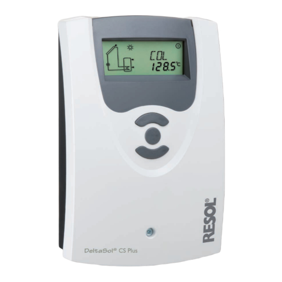
- Page 1 ® CS Plus DeltaSol version 1.10 Mounting Connection Application examples Operation Troubleshooting Thank you for buying this RESOL product. Manual Read this manual carefully to get the best perfomance from this unit. Please keep this manual carefully. www.resol.com...
- Page 2 Safety advice Information about the product Please pay attention to the following safety advice in order to avoid danger and Proper usage damage to people and property. The solar controller is designed for use in solar thermal systems and heating sys- tems in compliance with the technical data specified in this manual.
-
Page 3: Table Of Contents
Contents Installation ................... 5 1.1 Mounting ........................5 1.2 Electrical connection ....................5 1.3 VFD Grundfos Direct Sensor™ ................7 1.4 PWM outputs ........................7 1.5 Data communication / Bus ..................7 1.6 Terminal allocation in the different system layouts ..........8 Operation and function ..............46 2.1 Push buttons ....................... - Page 4 Power consumption: < 1 W (standby) • Housing with outstanding design Mode of operation: type 1.C.Y action • Extra-low power consumption Rated impulse voltage: 2.5 kV • HE pump control Data interface: RESOL VBus ® • Drainback option VBus ® current supply: 35 mA...
-
Page 5: Installation
Installation display WARNING! Electric shock! Opening the housing will expose live parts! Î Switch off power supply and disconnect the device from power supply before opening the housing! upper fastening Mounting cover push button The unit must only be installed •... - Page 6 The mains supply is to be carried out at the terminals: 19 = neutral conductor N de in Germany 100 ... 240 V~ 20 = conductor L 50-60 Hz IP 20 12 = protective conductor ⏚ 1 (1) A 240 V~ The temperature sensors (S1 up to S4) are to be connected to the following 1 (1) A 240 V~ terminals with either polarity:...
-
Page 7: Vfd Grundfos Direct Sensor
PWM outputs connection terminals The speed of a HE pump is adjusted through a PWM signal. In addition to con- The controller is equipped with a RESOL VBus for data transfer with and energy ® nection to the relay, the pump must be connected to one of the PWM outputs of supply to external modules. -
Page 8: Terminal Allocation In The Different System Layouts
Terminal allocation in the different system layouts System layout 1 The controller calculates the temperature difference between collector sensor If heat quantity measurement (OHQM) is activated, S4 and VFD are to be connect- S1 and store sensor S2. If the difference is larger than or identical to the adjusted ed as flow and return sensors respectively. - Page 9 Display Channels Channel Description Terminal Page INIT ODB initialisation active ODB filling time active STAB ODB stabilisation in progress Temperature collector Temperature store Temperature sensor 3 TSTT Temperatur store at the top Temperature sensor 4 Temperature flow sensor S1 / S4 / VFD Temperature return sensor S4 / VFD Temperature Grundfos Direct Sensor™...
-
Page 10: Channel Description
Adjustment Channels Channel Description Factory setting Page DTCO Cooling switch-on temperature difference 20.0 K [40.0 °Ra] DTCF Cooling switch-off temperature difference 15.0 K [30.0 °Ra] OSTC Option store cooling OHOL Option holiday cooling THOL Holiday cooling temperature 40 °C [110 °F] Option minimum limitation Minimum collector temperature 10 °C [50 °F]... - Page 11 System layout 2 The controller calculates the temperature difference between collector sensor adjusted switch-on temperature difference (DT3O), until the adjusted minimum S1 and store sensor S2. If the difference is larger than or identical to the adjusted (MN3O) and maximum (MX3O) temperature thresholds of the respective stores switch-on temperature difference (DT O), the solar pump will be operated by relay are reached.
-
Page 12: Display Channels
Display Channels Channel Description Terminal Page INIT ODB initialisation active ODB filling time active STAB ODB stabilisation in progress Temperature collector TST1 Temperature store 1 base TSTT Temperature store 1 at the top TST2 Temperature store 2 base Temperature flow sensor Temperature return sensor Temperature Grundfos Direct Sensor™... -
Page 13: Adjustment Channels
Adjustment Channels Channel Description Factory setting Page OSTC Option store cooling OHOL Option holiday cooling THOL Holiday cooling temperature 40 °C [110 °F] Option minimum limitation Minimum collector temperature 10 °C [50 °F] Option antifreeze Antifreeze temperature 4.0 °C [40.0 °F] O TC Option tube collector TCST... - Page 14 System-specific functions Pump speed control The following adjustments are used for the specific function in system layout 2. ∆T control for the heat exchange between 2 stores DT3S: Nominal temperature difference Adjustment range: 1.5 … 30.0 K [3.0 … 60.0 °Ra] DT3O: in steps of 0.5 K [1 °Ra] Switch-on temperature diff.
- Page 15 Minimum pump speed n2MN PUM2 Pump speed control Pump control type R2 Adjustment range: (10) 30 … 100 % Selection: OnOF, PULS, PSOL, PHEA in steps of 5 % Factory setting: OnOF Factory setting: 30 % With this parameter, the pump control type can be adjusted. A relative minimum pump speed can be allocated to the output R2 via the adjust- The following types can be selected: ment channel n2MN.
- Page 16 Maximum temperature limitation Minimum temperature limitation MX3O / MX3F: MN3O / MN3F: Maximum temperature limitation Minimum temperature limitation Adjustment range: 0.0 … 95.0 °C [30.0 … 200.0 °F] Adjustment range: 0.0 … 90.0 °C [30.0 … 190.0 °F] in steps of 0.5 °C [1.0 °F] in steps of 0.5 °C [1.0 °F] Factory setting: Factory setting (Arr = 2 only):...
- Page 17 System layout 3 The controller calculates the temperature difference between collector sensor (AH O) is reached. This function can optionally be combined with up to three S1 and store sensor S2. If the difference is larger than or identical to the adjusted adjustable time frames.
-
Page 18: S4 X Temperature Sensor
Display Channels Channel Description Terminal Page INIT ODB initialisation active ODB filling time active STAB ODB stabilisation in progress Temperature collector TSTB Temperature store 1 base TSTT Temperature store 1 at the top TDIS Thermal disinfection temperature Temperature sensor 4 Temperature flow sensor S1 / S4 / VFD Temperature return sensor... -
Page 19: Channel Description
Adjustment Channels Channel Description Factory setting Page Minimum collector temperature 10 °C [50 °F] Option antifreeze Antifreeze temperature 4.0 °C [40.0 °F] O TC Option tube collector TCST OTC starting time 07:00 TCEN OTC ending time 19:00 TCRU OTC runtime 30 s TCIN OTC standstill interval... - Page 20 System-specific functions The following functions are exclusively available in system layout 3. The corre- sponding channels will not be available in any other system layout. Thermostat function Afterheating Use of surplus AH F: energy Thermostat switch-off tem p. Adjustment range: 0.0 … 95.0 °C [30.0 … 200.0 °F] in steps of 0.5 °C [1.0 °F] Factory setting: 45.0 °C [120.0 °F]...
- Page 21 Thermal disinfection Reference sensor for the thermal disinfection function is S3! For thermal disinfection, the temperature at the reference sensor has to be mon- itored. This protection is ensured when, during the monitoring period, the disin- fection temperature is continuously exceeded for the entire disinfection period. If the thermal disinfection function is activated, the monitoring period starts as soon as the temperature at the reference sensor falls below the disinfection tem- OtD:...
- Page 22 System layout 4 The controller calculates the temperature differences between collector sensor S1 (S1MX / S2MX) are reached. The priority logic causes priority loading of the upper and store sensors S2 and S3. If the differences are larger than or identical to the ad- zone of the store, if possible.
-
Page 23: Tfl X* Temperature Flow Sensor
Display Channels Channel Description Terminal Page Temperature collector TSTB Temperature store 1 base TSTT Temperature store 1 at the top Temperature sensor 4 Temperature flow sensor S1 / S4 / VFD Temperature return sensor S4 / VFD Temperature Grundfos Direct Sensor™ Flow rate Grundfos Direct Sensor™... -
Page 24: Channel Description
Adjustment Channels Channel Description Factory setting Page OSTC Option store cooling OHOL Option holiday cooling THOL Holiday cooling temperature 40 °C [110 °F] Option minimum limitation Minimum collector temperature 10 °C [50 °F] Option antifreeze Antifreeze temperature 4.0 °C [40.0 °F] PRIO Priority Break time... - Page 25 System layout 5 The controller calculates the temperature differences between collector sensor S1 (S1MX / S2MX) are reached. The priority logic causes priority loading of store 1, if and store sensors S2 and S3. If the differences are larger than or identical to the possible.
-
Page 26: K [12.0 °Ra]
Display Channels Channel Description Terminal Page Temperature collector TST1 Temperature store 1 base TST2 Temperature store 2 base Temperature sensor 4 Temperature flow sensor S1 / S4 / VFD Temperature return sensor S4 / VFD Temperature Grundfos Direct Sensor™ Flow rate Grundfos Direct Sensor™ Pump speed relay R1 Operating hours R1 Operating hours R2... -
Page 27: Channel Description
Adjustment Channels Channel Description Factory setting Page OSTC Option store cooling OHOL Option holiday cooling THOL Holiday cooling temperature 40 °C [110 °F] Option minimum limitation Minimum collector temperature 10 °C [50 °F] Option antifreeze Antifreeze temperature 4.0 °C [40.0 °F] PRIO Priority Break time... - Page 28 System layout 6 The controller calculates the temperature differences between collector sensor ing of the selected store (PRIO), if possible. Loading both stores simultaneously is S1 and store sensors S2 and S3. If the differences are larger than or identical to possible as well (PRIO = 0).
-
Page 29: Psol
Display Channels Channel Description Terminal Page Temperature collector TST1 Temperature store 1 base TST2 Temperature store 2 base Temperature sensor 4 TSTT Temperature store at the top Temperature flow sensor S1 / S4 / VFD Temperature return sensor S4 / VFD Temperature Grundfos Direct Sensor™... -
Page 30: Channel Description
Adjustment Channels Channel Description Factory setting Page OSYC Option system cooling DTCO Cooling switch-on temperature difference 20.0 K [40.0 °Ra] DTCF Cooling switch-off temperature difference 15.0 K [30.0 °Ra] OSTC Option store cooling OHOL Option holiday cooling THOL Holiday cooling temperature 40 °C [110 °F] Option minimum limitation Minimum collector temperature... - Page 31 System layout 7 The controller calculates the temperature differences between the collector sen- Sensor S4 can optionally be used as reference sensor for the store emergency sors S1 and S3 and the store sensor S2. If the differences are larger than or identi- shutdown option (OSEM).
-
Page 32: C [140 °F]
Display Channels Channel Description Terminal Page COL1 Temperature collector 1 Temperature store COL2 Temperature collector 2 Temperature sensor 4 TSTT Temperature store at the top Temperatur Vorlaufsensor S4 / VFD Temperatur Rücklaufsensor S4 / VFD Temperatur Grundfos Direct Sensor™ Volumenstrom Grundfos Direct Sensor™ n1 % Pump speed R1 n2 %... -
Page 33: Channel Description
Adjustment Channels Channel Description Factory setting Page CMX2 Maximum temperature collector 2 110 °C [230 °F] OSYC Option system cooling DTCO Cooling switch-on temperature difference 20.0 K [40.0 °Ra] DTCF Cooling switch-off temperature difference 15.0 K [30.0 °Ra] OSTC Option store cooling OHOL Option holiday cooling THOL... - Page 34 System layout 8 The controller calculates the temperature difference between collector sensor perature difference (DT3O), until the adjusted minimum (MN3O) and maximum S1 and store sensor S2. If the difference is larger than or identical to the adjusted (MX3O) temperature thresholds of the fuel boiler and the store are reached. S3 can optionally be used as reference sensor for the store emergency shutdown switch-on temperature difference (DT O), the solar pump will be operated by re- lay 1, and the store will be loaded until the switch-off temperature difference (DT...
-
Page 35: C [200 °F]
Display Channels Channel Description Terminal Page INIT ODB initialisation active ODB filling time active STAB ODB stabilisation in progress Temperature collector TSTB Temperature store 1 base TSTT Temperature store 1 at the top Temperature flow sensor Temperature return sensor Temperature Grundfos Direct Sensor™ Flow rate Grundfos Direct Sensor™... -
Page 36: Channel Description
Adjustment Channels Channel Description Factory setting Page OSTC Option store cooling OHOL Option holiday cooling THOL Holiday cooling temperature 40 °C [110 °F] Option minimum limitation Minimum collector temperature 10 °C [50 °F] Option antifreeze Antifreeze temperature 4.0 °C [40.0 °F] O TC Option tube collector TCST... - Page 37 System-specific functions Pump speed control The following adjustments are used for the specific functions in system layout 8. ∆T control for afterheating by solid fuel boiler DT3S: Nominal temperature difference Adjustment range: 1.5 … 30.0 K [3.0 … 60.0 °Ra] in steps of 0.5 K [1 °Ra] DT3O: Factory setting: 10.0 K [20.0 °Ra]...
- Page 38 Minimum pump speed n2MN: PUM2 Minimum pump speed R2 Pump control type R2 Adjustment range: (10) 30 … 100 % Selection: OnOF, PULS, PSOL, PHEA in steps of 5 % Factory setting: OnOF Factory setting: 30 % With this parameter, the pump control type can be adjusted. A relative minimum pump speed can be allocated to the output R2 via the adjust- The following types can be selected: ment channel n2MN.
- Page 39 Maximum temperature limitation Minimum temperature limitation MN3O / MN3F: MX3O / MX3F: Maximum temperature limitation Minimum temperature limitation Adjustment range: 0.0 … 95.0 °C [30.0 … 200.0 °F] Adjustment range: 0.0 … 90.0 °C [30.0 … 190.0 °F] in steps of 0.5 °C [1 °F] in steps of 0.5 °C [1 °F] Factory setting: Factory setting (Arr = 8 only):...
- Page 40 System layout 9 The controller calculates the temperature difference between collector sensor A heating circuit return preheating will be operated by relay 2, if the temperature S1 and store sensor S2. If the difference is larger than or identical to the adjusted difference between sensors S3 and S4 is larger than or identical to the adjusted switch-on temperature difference (DT O), the solar pump will be operated by relay switch-on temperature difference (DT3O).
-
Page 41: Tfl X* Temperature Flow Sensor
Display Channels Channel Description Terminal Page INIT ODB initialisation active ODB filling time active STAB ODB stabilisation in progress Temperature collector TSTB Temperature store 1 base TSTT Temperature store 1 at the top Temperature flow sensor Temperature return sensor Temperature Grundfos Direct Sensor™ Flow rate Grundfos Direct Sensor™... -
Page 42: Channel Description
Adjustment Channels Channel Description Factory setting Page DTCF Cooling switch-off temperature difference 15.0 K [30.0 °Ra] OSTC Option store cooling OHOL Option holiday cooling THOL Holiday cooling temperature 40 °C [110 °F] Option minimum limitation Minimum collector temperature 10 °C [50 °F] Option antifreeze Antifreeze temperature 4.0 °C [40.0 °F]... - Page 43 System layout 10 The controller calculates the temperature difference between collector sensor out only if the store temperature is below the non-adjustable emergency shut- S1 and store sensor S2. If the difference is larger than or identical to the adjusted down of 95 °C [200 °F].
-
Page 44: Tfl X* Temperature Flow Sensor
Display Channels Channel Description Terminal Page Temperature collector Temperature store Temperature sensor 3 TSTT Temperature store at the top Temperature flow sensor S1 / S4 / VFD Temperature sensor 4 Temperature Grundfos Direct Sensor™ Flow rate Grundfos Direct Sensor™ Temperature return sensor S4 / VFD Pump speed relay R1 h P1... -
Page 45: Sen X* Vfd Allocation 2
Adjustment Channels Channel Description Factory setting Page TCRU OTC runtime 30 s TCIN OTC standstill interval 30 min Grundfos Direct Sensor™ OHQM Option heat quantity measurement VFD allocation FMAX Maximum flow 6.0 l/min MEDT Antifreeze type MED% Antifreeze concentration (only if MEDT = propylene or ethylene) 45 % MAN1 Manual operation R1... -
Page 46: Operation And Function
The System-Monitoring-Display consists of three blocks: channel display, tool Operation and function bar and system screen. Push buttons channel display forward (+) The system monitoring display consists of three blocks: channel display, tool (selection / ad- bar and system screen (active system layout). justment mode) The channel display consists of two lines. -
Page 47: Flashing Codes
System screen Flashing codes System screen flashing codes • Pumps are flashing when the corresponding relay is switched on • Sensor symbols are flashing if the corresponding sensor display channel is selected • Sensors are flashing quickly in the case of a sensor fault •... -
Page 48: Commissioning
Commissioning The commissioning menu consists of the following 8 channels: forward (+) (selection / adjustment mode) LANG backward (-) Language selection The three push buttons of the CS Plus controller Selection: dE, En, Fr, ES, It Factory setting: En Î Establish the power supply 1. - Page 49 If the system layout selection is changed later on, any previous adjustments which have been made in the other channels will be lost. Therefore, changing the system layout is always followed by a security enquiry. Only confirm the security enquiry if you are sure that you wish to change the system layout selection! Security enquiry: System layout selection...
- Page 50 In order to reduce the number of switching processes for high-efficiency pumps, the controller is equipped with a relay overrun function that automatically comes into effect when the speed control signal is not issued by the relay itself (PUM = PSOL or PHEA).
-
Page 51: Channel Overview
Channel overview Display channels Note: The displayed values and adjustment channels depend on which system layout, which options and functions have been selected. Only values and adjustment channels available for the individual settings selected will appear nMX, n1MX, n2MX in the menu. Maximum pump speed Indication of drainback time periods Adjustment range: (10) 30 …... - Page 52 Indication of collector temperatures Indicates the current temperature of the corresponding additional sensor (without control function). • S3 : temperature at sensor 3 • S4 : temperature at sensor 4 • VFD : temperature at the Grundfos Direct Sensor™ COL, COL1, COL2 Note: Collector temperature S3 and S4 will only be indicated if the temperature sensors are connected.
- Page 53 Indication of current pump speed n %, n1 %, n2 % CDIS Current pump speed Countdown of monitoring period Display range: 30 … 100 % Display range: 0 … 30:0 … 24 (dd:hh) Indicates the current pump speed of the corresponding pump. If the thermal disinfection option (OTD) is activated and the monitoring period is in progress, the remaining monitoring time will be displayed as CDIS (in days and •...
-
Page 54: Adjustment Channels
Adjustment channels System layout selection TIME Indicates the current time. System layout selection. Î Press button 3 for 2 s to adjust the hours Adjustment range: 1 … 10 Î Set the hours by pressing buttons 1 and 2 Factory setting: 1 Î... - Page 55 Note: The switch-on temperature difference must be at least 0.5 K [1 °Ra] high- er than the switch-off temperature difference. RIS / RIS1 / RIS2 / RIS3 Rise Adjustment range: 1 … 20 K [2 … 40 °Ra] in steps of 1 K [2 °Ra] DT F / DT1F / DT2F / DT3F Factory setting: 2 K [4 °Ra] Switch-off temperature diff.
- Page 56 Adjustment for standard pump with speed control • PULS (pulse packet control via semiconductor relay) Adjustment for high efficiency pump (HE pump) • PSOL (PWM profile for a high-efficiency solar pump) • PHEA (PWM profile for a high-efficiency heating pump) nMX,n1MX, n2MX Maximum pump speed In order to reduce the number of switching processes for high-efficiency pumps,...
- Page 57 Store emergency shutdown option Note: If the drainback option ODB is activated, the adjustment range of EM is changed to 80 … 120 °C [170 … 250 °F]. The factory setting in that case is 95 °C [200 °F]. OSEM WARNING! Danger of injury and system damage through pressure surges!
- Page 58 DTCO CMX / CMX1 / CMX2 Switch-on temperature diff. Maximum collector temp. Adjustment range: 1.0 … 30.0 K [2.0 … 60.0 °Ra] Adjustment range: 70 … 160 °C [150 … 320 °F] in steps of 0.5 K [1 °Ra] in steps of 1 °C [1 °F] Factory setting: 20.0 K [40.0 °Ra] Factory setting: 110 °C [230 °F] When the system cooling function is activated, the controller aims to keep the...
- Page 59 Store cooling function If no DHW consumption is expected for a longer period of time, the additional holiday cooling option OHOL can be activated in order to extend the store cool- ing function. The adjustable temperature THOL then replaces the maximum store temperature (S MX / S1MX) as a switch-off temperature for the store cooling function.
- Page 60 OCF / OCF1 / OCF2 PRIO Antifreeze function Loading priority Adjustment range: OFF / ON Adjustment range: SE 1, SE 2, Su 1, Su 2, 0, 1, 2 Factory setting: OFF Factory setting: Arr 4: 2; Arr 5, 6: 1 If a multi-store system layout has been chosen, the priority logic determines how the heat is divided between the stores.
- Page 61 Spreaded loading temperature difference As soon as the switch-on condition of the priority store is fulfilled, it will be loaded. (only available if PRIO is set to SE 1 or SE 2) If the switch-on condition of the priority store is not fulfilled, loading of the second store will be continued.
- Page 62 WARNING! Danger of injury and system damage through pressure surges! If a drainback system is filled due to the tube collector function and the heat transfer medium enters very hot collectors, pressure surges can occur. TCEN Î If a pressure-less drainback system is used, TCST and Tube collector function TCEN must be adjusted such that the system will not ending time...
- Page 63 Heat quantity measurement with a fixed flow rate value Heat quantity measurement is possible on Arr. 1, 3, 4, 5 and 10 if a flowmeter is used. To enable heat quantity measurement, proceed as follows: Î Read the flow rate (l/min) from the flowmeter at maximum pump speed and adjust it in the FMAX channel.
- Page 64 MED% Antifreeze ratio Drainback option in Vol-% Adjustment range: OFF / ON (MED% is hidden when MEDT 0 or 3 is used.) Factory setting: OFF Adjustment range: 20 … 70 % Note: in steps of 1 % When the drainback option ODB is activated, the cooling functions Factory setting: 45 % OCC, OSYC and OSTC as well as the antifreeze function OCF are Note:...
- Page 65 Filling time Operating mode tFLL MAN1 / MAN2 Filling time Operating mode Adjustment range: 1.0 … 30.0 min Adjustment range: OFF, Auto, ON in steps of 0.5 min Factory setting: Auto Factory setting: 5.0 min For control and service work, the operating mode of the controller can be manual- The filling time can be adjusted using the parameter tFLL.
- Page 66 Unit UNIT Temperature unit selection Selection: °C, °F Factory setting: °C In this adjustment channel, the display unit for temperatures and temperature differences can be chosen. The unit can be switched between °C / K and °F / °Ra during operation. Temperatures and temperature differences in °F and °Ra are displayed without units.
-
Page 67: Troubleshooting
Troubleshooting fuse On the display the symbols appear. Made in Germany 100 ... 240 V~ DeltaSol CS Plus ® Sensor defect. An error code instead of a temperature is displayed 50-60 Hz IP 20 PWM 1/2 in the sensor display channel. 1 (1) A 240 V~ 888.8 - 88.8... -
Page 68: Various
Display off. Pump starts up very late Switch-on temperature difference Check the power supply. Is it disconnected? ∆Ton to large? Change ∆Ton and ∆Toff corre- spondingly. Check the supply line and recon- The fuse of the controller could be blown. It can be replaced after the nect it. - Page 69 Stores cool down at night Control the non-return valve in Further pumps which are connect- Collector circuit pump runs during Check controller: warm water circulation - o.k. ed to the solar store must also be the night? Manual operation active? checked.
-
Page 70: Accessories
RESOL SP10. Large Display GA3 The RESOL Large Display GA3 is designed for simple connection to RESOL con- trollers via the RESOL VBus . It is used for visualizing the data issued by the con- ®... - Page 71 Thus, controller access and data charting can graphic display. Transfer data with an SD memory card or use the LAN interface to be effected from every workstation of the network. A full version of the RESOL view and process data on your PC.
- Page 72 This mounting- and operation manual including all parts is copyrighted. Anoth- some examples. They can only be used at your own risk. No liability is assumed for er use outside the copyright requires the approval of RESOL – Elektronische incorrect, incomplete or false information and / or the resulting damages.
Need help?
Do you have a question about the DeltaSol CS Plus and is the answer not in the manual?
Questions and answers