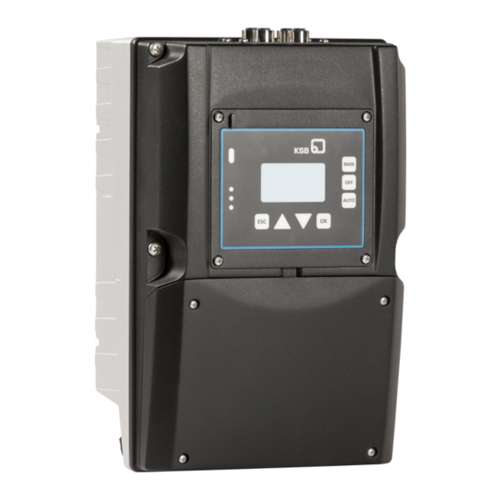
KSB PumpDrive 2 Eco Installation & Operating Manual
Self-cooling, motor-independent
frequency inverter
Hide thumbs
Also See for PumpDrive 2 Eco:
- Installation & operating manual (213 pages) ,
- Application manual (50 pages) ,
- Supplementary operating manual (20 pages)

Related Manuals for KSB PumpDrive 2 Eco


Summary of Contents for KSB PumpDrive 2 Eco
- Page 1 Self-cooling, motor-independent frequency inverter PumpDrive 2 Eco Installation/Operating Manual...
- Page 2 All rights reserved. The contents provided herein must neither be distributed, copied, reproduced, edited or processed for any other purpose, nor otherwise transmitted, published or made available to a third party without the manufacturer's express written consent. Subject to technical modification without prior notice. © KSB SE & Co. KGaA, Frankenthal 29/03/2018...
-
Page 3: Table Of Contents
Electrical connection.......................... 27 Operation.............................. 45 Standard control panel .......................... 45 6.1.1 Display .............................. 45 6.1.2 Main screen ............................ 48 6.1.3 Settings menu ............................ 49 6.1.4 Service interface and LED traffic light function................ 52 Commissioning/Shutdown ........................ 53 Control point concept ............................ 53 PumpDrive 2 Eco 3 of 172... - Page 4 Automatic motor adaptation (AMA) of frequency inverter................ 56 7.4.1 Automatic motor adaptation (AMA) of frequency inverter for asynchronous motors.... 56 7.4.2 Automatic motor adaptation (AMA) of frequency inverter for KSB SuPremE motors .... 57 Entering the setpoint ............................. 58 Pump operation.............................. 59 7.6.1 Single-pump operation........................ 59 7.6.2...
-
Page 5: Glossary
Proprietary CAN bus that is used in dual and multiple pump configurations for facilitating communication among the frequency inverters. The KSB device bus cannot be used for external communication or for communication with the KSB local bus (PumpDrive 1). Pump... -
Page 6: General
The serial number uniquely describes the product and is used as identification in all further business processes. In the event of damage, immediately contact your nearest KSB service centre to maintain the right to claim under warranty. 1.2 Target group This operating manual is aimed at the target group of trained and qualified specialist technical personnel. -
Page 7: Safety
▪ The product must not be used in potentially explosive atmospheres. PumpDrive 2 Eco 7 of 172... -
Page 8: Personnel Qualification And Training
▪ Carry out work on the product during standstill only. ▪ As soon as the work has been completed, re-install and re-activate any safety- relevant devices and protective devices. Before returning the product to service, observe all instructions on commissioning. PumpDrive 2 Eco 8 of 172... -
Page 9: Unauthorised Modes Of Operation
The software has been specially created for this product and thoroughly tested. It is not allowed to make any changes or additions to the software or parts of the software. Software updates supplied by KSB are excluded from this rule. 2.11 Electromagnetic compatibility (EMC) -
Page 10: Line Harmonics Requirements
▪ EN 61000-4-5: Electromagnetic compatibility (EMC) – Part 4-5: Testing and measurement techniques – Surge immunity test ▪ EN 61000-4-6: Electromagnetic compatibility (EMC) – Part 4-6: Testing and measurement techniques – Immunity to conducted disturbances, induced by radio-frequency fields PumpDrive 2 Eco 10 of 172... -
Page 11: Transport/Temporary Storage/Disposal
1. On transfer of goods, check each packaging unit for damage. 2. In the event of in-transit damage, assess the exact damage, document it and notify KSB or the supplying dealer (as applicable) and the insurer about the damage in writing immediately. -
Page 12: Storage
CAUTION Damage during storage by humidity, dirt or vermin Corrosion/contamination of the control unit! ▷ For outdoor storage cover the (packed or unpacked) control unit and accessories with water-proof material. PumpDrive 2 Eco 12 of 172... -
Page 13: Disposal/Recycling
- Line chokes with copper windings - Copper lines for internal wiring 3. Dispose of materials in accordance with local regulations or in another controlled manner. PCBs, power electronics, capacitors and electronic components are all special waste. PumpDrive 2 Eco 13 of 172... -
Page 14: Description
Table 8: Designation example Position P D R V 2 Table 9: Key to the designation Position Code Description Generation PDRV2 2. PumpDrive generation ✘ ✘ Variant PumpDrive 2 Eco ✘ PumpDrive 2 ✘ 8-13 Power 000K37 = 0,37 kW ✘ ✘ 000K55 = 0,55 kW ✘ ✘ 000K75 = 0,75 kW ✘... - Page 15 Profinet ✘ Optional component 1 None ✘ ✘ I/O extension board ✘ Optional component 2 None ✘ ✘ Bluetooth module ✘ ✘ Optional component 3 None ✘ ✘ Master switch ✘ Consult the manufacturer. PumpDrive 2 Eco 15 of 172...
-
Page 16: Name Plate
PumpDrive type code KSB order number Pump designation Date of manufacture 4.4 Power range and sizes Table 10: Power range for 2-pole (3000 rpm), 4-pole (1500 rpm) and 6-pole (1000) asynchronous motors and KSB SuPremE Size Nominal electrical power Nominal output current Mains input current... -
Page 17: Technical Data
TN-S, TN-CS, TN-C, TT and IT mains (to IEC/EN 60364) Output data Frequency inverter output frequency 0 - 70 Hz for asynchronous motors 0 - 140 Hz for KSB SuPremE PWM carrier frequency Range: 2 - 8 kHz Factory setting: 4 kHz Phase rate of rise dv/dt 5000 V/µs max. - Page 18 DC: Max. 30 V DC/2 A PWM carrier frequency Power derating for increased carrier frequency Sizes A, B and C (at PWM carrier frequency > 4 kHz): × (1 - [f - 4 kHz] × 2.5 %) Nominal motor current (PWM) Nominal motor current PumpDrive 2 Eco 18 of 172...
-
Page 19: Dimensions And Weights
C .. 005K50.. 5,5 330 255 185 219 205 401 255 185 219 387 M6 × 12 .. 007K50.. 7,5 0011K00.. The dimensions provided refer to PumpDrive including the wall-mounting brackets. Without motor adapter PumpDrive 2 Eco 19 of 172... -
Page 20: Mounting Options
▪ Cabinet mounting The installation kit required for the cabinet-mounted model is included in the scope of supply. Installation kits for subsequent conversion to cabinet mounting for existing pump systems are available as accessories. PumpDrive 2 Eco 20 of 172... -
Page 21: Installation At Site
5.3.2 Wall/control cabinet mounting The wall-mounted model is supplied with the installation kit required for wall mounting as standard. Installation kits for subsequent conversion to the wall mounting configuration for existing pump systems are available from KSB. PumpDrive 2 Eco 21 of 172... -
Page 22: Electrical Connection
WARNING Direct connection between power supply and motor connection (bypass) Damage to the frequency inverter! ▷ Never establish a direct connection between the power supply and motor connection (bypass) of the frequency inverter. PumpDrive 2 Eco 22 of 172... -
Page 23: Information For Planning The System
AC1 duty rating; the rated current values of the frequency inverters used are added and the result is increased by 15 %. Motor connection cable Shielded cables must be used as motor connection cables. Control cable Shielded cables must be used as control cables. PumpDrive 2 Eco 23 of 172... - Page 24 Impairment of protection provided by enclosure when cable diameters other than those specified are used. Observe the information on the use of line chokes provided in the Accessories section. PumpDrive 2 Eco 24 of 172...
- Page 25 Maintain a minimum distance of 0.3 metres between the cabling and power components as well as other cabling in the control cabinet. Connecting cables Use different earth bus bars for the control cable and power/motor connection cable. PumpDrive 2 Eco 25 of 172...
- Page 26 The scope of DIN EN 61000-3-2 must be heeded. Appropriate line chokes are available from KSB. (ð Section 11.2.7, Page 164) 5.4.2.6 Output filter The maximum cable lengths must be maintained in order to meet RFI suppression requirements to EN 55011.
-
Page 27: Electrical Connection
1. The protective cover for connecting the power and motor connection cables is push fit. Before connecting the power and motor connection cables, carefully pry open the protective cover using a wide screwdriver. Fig. 11: Removing the protective cover 2. Remove the protective cover. PumpDrive 2 Eco 27 of 172... - Page 28 Fig. 13: Overview of terminal strips for 400 V/ 3~ variant with 2 relays Mains power supply and motor Control cables connection 230 V/ 1~ variant LINE MOTOR PE U MOTOR Fig. 14: Overview of terminal strips for 230 V/ 1~ variant Mains power supply and motor Control cables connection PumpDrive 2 Eco 28 of 172...
- Page 29 In the event of a short circuit in the winding (short circuit between phase and PTC), a fuse trips and prevents carryover of low voltages to the low-voltage level. In the case of a fault or malfunction, this fuse can only be replaced by KSB service personnel.
- Page 30 L1 L2 L3 P TC MOTOR Fig. 17: Establishing the mains power supply and motor connections, size B ① Mains connection ② Motor connection ③ PTC connection ④ Braking resistor ⑤ Motor PTC ⑥ Jumper for IT mains PumpDrive 2 Eco 30 of 172...
- Page 31 Jumper in IT mains If the frequency inverter is to be used in an IT mains, the relevant IT mains jumpers (See Fig. "Establishing the mains power supply and motor connections") must be removed. PumpDrive 2 Eco 31 of 172...
- Page 32 3. Close the opening in the heat sink using the kit accompanying the frequency inverter (comprising a cover, gasket and bolts/screws). NOTE IP55 enclosure protection as specified in the technical data is only provided if the cover has been fitted properly. PumpDrive 2 Eco 32 of 172...
- Page 33 5 Installation at Site 5.4.3.3.2 Retrofitting a frequency inverter for a KSB SuPremE B2 motor (for sizes C only) The heat sink is closed with a plug. The following steps must be carried out to retrofit for a KSB SuPremE B2 motor.
- Page 34 5. Connect the motor cables as described. Fig. 25: Inserting motor cables 6. Connect the PTC cables that are supplied as standard with the KSB SuPremE B2 motor. 7. Close the frequency inverter with the protective cover and the housing cover.
- Page 35 5 Installation at Site Fig. 28: M12 module C, D Connection for dual pump configurations (KSB device bus) Connection for PumpMeter (Modbus) Connector for the bus cable crosslink (Modbus) ▪ Can be retrofitted ▪ Internal T-connector (bus looped through) [uninterruptible even in the event of a frequency inverter power failure] ▪...
- Page 36 Fig. 31: Securing the M12 module CAUTION Incorrect assembly Impairment of protection provided by the enclosure (protection may be compromised)! ▷ Cover unused M12 sockets of the M12 module with a cap (included in the scope of supply). PumpDrive 2 Eco 36 of 172...
- Page 37 (colour: light purple, connector: angled, connector: angled) Connection for dual pump configuration, PumpDrive No. 2 NOTE Terminating resistors (refer to KSB accessories) that can be connected to the unassigned M12 connector (C or D) at the M12 module are required for the bus terminator.
- Page 38 0 V 0 V White Input (4 - 20 mA) Grey Vent opening Table 20: Pin assignment, M12 module, input C/D Conductor colour coding M12 socket C and D assignment Shielding Black CAN GND White CAN H PumpDrive 2 Eco 38 of 172...
- Page 39 ▪ Pre-configured cables (ð Section 11.2, Page 153) ▪ Connector for self assembly (ð Section 11.2, Page 153) Installing the field bus module The field bus module can be fitted in an available slot of the frequency inverter. PumpDrive 2 Eco 39 of 172...
- Page 40 Fig. 38: Securing the field bus module CAUTION Incorrect assembly Impairment of protection provided by the enclosure (protection may be compromised)! ▷ Cover unused M12 sockets with a cap (included in the scope of supply). PumpDrive 2 Eco 40 of 172...
- Page 41 The frequency inverter is reset when a field bus module is replaced or retrofitted. Menu 3-12 for setting the parameters of the field bus module is then enabled. 5.4.3.7 Connecting the control cable Fig. 40: Structure of electric cable Wire end sleeve Core Cable PumpDrive 2 Eco 41 of 172...
- Page 42 Relay, reference (COM) +24 V +24 V DC voltage source NOTE The new frequency inverter generation is equipped with a second relay. Impairment of protection provided by enclosure when cable diameters other than those specified are used. PumpDrive 2 Eco 42 of 172...
- Page 43 If the internal 24 V source is used, the internal GND must also be connected to the electrically isolated DICOM ground of the digital inputs. A wire jumper can be used between GND and DICOM for this purpose. PumpDrive 2 Eco 43 of 172...
- Page 44 3. Position the standard control panel and fasten with screws. Changing the installation position of the control panel Table 25: Possible installation positions for the control panel Standard Rotated 180° The standard control panel can be rotated 180 degrees if required. PumpDrive 2 Eco 44 of 172...
-
Page 45: Operation
Displays information on frequency inverter operation Operating keys Toggling operating modes Navigation keys Navigation and parameter setting 6.1.1 Display AUTO 1/min °C bar Fig. 42: Main screen (example) Operating point display Type of control Display of the current operating mode PumpDrive 2 Eco 45 of 172... - Page 46 ▪ The wrench icon shows that you have logged in as a customer. Parameter value example: Setpoint (Closed-loop Control) Message example: Dry running (E13): ▪ A message is identified by the letter E (Error) and a unique number. AUTO 1/min Message example: Dry running PumpDrive 2 Eco 46 of 172...
- Page 47 ▪ Press the OK or ESC key to go from digit to digit. Press the ESC key to go back. Changes are rejected. Pressing the OK key for the right-hand digit takes you back to the main screen. PumpDrive 2 Eco 47 of 172...
-
Page 48: Main Screen
Fig. 43: Selecting and displaying operating values on the main screen Parameter number for speed (1-2-1-1) Current speed [rpm] Parameter number for motor input power (1-2-1-2) Current power input of motor in kW Parameter number for motor current (1-2-1-5) Current motor current in A PumpDrive 2 Eco 48 of 172... -
Page 49: Settings Menu
The parameter numbers identify the navigation path, which helps you find a particular parameter quickly and easily. The first digit of the parameter number indicates the first menu level, which is called up directly via the four menu keys. PumpDrive 2 Eco 49 of 172... - Page 50 Pending Messages menu. All current messages can be displayed in the Diagnosis menu under Pending Messages (2-1). Active warnings and alerts can also be connected to the relay outputs. PumpDrive 2 Eco 50 of 172...
- Page 51 The MAN, OFF, AUTO and FUNC keys are locked without a valid login (customer). Locking operating keys The operating keys of the control panel can be locked via the 3-1-2-2 parameter to prevent unauthorised operation or unauthorised acknowledgement of alerts. PumpDrive 2 Eco 51 of 172...
-
Page 52: Service Interface And Led Traffic Light Function
LED traffic light function The LED traffic light function provides information about the current PumpDrive operating status. Table 35: LED description Description One or more than one alert is active Amber One or more than one warning is active Steady light: Trouble-free operation Green PumpDrive 2 Eco 52 of 172... -
Page 53: Commissioning/Shutdown
7.2 Setting motor parameters The motor parameters are typically preset at the factory. The factory default motor parameters must be compared with the data provided on the motor name plate and adjusted, if required. PumpDrive 2 Eco 53 of 172... -
Page 54: Motor Control Method
7.3 Motor control method The frequency inverter gives you a choice of several motor control methods: ▪ Vector control method for the KSB SuPremE motor ▪ Vector control method for the asynchronous motor ▪ V/f control method for the asynchronous motor The V/f control method can be selected for basic applications. - Page 55 0,0...100,00 % 3-2-1-3 Data points for the V/f characteristic 3-3-2-8 V/f Voltage 4 0,0...100,00 % 3-2-1-2 Data points for the V/f characteristic 3-3-2-9 V/f Frequency 4 0,0...100,00 % 3-2-1-3 Data points for the V/f characteristic PumpDrive 2 Eco 55 of 172...
-
Page 56: Automatic Motor Adaptation (Ama) Of Frequency Inverter
NOTE If the extended motor data cannot be determined using the AMA option, an AMA Fault alert is output. In this scenario, the extended motor data is not saved and AMA must be restarted. PumpDrive 2 Eco 56 of 172... -
Page 57: Automatic Motor Adaptation (Ama) Of Frequency Inverter For Ksb Supreme Motors
7.4.2 Automatic motor adaptation (AMA) of frequency inverter for KSB SuPremE motors Automatic motor adaptation for the KSB SuPremE motor is started using the Update Motor Parameters (3-3-4-1) parameter. Using the nominal motor data as a basis, the extended motor data is determined which ensures very good control of the KSB SuPremE motor. -
Page 58: Entering The Setpoint
SuPremE motor variant currently selected NOTE If the extended motor data for the KSB SuPremE motor cannot be determined, a No Matching Motor Data Available alert is output. The name plate data of the KSB SuPremE motor should be checked and verified. -
Page 59: Pump Operation
(Open-loop Control) parameter 1-3-3 or via an analog input . The frequency inverter starts in automatic mode if digital input 1 is supplied with +24 V DC (terminal strip C2/C1) or the system start is activated via the System Start / Stop parameter (1-3-1). PumpDrive 2 Eco 59 of 172... - Page 60 Fig. 47: Terminal wiring diagram, open-loop control mode, for variant with 1 relay (dashed line = optional) Start / Stop External setpoint signal Signal relay 1 Digital enable input Ground for digital inputs NOTE The new frequency inverter generation is equipped with a second relay. PumpDrive 2 Eco 60 of 172...
- Page 61 3-8-1-4 Analog Input 1 Upper Limit Minimum to maximum 100,00 limit of measuring range 1-3-1 System Start / Stop 0 = Stop 0 = Stop This function is used to start the system. PumpDrive 2 Eco 61 of 172...
- Page 62 Based on the current control deviation, a new control variable is calculated that is implemented as the new speed for the drive. PumpDrive 2 Eco 62 of 172...
- Page 63 The control direction of the controller is implicitly defined by the type of control selected. PumpDrive 2 Eco 63 of 172...
- Page 64 (3-6-4-8) is used to define the maximum differential gain, which will help limit the effect of measurement noise on the control value. Decreasing the limitation value restricts the influence of the differential constant at high frequencies, and the influence of measurement noise can be suppressed. PumpDrive 2 Eco 64 of 172...
- Page 65 Especially when very slow processes are involved, such as those of temperature control, a sufficiently long test sequence must be ensured via this value. The duration of determining the controller parameters automatically directly relates to the time specified here. PumpDrive 2 Eco 65 of 172...
- Page 66 Fig. 50: Terminal wiring diagram, closed-loop control mode, for variant with 1 relay (dashed line = optional) Start/stop 2 Feedback value transmitter Signal relay 1 PumpDrive 2 Eco 66 of 172...
- Page 67 Control) is selected. 3-11-2-1 Minimum Pressure 0,00 -1,00 bar Minimum limit of measuring range 3-11-2-2 Maximum Pressure 10,0 1000,0 bar Maximum limit of measuring range 3-11-2-3 Pressure Unit Configurable unit for pressure 1 PumpDrive 2 Eco 67 of 172...
- Page 68 (refer to parameter 3-11). If the value range or unit is subsequently changed, all dependent parameters must be checked for correctness again. PumpDrive 2 Eco 68 of 172...
- Page 69 (dashed line = optional) Start/stop 2 External setpoint signal Signal relay 1 Digital enable input Ground for digital inputs Feedback value transmitter NOTE The new frequency inverter generation is equipped with a second relay. PumpDrive 2 Eco 69 of 172...
- Page 70 10,0 1000,0 bar Maximum limit of measuring range 3-11-2-3 Pressure Unit Configurable unit for pressure 1 3-8-1-1 Analog Input 1 Signal 1 = 4-20 mA 0 = OFF Sensor signal at analog input 1 PumpDrive 2 Eco 70 of 172...
- Page 71 The response time of the system refers to the time that lapses after a change in speed until the flow rate exhibits almost no change at all. PumpDrive 2 Eco 71 of 172...
-
Page 72: Multiple Pump Configuration
The number of running pumps is defined via the Maximum Number of Pumps Running parameter (3-7-2). The speed is specified using the Control Value (Open-loop Control) parameter (1-3-3) (ð Section 7.6.1.1.2, Page 62) or via an analog input (ð Section 7.6.1.1.1, Page 60) . PumpDrive 2 Eco 72 of 172... - Page 73 If the master control device fails and a redundant master control device assumes its tasks, a temporary drop in pressure can occur. The maximum number of pumps running simultaneously is limited via the Maximum Number of Pumps Running parameter (3-7-2). PumpDrive 2 Eco 73 of 172...
- Page 74 % of maximum flow rate Q6. Switching limits for starting additional pumps are derived from this value. 3-7-3-6 KSB PumpDynamicControl 1…100 % 30 % Shift between energy-efficient (0 %) and dynamic operating mode (100 %) PumpDrive 2 Eco 74 of 172...
- Page 75 Fig. 54: Switching limits of a running pump in a multiple pump system Characteristic head curve of a running pump Characteristic head curve of two running pumps Stop limits: Stopping a running pump Start limits: Starting the second pump PumpDrive 2 Eco 75 of 172...
- Page 76 Characteristic head curve of two running pumps Stop limits: Stopping the second pump Start limits: Starting the third pump Arrows Effective direction of the switching limits Coloured area Operating range of two running pumps PumpDrive 2 Eco 76 of 172...
- Page 77 (3-7-4-2). When the Runtime with Time of Day setting has been selected, the changeover takes place at the time set (3-7-4-3) only if the pump has run for at least the defined runtime. If the pump is stopped, the runtime for this pump is reset. PumpDrive 2 Eco 77 of 172...
-
Page 78: Application Functions
Fig. 56: Characteristic head curve with seven data points and the relevant parameters Flow rate Q , i.e. parameter (3-4-3-1), is always zero. Flow rate Q6 (3-4-3-7) describes the end of the characteristic curves and also represents the maximum permissible flow rate of the pump. PumpDrive 2 Eco 78 of 172... - Page 79 Minimum to maximum flow rate Pump-specific 3-4-3-16 Head H_0 00,00...1000,00 Pump-specific 3-4-3-17 Head H_1 00,00...1000,00 Pump-specific 3-4-3-18 Head H_2 00,00...1000,00 Pump-specific 3-4-3-19 Head H_3 00,00...1000,00 Pump-specific 3-4-3-20 Head H_4 00,00...1000,00 Pump-specific 3-4-3-21 Head H_5 00,00...1000,00 Pump-specific PumpDrive 2 Eco 79 of 172...
-
Page 80: Protective Functions
5 %, the partially self-acknowledging Overcurrent alert is output that causes the motor to be stopped. The drive remains disabled as long as this event is active. The Motor Disabled status is displayed on the control panel. PumpDrive 2 Eco 80 of 172... - Page 81 7.7.2.6 Broken wire detection (live zero) The control system monitors all analog inputs at which a sensor has already been detected or for which a sensor has been permanently set for broken wire (live zero). PumpDrive 2 Eco 81 of 172...
- Page 82 If the mean value is exceeded or undershot, the control system overcomes the resonance range along the motor protection ramp. PumpDrive 2 Eco 82 of 172...
- Page 83 Operating point monitoring will only function properly if the Inside Pipe Diameters at Discharge Pressure Measuring Points (3-5-2-1 and 3-5-2-2) parameters have been entered. 3-4-3-30 3-4-3-31 Fig. 58: Head / flow rate diagram Permissible operating range Nominal speed Minimum speed Low flow limit Overload limit PumpDrive 2 Eco 83 of 172...
- Page 84 The frequency inverter performs a functional check run when a specific time has been reached. If the function is activated, the idle period of the pump must first have passed, at which point the functional check run is delayed until a specific configurable time is reached. PumpDrive 2 Eco 84 of 172...
- Page 85 (3-9-8-1). The characteristic curves are entered as described in (ð Section 7.7.1, Page 78) . If no pressure sensors are installed close to the pump for improving flow rate estimation accuracy, a monotonically increasing power curve is required. PumpDrive 2 Eco 85 of 172...
- Page 86 Table 65: Flow rate estimation parameters (parameterisation using the Service Tool) Parameter Description Possible settings Factory setting 3-9-8-1 Flow rate estimation 1 = ON 0 = OFF 3-5-2-1 Pipe Diameter_Suction Pressure 0...1000 mm 0,0 mm Measuring Point PumpDrive 2 Eco 86 of 172...
-
Page 87: Energy Optimisation
Piping with diagram of pressure losses Consumer with diagram of inlet pressure The discharge pressure of the pump (1) can be used in open piping systems to achieve an almost constant pressure upstream of the consumer (3). PumpDrive 2 Eco 87 of 172... - Page 88 To this end, the Dynamic Pressure Compensation Method parameter (3-9-3-1) is set to Flow Rate. The following diagram shows the setpoint compensation curve (solid line) as a function of the flow rate and relevant parameters. PumpDrive 2 Eco 88 of 172...
- Page 89 To this end, the Dynamic Pressure Compensation Method parameter (3-9-3-1) is set to Speed. The following diagram shows the setpoint compensation curve (solid line) as a function of the speed and relevant parameters. PumpDrive 2 Eco 89 of 172...
- Page 90 3-9-3-2 or 3-9-3-3 Minimum Setpoint Compensation Minimum to maximum limit of Dependent on the unit 3-9-3-5 Minimum setpoint compensation for measuring range opening the swing check valve in the case of low pump flow rates. PumpDrive 2 Eco 90 of 172...
- Page 91 Dynamic Pressure Compensation Method (3-9-3-1) parameter has been set to Speed. 3-9-3-2 Fig. 66: Setpoint compensation curve for dynamic pressure compensation based on flow rate Flow rate independent setpoint Setpoint Compensation Compensated setpoint PumpDrive 2 Eco 91 of 172...
- Page 92 Sleep mode only takes effect in closed-loop control mode. In multiple pump systems, sleep mode only takes effect if just one pump is running. Sleep mode is activated via parameter (3-9-4-1). PumpDrive 2 Eco 92 of 172...
- Page 93 Pressure drops as soon as fluid is withdrawn. If the configurable limit value for the Maximum Control Deviation for Restart (3-9-4-5) is achieved, the pump starts up again (t3). NOTE In a multiple pump system, starting of an additional pump cancels the stop attempt. PumpDrive 2 Eco 93 of 172...
-
Page 94: Ramps
Starting and stopping take place via speed ramps. A distinction is made between a start ramp and a stop ramp. The ramps are defined via parameters 3-3-5-1, 3-3-5-2 and 3-2-2-2. In open-loop control mode, the start ramp is left when the control value PumpDrive 2 Eco 94 of 172... - Page 95 If a speed change curve is flatter than the operating ramp, no limitation occurs. Parameters 3-2-2-2 and 3-3-5-3 are used for defining the operating ramp. PumpDrive 2 Eco 95 of 172...
- Page 96 Pressure (3-11-2-2) parameters. Example 2 Control targets constant temperature: The Type of Control parameter (3-6-1) is set to Temperature (Heating). Accordingly, control range Δx is limited by the Minimum Temperature (3-11-4-1) and Maximum Temperature (3-11-4-2) parameters. PumpDrive 2 Eco 96 of 172...
-
Page 97: Motor Standstill Heater
Factory setting 3-2-5-1 Motor Standstill Heater ▪ 0 = OFF Heating the motor via the motor windings ▪ 1 = ON 3-2-5-2 Heating Current 0,00…50,00 20,00 Heating current in % of nominal motor current PumpDrive 2 Eco 97 of 172... -
Page 98: Device Functions
PumpMeter Communication warning will be output and none of the parameters already transmitted will be accepted. As motor data can also be changed by the read process, PumpDrive 2 Eco 98 of 172... -
Page 99: Date And Time
Current CET Date Setting the date 3-1-4-2 Set Time 00:00…23:59 Current CET Time Setting the time of day 3-1-4-3 Time Format ▪ AM ▪ PM Selecting the format for displaying the time ▪ 24h PumpDrive 2 Eco 99 of 172... -
Page 100: Digital And Analog Inputs/Digital And Analog Outputs
▪ Reset alert ▪ Output control of analog input ▪ Process an external message (e.g. door open – response: pump off) ▪ Toggle OFF/Automatic/Fixed speed/External OFF ▪ Pump changeover ▪ Start functional check run PumpDrive 2 Eco 100 of 172... - Page 101 NOTE Requirements for the Digital Potentiometer Manual function must be specified at every control device, not just at the active master control device. PumpDrive 2 Eco 101 of 172...
- Page 102 This function can be used to change the current speed of the frequency inverter by specifying a fixed speed. NOTE Requirements for the Fixed Speed Operation function must be specified at every control device, not just at the active master control device. PumpDrive 2 Eco 102 of 172...
- Page 103 3-8-6-2 Alarm behaviour of external dry ▪ Self-acknowledging 3-8-6-3 running detection 3-8-6-4 3-8-6-5 7.9.1.5 Starting the functional check run via digital input NOTE The functional check run is only performed in automatic mode. PumpDrive 2 Eco 103 of 172...
-
Page 104: Analog Inputs
If signal type 4 - 20 mA or 2 - 10 V is parameterised at an analog input without a live- zero signal present at the device, the frequency inverter outputs the Broken Wire warning. PumpDrive 2 Eco 104 of 172... - Page 105 (dependent on the analog input function selected) Analog Input 2 Signal ▪ 0 = OFF 0 = OFF 3-8-2-1 Sensor signal at analog input 2 ▪ 1 = 4…20 mA ▪ 2 = 2…10 V ▪ 3 = 0…20 mA ▪ 4 = 0…10 V PumpDrive 2 Eco 105 of 172...
- Page 106 2 for taking local measurements at the pump that are not meant to be used as actual values for pump control. ▪ Suction Pressure_Internal ▪ Discharge Pressure_Internal ▪ Differential Pressure_Internal PumpDrive 2 Eco 106 of 172...
-
Page 107: Relay Output
▪ Dynamic overload protection ▪ Current too high ▪ Current too low ▪ Frequency too high ▪ Frequency too low ▪ Power too high ▪ Power too low ▪ Actual value = setpoint ▪ Valve open/closed PumpDrive 2 Eco 107 of 172... -
Page 108: Analog Outputs
Selectable assignment 4 of analog output 1 ▪ Output Frequency ▪ DC Link Voltage The scales of the possible output values of the analog output reference the parameters in menu 3-11, Value Ranges and Units. PumpDrive 2 Eco 108 of 172... -
Page 109: Parameterising The M12 Module
If PumpMeter is only used as an internal measured variable at input A of the M12 module (via Modbus) and not for control, the Function M12 Module Input A parameter (3-8-4-1) must be set to PMtr Suction / Discharge Pressure. PumpDrive 2 Eco 109 of 172... - Page 110 If a frequency inverter is retrofitted, this special firmware must be installed on PumpMeter using the KSB Service Tool to enable redundant dual pump operation. NOTE The operating point display of PumpMeter always refers to operation of one pump only.
- Page 111 (refer to parameter 3-11). If the value range or unit is subsequently changed, all dependent parameters must be checked for correctness again. PumpDrive 2 Eco 111 of 172...
-
Page 112: Parameterising The Field Bus Module
3-6-2 is set to Local. NOTE The frequency inverter is reset when a field bus module is replaced or retrofitted. Menu 3-12 for setting the parameters of the field bus module is then enabled. PumpDrive 2 Eco 112 of 172... - Page 113 Only if the actual value also fails at the auxiliary master is the alert output, which then triggers the specified response to actual value failure. PumpDrive 2 Eco 113 of 172...
-
Page 114: Servicing/Maintenance
After switching off the frequency inverter, wait 10 minutes until dangerous voltages have discharged. NOTE All maintenance, service and installation work can be carried out by KSB Service or authorised workshops. Find your contact in the attached "Addresses" booklet or on the Internet at "www.ksb.com/contact". -
Page 115: Dismantling
8 Servicing/Maintenance 8.3 Dismantling 8.3.1 Preparing frequency inverter for dismantling 1. Disconnect the frequency inverter from the power supply. 2. Disconnect the electrical connection at the frequency inverter. 3. Carry out mechanical dismantling. PumpDrive 2 Eco 115 of 172... -
Page 116: Parameter List
9 Parameter List Table 93: Overview of parameters Parameter Description Help text Possible settings Unit Factory setting Operation Login - - - - 1-1-1 Customer Login Log in as customer 0000…9999 - - 1-1-5 Customer Access ID Change to customer access ID 0000…9999 - -... - Page 117 Parameter Description Help text Possible settings Unit Factory setting 1-2-2-2 Pump Discharge Pressure Current pressure on the centrifugal pump’s - - discharge side 1-2-2-3 Pump Differential Pressure Difference between the suction- and - - discharge-side pump pressure 1-2-2-4 Pump Flow Rate Current flow rate of the pump - m3/h...
- Page 118 Parameter Description Help text Possible settings Unit Factory setting 1-3-2 Setpoint (Closed-loop Configurable setpoint. This parameter is Minimum to maximum limit of value range set Dependent on the 0,00 Control) disabled if the setpoint is specified via DIGIN/ controlled variable ANIN.
- Page 119 Parameter Description Help text Possible settings Unit Factory setting Message History The last 100 messages are displayed in the (Service Tool only) - - message history. Clear History Deletes the list of messages in the history. - - (Service Tool only) Settings General Settings -...
- Page 120 Parameter Description Help text Possible settings Unit Factory setting 3-2-1-3 Nominal Motor Frequency Nominal frequency of motor as per name Minimum to maximum limit of value range set Motor-specific plate 3-2-1-4 Nominal Motor Current Nominal current of motor as per name plate Minimum to maximum limit of value range set Dependent on size 3-2-1-5...
- Page 121 - adaptation (AMA) for KSB SuPremE. Using the nominal data of the motor as a basis, the extended motor data is determined which ensures very good control of the KSB SuPremE motor 3-3-4-2 Selected Motor KSB SuPremE motor variant currently selected - -...
- Page 122 Parameter Description Help text Possible settings Unit Factory setting 3-3-6-2 Random PWM - ▪ OFF - ▪ ON 3-3-7 Additional Frequency - (Service Tool only) - - Inverter Settings 3-3-7-1 Max. Motor Current in % of Configuring the maximum motor current 0,00 ...
- Page 123 Parameter Description Help text Possible settings Unit Factory setting 3-4-3-4 Flow Rate Q_3 Data point 3 for flow rate at nominal speed Minimum to maximum limit of value range set Dependent on the Pump-specific unit set 3-4-3-5 Flow Rate Q_4 Data point 4 for flow rate at nominal speed Minimum to maximum limit of value range set Dependent on the...
- Page 124 Parameter Description Help text Possible settings Unit Factory setting 3-4-3-28 NPSH_5 Data point 5 for pump NPSH values at 0,00 … 1000,00 Pump-specific nominal speed 3-4-3-29 NPSH_6 Data point 6 for pump NPSH values at 0,00 … 1000,00 Pump-specific nominal speed 3-4-3-30 Low Flow Limit Flow Rate in Flow rate for low flow limit at nominal speed 0 …...
- Page 125 Parameter Description Help text Possible settings Unit Factory setting 3-6-3 Actual Value Source Selecting the source for the actual value: ▪ 0 = Local1 = Field bus 0 = Local Activating the field bus as the actual value source. Analog inputs or PumpMeter have the highest priority.
- Page 126 Start flow rate for starting a second pump at 0…100 nominal speed. Value provided in % of maximum flow rate Q6. Switching limits for starting additional pumps are derived from this value. 3-7-3-6 KSB PumpDynamicControl Shift between energy-efficient (0 %) and 1…100 dynamic operating mode (100 %)
- Page 127 Parameter Description Help text Possible settings Unit Factory setting 3-7-3-7 Time Delay_Trigger Period of time for which a start or stop 0,1…600,0 Criterion condition (speed and/or flow rate limit) must be continually violated before a pump is started or stopped 3-7-4 Automatic Pump Changeover...
- Page 128 Parameter Description Help text Possible settings Unit Factory setting 3-8-1-3 Analog Input 1 Lower Limit - Minimum to maximum limit of value range set Dependent on the - unit set 3-8-1-4 Analog Input 1 Upper Limit - Minimum to maximum limit of value range set Dependent on the - unit set...
- Page 129 Parameter Description Help text Possible settings Unit Factory setting 3-8-4-1 Function M12 Module Input Function of M12 module, input A. Internal ▪ 0 = OFF 0 = OFF operating values cannot be used as an actual ▪ 1 = PMtr Suction / Discharge Pressure value source.
- Page 130 Parameter Description Help text Possible settings Unit Factory setting 3-8-6-1 Digital Input 1 Function Configurable function of digital input 1 ▪ No Function System Start ▪ System Start ▪ Potentiometer Auto + ▪ Potentiometer Auto - ▪ Potentiometer Manual + ▪...
- Page 131 Parameter Description Help text Possible settings Unit Factory setting 3-8-6-2 Digital Input 2 Function Configurable function of digital input 2 ▪ No Function Reset Messages ▪ System Start ▪ Potentiometer Auto + ▪ Potentiometer Auto - ▪ Potentiometer Manual + ▪...
- Page 132 Parameter Description Help text Possible settings Unit Factory setting 3-8-6-3 Digital Input 3 Function Configurable function of digital input 3 ▪ No Function No Function ▪ System Start ▪ Potentiometer Auto + ▪ Potentiometer Auto - ▪ Potentiometer Manual + ▪...
- Page 133 Parameter Description Help text Possible settings Unit Factory setting 3-8-7-2 Assignment 2 Analog Selectable assignment 2 of analog output 1 ▪ OFF Motor Current Output 1 ▪ Setpoint ▪ Actual Value ▪ Motor Speed ▪ Motor Power ▪ Motor Current ▪...
- Page 134 Parameter Description Help text Possible settings Unit Factory setting 3-8-9-1 Relay 1 Function Selectable messages via relay 1 ▪ No function Alert ▪ AUTO operating mode ▪ RUN operating status ▪ AUTO/SLEEP operating status ▪ Warning ▪ Alert ▪ Alert or Warning ▪...
- Page 135 Parameter Description Help text Possible settings Unit Factory setting 3-8-10-1 Relay 2 Function Selectable messages via relay 2 ▪ No function RUN operating status ▪ AUTO operating mode ▪ RUN operating status ▪ AUTO/SLEEP operating status ▪ Warning ▪ Alert ▪...
- Page 136 Parameter Description Help text Possible settings Unit Factory setting 3-9-2-1 Automatic Functional Check For a functional check run, a pump is started, ▪ 0 = OFF 0 = OFF run at a configurable frequency for a ▪ 1 = After Idle Period configurable period of time and then stopped again.
- Page 137 Parameter Description Help text Possible settings Unit Factory setting 3-9-4-3 Monitoring Period Configurable monitoring period until setpoint 0,0 … 600,0 20,00 increase or stop (Service Tool only) 3-9-4-4 Duration of Setpoint Maximum duration of setpoint increase. Stop 0,0 … 600,0 20,00 Increase is triggered if the setpoint is reached within...
- Page 138 Parameter Description Help text Possible settings Unit Factory setting 3-9-14-1 Response to External Response to output of external message Alert Alert Message Warning 3-9-14-2 Behaviour of External Alarm behaviour of external message ▪ Self-acknowledging Non-self-acknowledging Message ▪ Non-self-acknowledging 3-10 Monitoring Functions (Service Tool only) 3-10-1 Power...
- Page 139 Parameter Description Help text Possible settings Unit Factory setting 3-10-4-1 Lower Limit Defining the lower limit value for warning. Minimum limit of value range set up to 3-10-4-2 Dependent on the When the lower limit value is undershot, a unit set warning is triggered after the time delay has lapsed.
- Page 140 Parameter Description Help text Possible settings Unit Factory setting 3-10-7-3 Time Delay Period of time for which the limit value must 0,0 … 600,0 be continually violated before a warning is triggered 3-10-8 Discharge Pressure 3-10-8-1 Lower Limit Defining the lower limit value for warning. 3-11-2-1 …...
- Page 141 Parameter Description Help text Possible settings Unit Factory setting 3-10-11-2 Upper Limit Defining the upper limit value for warning. 3-10-11-1 … 3-11-4-2 Dependent on the When the upper limit value is exceeded, a unit set warning is triggered after the time delay has lapsed.
- Page 142 Parameter Description Help text Possible settings Unit Factory setting 3-12-2-2 Baud Rate Baud rate of the "48009600192003840057600115200" 19200 Modbus slave 3-12-2-3 Parity Parity of the Modbus slave "EvenOddNo parity" Even 3-12-2-4 Modbus Address Range of Configurable address range via which the "0x1000 - 0x1FFF0x2000 - 0x2FFF0x3000 - 0x1000 - 0x1FFF Pump...
- Page 143 Number 4-2-2 Control Panel Software Software version of the control panel Version 4-2-3 Control Panel Software Revision of control panel software Revision KSB Order 4-3-1 Order Number Order number PumpMeter 4-4-1 PumpMeter Serial Number Serial number of PumpMeter 4-4-2 PumpMeter Software...
-
Page 144: Selection Lists
Parameter Description 1-1-1 Customer Login 1-3-1 System Start / Stop 1-3-2 Setpoint (Closed-loop Control) 1-3-3 Control Value (Open-loop Control) 1-3-4 Control Value (Manual) 3-6-1 Type of Control 3-6-2 Control Point 3-6-3 Actual Value Source PumpDrive 2 Eco 144 of 172... -
Page 145: Trouble-Shooting
If problems occur that are not described in the following table, consultation with the KSB customer service is required. A Mains fuse rating too small for the nominal mains current. B Motor does not start. -
Page 146: Alerts
Phase failure, motor side Phase failure, motor side Non-self- acknowledging Short circuit Motor short-circuited (defective motor winding) Partially self- acknowledging Hardware fault Hardware defective Non-self- acknowledging Heat sink temperature high Power electronics overtemperature Non-self- acknowledging PumpDrive 2 Eco 146 of 172... - Page 147 No master control Failure of actual value sensor/Broken wire/Local/ Self-acknowledging No redundancy No matching motor data The extended KSB SuPremE motor data could not Self-acknowledging available be determined No motor data available The motor data is not set Self-acknowledging...
- Page 148 Wrong direction of rotation of the pump. Adjust the direction of rotation of the motor via the phase sequence. Pump blocked mechanically/runs sluggishly Check pump. Carrier frequency of frequency inverter set Set carrier frequency to permissible range. too high PumpDrive 2 Eco 148 of 172...
-
Page 149: Warnings
Note: Approx. 10 % tolerance is permissible. Pump runs in reverse when motor is not Check swing check valve. supplied with current. No master control KSB device bus wired incorrectly Re-wire properly. (interruption, short circuit) Sensor connected incorrectly (actual value Connect sensor correctly. - Page 150 24 V DC supply . Short circuit of consumers connected to Disconnect defective 24 V DC consumers. 24 V DC voltage supply Control terminal wiring errors (DigIn, AnIn) Re-wire properly. PumpDrive 2 Eco 150 of 172...
-
Page 151: Information Messages
The amount of time this process takes depends on the mass moment of inertia of the system. The drive remains disabled during coasting. PumpDrive 2 Eco 151 of 172... -
Page 152: Purchase Order Specifications
Refer to the name plate for all data. Also specify the following data: ▪ Part number and description ▪ Quantity of spare parts ▪ Shipping address ▪ Mode of dispatch (freight, mail, express freight, air freight) PumpDrive 2 Eco 152 of 172... -
Page 153: Accessories
An adapter is required if PumpDrive is mounted on the motor. Select the adapter based on the motor size and the type of construction used. Table 103: Accessories: Motor adapter kits for KSB/Siemens standardised motor: types 1LE1 and 1PC3, 2-pole, 4-pole and 6-pole, IE2, IE3... - Page 154 37 kW - 55 kW BG250 M PumpDrive size E 01500521 37 kW - 55 kW BG280 S, M Table 104: Accessories: Motor adapter kits for KSB/Siemens standardised motor, types 1LA7, 1LA9 and 1LG6, 2-pole and 4-pole Description Design Mat. No. [kg] For mounting...
- Page 155 37 kW - 55 kW 1LG6 BG225S B3 PumpDrive size E 01650429 37 kW - 55 kW 1LG6 BG225M B3 Table 105: Accessories: Motor adapter kits for KSB SuPremE motor: types A and B1, 2-pole and 4-pole Description Design Ident. No. Weight [kg]...
- Page 156 37 kW / 45 kW BG225 S, M For KSB SuPremE motor type A (sizes 180 to 225), no motor mounting adapters can be retrofitted for PumpDrive 2 and PumpDrive 2 Eco. The preferred mounting option is wall mounting. For the KSB SuPremE motor type B1, PumpDrive 2 and PumpDrive 2 Eco can be retrofitted, also for motor sizes 180 to 225, upon the...
-
Page 157: Adapter For Wall / Cabinet Mounting
11.2.3 Adapter for wall / cabinet mounting The adapter can be used for wall mounting as well as for cabinet mounting. It is included in the KSB scope of supply as standard. Table 107: Adapter for wall and cabinet mounting Description Design Mat. - Page 158 PumpMeter sensor (no vent pin 5) Angled connector, A-coded, 5 poles, screw terminal connection with shield ring, shieldable PumpDrive 2 Eco has just one slot into which either the M12 module or the Modbus RTU module can be inserted. PumpDrive 2 Eco 158 of 172...
-
Page 159: Optional Components
Bus cable, CAN and Modbus Length 1 m 01111184 Cut to length for self-assembly, Length 5 m 01304511 shielded, twisted pair, cable 2 × 2 × Length 10 m 01304512 0.22 mm² Length 20 m 01304513 PumpDrive 2 Eco 159 of 172... -
Page 160: Sensor System
– Range: approx. 10 m – Compatible with iOS 7.0 and iPhone 4S or higher Installation in control panels of PumpDrive 2 and PumpDrive 2 Eco The myPumpDrive app is available for download from the iTunes Store free of charge. 11.2.6 Sensor system Table 110: Accessories: Pressure measurement... - Page 161 4 - 20 mA. Maximum line cross-section of -1 - 5.0 bar 01087507 1.5 mm². Outer line diameter of 6 to 8 mm. Electrical connection via angular -1 - 15.0 bar 01084308 connector to DIN 175301-803 A. -1 - 24.0 bar 01084309 PumpDrive 2 Eco 161 of 172...
- Page 162 Auxiliary energy supply, UB: 10 < UB ≤ 30 V DC (14 to 30 for output 0 - 10 V). Electrical connection via angular connector to DIN 175301-803 A. Weld-in socket for S-20 and S-11 pressure G1/2B process 01149296 transducers connection, internal thread PumpDrive 2 Eco 162 of 172...
- Page 163 Connection cable for 5-core cable, halogen-free, type Ölflex 01131430 redundant sensor 110CH, length approx. 1 m. Pre- connection configured, for forwarding a sensor signal to the second PumpDrive for redundant operation (e.g. DPM) PumpDrive 2 Eco 163 of 172...
-
Page 164: Control Cabinet Mounting
30,00 RWK-305-90-KL ✘ ✘ 47121254 37,00 45,00 RWK-305-124-KS ✘ ✘ 01665521 7,57 55,00 RWK 305-156-KS ✘ 01665522 When using the 230 V/1~ variant, mains filters are not necessary. This variant has an integrated PFC module. PumpDrive 2 Eco 164 of 172... - Page 165 Output filters dv/dt for 0,5 - FN 5060-12-84 ✘ 01686772 motor cables up to 160 m Line chokes for reducing electromagnetic interference emissions Reduction of peak currents in long motor power cables PumpDrive 2 Eco 165 of 172...
-
Page 166: Commissioning Report
Number of master control devices ..[Quantity] Bus connection Field bus type ...... Number of modules ..[Quantity] Comments ..............................................................................................................................................................................................KSB Customer Service/name Client/name ....................................Place, date, signature Place, date, signature PumpDrive 2 Eco 166 of 172... -
Page 167: Eu Declaration Of Conformity
67227 Frankenthal (Germany) The manufacturer herewith declares that the product: PumpDrive 2, PumpDrive 2 Eco, MyFlow Drive Serial number range: 0117000000 to 0119000000 ▪ is in conformity with the provisions of the following Directives as amended from time to time: –... -
Page 168: Index
Improving accuracy 86 Control terminal 24, 42 Installation 21 Control value 58 Installation altitude 17 Control value (manual) 58 Intended use 7 Cover Interference emissions 9 C-shaped 27 Protective cover 27 IT mains 31 Date 99 Jumper 31 Differential pressure control Sensorless 71, 91 Digital input 18, 104 Connect 42, 43 PumpDrive 2 Eco 168 of 172... - Page 169 Overview of parameters 116 Specialist personnel 8 Standard control panel 45 Standstill heater 97 Personnel 8 Frequency range 82 Personnel qualification 8 Stop ramp 95 Phase failure 81 Pin assignment, M12 module Storage 13 Input A/B 38 System Start 59 Input C/D 38 Power cable 23 Power range 16 PumpDrive 2 Eco 169 of 172...
- Page 170 Size A 29, 30 Size C 31 Time 99 Traffic light 52 Training 8 Transport 11 V/f characteristic 55 V/f control method 54, 55 Vector control method 55 Wall mounting 21 Adapter for mounting 157 Wall-mounted model Dimensions and weights 19 Warnings 149 Graphical control panel 52 Warranty claims 6 Weights 19 PumpDrive 2 Eco 170 of 172...
- Page 172 KSB SE & Co. KGaA Johann-Klein-Straße 9 • 67227 Frankenthal (Germany) Tel. +49 6233 86-0 www.ksb.com...
Need help?
Do you have a question about the PumpDrive 2 Eco and is the answer not in the manual?
Questions and answers