Table of Contents
Advertisement
Feb.2003
TABLE OF CONTENTS
SPECIFICATIONS.............................................................2
LOCATION OF CONTROLS ..........................................3
LOCATION OF CONTROLS PARTS LIST ...................3
EXPLODED VIEW ............................................................4
EXPLODED VIEW PARTS LIST .....................................4
PARTS LIST........................................................................5
Copyright © 2003 ROLAND CORPORATION
All rights reserved. No part of this publication may be reproduced in any form without the written permission
of ROLAND CORPORATION.
TEST MODE.......................................................................6
TEST MODE ERROR MESSAGE ..................................10
RESTORING THE FACTORY SETTINGS ...................11
SYSTEM SOFTWARE UPDATE PROCEDURES........11
THE PIEZO PICKUP OR BATTERY WIRING............12
17058151E0
SERVICE NOTES
Issued by RJA
Printed in Japan (0800) (SC)
DR-3
Advertisement
Table of Contents

Related Manuals for Boss Dr. Rhythm DR-3


Summary of Contents for Boss Dr. Rhythm DR-3
-
Page 1: Table Of Contents
Feb.2003 DR-3 SERVICE NOTES Issued by RJA TABLE OF CONTENTS SPECIFICATIONS.............2 TEST MODE...............6 LOCATION OF CONTROLS ..........3 TEST MODE ERROR MESSAGE ........10 LOCATION OF CONTROLS PARTS LIST ....3 RESTORING THE FACTORY SETTINGS ....11 EXPLODED VIEW ............4 SYSTEM SOFTWARE UPDATE PROCEDURES..11 EXPLODED VIEW PARTS LIST ........4 INPORTANT CAUTIONS WHEN REPLACING PARTS LIST................5... -
Page 2: Specifications
Feb.2003 SPECICATIONS • Dimensions 213 (W) x 185 (D) x 53 (H) mm 8-7/16 (W) x 7-5/16 (D) x 2-1/8 (H) inches DR-3: Dr.Rhythm • Weight 710 g / 1 lb 10 oz (excluding dry batteries) • Styles User Style: 100 styles Preset Style: 100 styles •... -
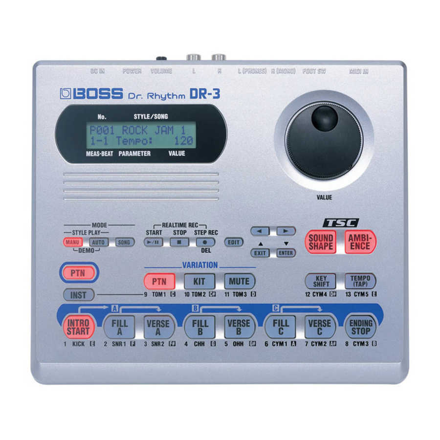
Page 3: Location Of Controls
DR-3 LOCATION OF CONTROLS fig.panel LOCATION OF CONTROLS PART LIST [Parts] Part Code Part Name Q’ty F2477101 DR-KNOB 02671212 ROTARY ENCODER EVE GB1F15 24B 03237812 RUBBER SW FOR DR-3 01566445 DIN CONNECTER YKF51-5067 (take off the shield plate) 02897334 6.5M JACK HTJ-064-10D 00569278 6.5M JACK LGR4609-7100 00451434... -
Page 4: Exploded View
Feb.2003 EXPLODED VIEW fig.bunkai EXPLODED VIEW PART LIST Part Code Part Name Q’ty F2477101 DR-KNOB 03237812 RUBBER SW G2027602 BATTERY COVER G2017617 BATTERY CASE G2177304 BATTERY TERMINAL(+/-) G2177306 BATTERY TERMINAL(-) G2177305 BATTERY TERMINAL(+) 03237856 BATTERY WIRING 03237845 BOTTOM FOOT... -
Page 5: Parts List
DR-3 PART LIST fig.part1E CONSIDERATION ON PARTS ORDRING SAFETY PRECAUTIONS: When ordering any parts listed in the parts list, please specify the following items in the order sheet. The parts marked have PART NUMBER DESCRIPTION MODEL NUMBER safety-related characteristics. Use 22575241 Sharp Key C-20/50... -
Page 6: Test Mode
Feb.2003 TEST MODE 10. FOOT SW Check 11. PIEZO Check 12. SQUAEW Check Required equipment 13. SINE Check 14. MUTE Check AC Adaptor PSA Series 15. Ending the Test Mode Foot Switch x2 (such as an FS-5U) 16. Checks for Normal Operation Foot Switch Cable (Roland PCS-31) 17. - Page 7 DR-3 Press the [EXIT] button to end the SRAM Check. fig.test5-2 2.FLASH Check fig.test2-1 Press the [EXIT] button to end the BATTERY Check. 6.MIDI CHECK Press the [ENTER] button. If there is no problem, the display will indicate “OK.” fig.test6-1 fig.test2-2 Press the [ENTER] button.
- Page 8 Feb.2003 Press the [ENTER] button. Make sure that all dots on the LCD screen are black and that there are not Press and release the FS-5U (to which the red line of the PCS-31 is missing dots. connected). Press the [ENTER] button. Press the [EXIT] button to end the FOOT SW Check.
- Page 9 DR-3 fig.volume shown above. • The waveform height must be from 1.8 V to 2.4 V. Disconnect the plug from R (MONO). Insert a stereo plug into L (PHONE) and waveforms of the tip and the ring. fig.lineout-4 L(PHONE) TIP / RING Use an oscilloscope to observe the waveforms from OUTPUT L/R (PIN jack) on the DR-3.
-
Page 10: Test Mode Error Message
Feb.2003 fig.error-1 Press the [INTRO START] button and check the sound of pattern playback. Turn the volume knob and make sure that the volume level changes smoothly. • aaaaaaaa ---> This indicates the address where the error occurred. This is Press the [STOP] button to stop playback. -
Page 11: Restoring The Factory Settings
DR-3 RESTORING THE FACTORY SETTINGS To execute a factory reset, press the [ENTER] button. The factory reset is executed. This restores the settings of the DR-3 to their When the factory reset ends, the original screen reappears. factory defaults. All settings are returned to the default values in effect when the unit was shipped from the factory. -
Page 12: Inportant Cautions When Replacing The Piezo Pickup Or Battery Wiring
Feb.2003 fig.update-3 fig.piezo-1 Switch off the DR-3 unit. IMPORTANT CAUTIONS WHEN REPLACING THE PIEZO PICKUP OR BATTERY WIRING How to Affix the Battery Wiring How to Affix the Piezo Pickup Use filament tape to affix the wiring from the battery to the bottom cover. fig.piezo-2 Swab the location on the circuit board for affixing the piezo element (the silkscreened region) with alcohol.
Need help?
Do you have a question about the Dr. Rhythm DR-3 and is the answer not in the manual?
Questions and answers