Table of Contents
Advertisement
Quick Links
Advertisement
Table of Contents

Related Manuals for METREL EurotestXD MI 3155


Summary of Contents for METREL EurotestXD MI 3155
-
Page 1: Instruction Manual
EurotestXD MI 3155 Instruction manual Version 1.3.4, Code no. 20 752 716... - Page 2 The trade names Metrel , Smartec , Eurotest , Auto Sequence are trademarks registered in Europe and other countries. No part of this publication may be reproduced or utilized in any form or by any means without permission in writing from METREL.
- Page 3 i. About the instruction manual This Instruction manual contains detailed information on the EurotestXD, its key features, functionalities and use. It is intended for technically qualified personnel responsible for the product and its use. Please note that LCD screenshots in this document may differ from the actual instrument screens in details due to firmware variations and modifications.
-
Page 4: Table Of Contents
MI 3155 EurotestXD Table of Contents Table of Contents General description ......................8 Warnings and notes ....................8 1.1.1 Safety warnings ....................... 8 1.1.2 Markings on the instrument ..................9 1.1.3 Warnings related to safety of batteries ..............9 1.1.4 Warnings related to safety of measurement functions ..........9 1.1.5 Notes related to measurement functions ............... - Page 5 MI 3155 EurotestXD Table of Contents 4.8.2 Workspace Manager main menu ................48 4.8.3 Operations with Workspaces ................. 49 4.8.4 Operations with Exports ..................49 4.8.5 Adding a new Workspace ..................51 4.8.6 Opening a Workspace ................... 52 4.8.7 Deleting a Workspace / Export ................52 4.8.8 Importing a Workspace ..................
- Page 6 MI 3155 EurotestXD Table of Contents 7.19 Z auto - Auto test sequence for fast line and loop testing ........146 Earth – Earth resistance (3-wire test) ..............148 7.20 Earth 2 clamp – Contactless earthing resistance measurement (with two current 7.21 clamps) ........................
- Page 7 Structure objects ..................224 Appendix E Default list of Auto Sequences ..............227 Appendix F Programming of Auto Sequences on Metrel ES Manager......228 Auto Sequence Editor workspace ................. 228 Managing groups of Auto Sequences ..............229 Auto Sequence® Name, Description and Image editing .......... 232 Search within selected Auto Sequence®...
- Page 8 MI 3155 EurotestXD Table of Contents Creating / modifying an Auto Sequence® ..............235 Description of flow commands ................. 236 Custom Inspections programming ................238 F.8.1 Creating and editing Custom Inspections ............238 F.8.2 Applying Custom Inspections................240...
-
Page 9: General Description
MI 3155 EurotestXD General description 1 General description Warnings and notes Read before use 1.1.1 Safety warnings In order to reach high level of operator safety while carrying out various measurements using the EurotestXD instrument, as well as to keep the test equipment undamaged, it is necessary to consider the following general warnings: ... -
Page 10: Markings On The Instrument
MI 3155 EurotestXD General description The instrument comes supplied with rechargeable Li-Ion battery pack. The battery pack should only be replaced with the same type as defined on the battery compartment label or as described in this manual! Hazardous voltages exist inside the instrument. -
Page 11: Notes Related To Measurement Functions
MI 3155 EurotestXD General description 1.1.5 Notes related to measurement functions Insulation resistance (R iso, R iso – all) The measuring range is decreased if using Tip commander A 1401. If a voltage of higher than 30 V (AC or DC) is detected between test terminals, the measurement will not be performed. - Page 12 MI 3155 EurotestXD General description Z loop, Zloop 4W, Zs rcd The specified accuracy of tested parameters is valid only if the mains voltage is stable during the measurement. The measurement accuracy and immunity against noise are higher if I test parameter in Zsrcd is set to ‘Standard’.
- Page 13 METREL assumes no responsibility for any Auto Sequence® by any means. It is the user’s responsibility, to check adequacy for the purpose of use of the selected Auto Sequence®.
-
Page 14: Testing Potential On Pe Terminal
MI 3155 EurotestXD General description Testing potential on PE terminal In certain instances faults on the installation's PE wire or any other accessible metal bonding parts can become exposed to live voltage. This is a very dangerous situation since the parts connected to the earthing system are considered to be free of potential. - Page 15 MI 3155 EurotestXD General description Test procedure Connect test cable to the instrument. Connect test leads to the object under test, see Figure 1.1 and Figure 1.2. Touch test probe for at least 1 second. If PE terminal is connected to phase voltage the warning message is displayed, display is yellow coloured, instrument buzzer is activated and further measurements are disabled: RCD tests, Z loop, Zs rcd, Z auto, AUTO TT, AUTO TN, AUTO TN (rcd) and Auto Sequences®.
-
Page 16: Battery And Charging Of Li-Ion Battery Pack
MI 3155 EurotestXD General description Battery and charging of Li-ion battery pack The instrument is designed to be powered by rechargeable Li-ion battery pack. The LCD contains an indication of battery condition (upper right section of LCD). In case the battery is too weak the instrument indicates this as shown in Figure 1.3. -
Page 17: Precharge
MI 3155 EurotestXD General description Typical charging profile which is also used in this instrument is shown in Figure 1.6. Current Regulation LOWV CH/8 Precharge Fastcharge Safety Time Time Figure 1.6: Typical charging profile where: ........Battery charging voltage ........Precharge threshold voltage LOWV ........ - Page 18 MI 3155 EurotestXD General description Typical charging time is 3 hours (Battery type: 18650T22A2S2P) in the temperature range of 5°C to 60°C. Charge Charge Charge Suspended Suspended ch/8 Temperature Figure 1.9: Typical charging current vs temperature profile where: ... Cold temperature threshold (typ. -15°C) ..
-
Page 19: Li - Ion Battery Pack Guidelines
MI 3155 EurotestXD General description Li – ion battery pack guidelines 1.3.2 Li – ion rechargeable battery pack requires routine maintenance and care in their use and handling. Read and follow the guidelines in this Instruction manual to safely use Li – ion battery pack and achieve the maximum battery life cycles. -
Page 20: Standards Applied
MI 3155 EurotestXD General description Standards applied The EurotestXD instruments are manufactured and tested in accordance with the following regulations: Electromagnetic compatibility (EMC) EN 61326-1 Electrical equipment for measurement, control and laboratory use – EMC requirements Class B (Hand-held equipment used in controlled EM environments) Safety (LVD) EN 61010-1 Safety requirements for electrical equipment for measurement, control and... -
Page 21: Instrument Set And Accessories
Li-ion battery pack, 7.2 V , 4400 mAh (Type: 18650T22A2S2P) Power supply adapter 12 V, 3 A (Type: CGSW-1203000) CD includes: PC software Metrel ES Manager Instruction manual “Guide for testing and verification of low voltage installations” handbook ... -
Page 22: Instrument Description
MI 3155 EurotestXD Instrument description 3 Instrument description Front panel Figure 3.1: Front panel 4,3“ COLOR TFT DISPLAY WITH TOUCH SCREEN SAVE key Stores actual measurement result(s) CURSOR keys Navigate in menus RUN key Start / stop selected measurement. Enter selected menu or option. View available values for selected parameter / limit. -
Page 23: Connector Panel
MI 3155 EurotestXD Instrument description Connector panel Figure 3.2: Connector panel Test connector L/L1 pin – In 4-wire measurements used as a current probe C1. N/L2 pin – In 4-wire measurements used as a current probe C2. PE/L3 pin – In 4-wire measurements used as a voltage probe P2. S pin –... -
Page 24: Back Side
MI 3155 EurotestXD Instrument description Back side Figure 3.3: Back view Battery / fuse compartment cover Fixing screws for battery / fuse compartment cover Back panel information label Figure 3.4: Battery and fuse compartment Type: 18650T22A2S2P 1 Li-ion battery pack Type: 18650T22A2S4P (optional) 2 Fuse F1 M 315 mA / 250 V... - Page 25 MI 3155 EurotestXD Instrument description 4 SD card slot Figure 3.5: Bottom view Neck belt openings Stand for desktop use Bottom information label Serial number label...
-
Page 26: Carrying The Instrument
MI 3155 EurotestXD Instrument description Carrying the instrument With the neck-carrying belt supplied in standard set, various possibilities of carrying the instrument are available. Operator can choose appropriate one on basis of his operation, see the following examples: The instrument hangs around operator’s neck only –... - Page 27 MI 3155 EurotestXD Instrument description Figure 3.7: Alternative method Please perform a periodical check of the attachment.
-
Page 28: Instrument Operation
MI 3155 EurotestXD Instrument operation 4 Instrument operation The EurotestXD instrument can be manipulated via a keypad or touch screen. General meaning of keys Cursor keys are used to: select appropriate option. Run key is used to: confirm selected option; ... -
Page 29: General Meaning Of Touch Gestures
MI 3155 EurotestXD Instrument operation General meaning of touch gestures Tap (briefly touch surface with fingertip) is used to: select appropriate option; confirm selected option; start and stop measurements. Swipe (press, move, lift) up / down is used to: ... -
Page 30: Virtual Keyboard
MI 3155 EurotestXD Instrument operation Virtual keyboard Figure 4.1: Virtual keyboard Toggle case between lowercase and uppercase. Active only when alphabetic characters keyboard layout selected. Backspace Clears last character or all characters if selected. (If held for 2 s, all characters are selected). Enter confirms new text. -
Page 31: Display And Sound
MI 3155 EurotestXD Instrument operation Display and sound 4.4.1 Terminal voltage monitor The terminal voltage monitor displays on-line the voltages on the test terminals and information about active test terminals in the a.c. installation measuring mode. Online voltages are displayed together with test terminal indication. All three test terminals are used for selected measurement. -
Page 32: Battery Indication
MI 3155 EurotestXD Instrument operation 4.4.2 Battery indication The battery indication indicates the charge condition of battery and connection of external charger. Battery capacity indication. Battery is in good condition. Battery is full. Low battery. Battery is too weak to guarantee correct result. Replace or recharge the battery cells. - Page 33 MI 3155 EurotestXD Instrument operation Instrument is overheated. The measurement is prohibited until the temperature decreases under the allowed limit. High electrical noise was detected during measurement. Results may be impaired. Indication of noise voltage above 5 V between H and E terminals during earth resistance measurement.
-
Page 34: Result Indication
MI 3155 EurotestXD Instrument operation 4.4.4 Result indication Measurement result is inside pre-set limits (PASS). Measurement result is out of pre-set limits (FAIL). Measurement is aborted. Consider displayed warnings and messages. RCD t and RCD I measurements will only be performed if the contact voltage in the pre-test at nominal differential current is lower than the set contact voltage limit! 4.4.5... -
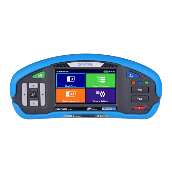
Page 35: Instruments Main Menu
MI 3155 EurotestXD Instrument operation Instruments main menu From the Main menu different main operation menus can be selected. Figure 4.2: Main menu Options Single Tests Menu with single tests, see chapter 6 Single tests. Auto Sequences Menu with customized test sequences, see chapter 8 Auto Sequences®. -
Page 36: General Settings
MI 3155 EurotestXD Instrument operation General Settings In the General settings menu general parameters and settings of the instrument can be viewed or set. Figure 4.3: General settings menu Options Language Instrument language selection. Power Save Brightness of LCD, enabling/disabling Bluetooth communication. Date /Time Instruments Date and time. -
Page 37: Language
MI 3155 EurotestXD Instrument operation Initial Settings Factory settings. About Instrument info. 4.6.1 Language In this menu the language of the instrument can be set. Figure 4.4: Language menu 4.6.2 Power Save In this menu different options for decreasing power consumption can be set. Figure 4.5: Power save menu Brightness Setting level of LCD brightness level. -
Page 38: Date And Time
MI 3155 EurotestXD Instrument operation 4.6.3 Date and time In this menu date and time of the instrument can be set. Figure 4.6: Setting date and time Note: If the batteries are removed the set date and time will be lost. 4.6.4 Workspace manager Refer to chapter 4.8 Workspace Manager for more information. -
Page 39: User Accounts
MI 3155 EurotestXD Instrument operation 4.6.6 User accounts The demand to sign in can prevent from unauthorized persons to work with the instrument. In this menu user accounts can be managed: Setting if signing in to work with the instrument is required or not. ... - Page 40 MI 3155 EurotestXD Instrument operation Sign in with selected user name. Enter the password and confirm. The user password consists of an up to 4 digit number. Administrator signing in The Account manager menu is accessed by selecting Account manager in Sign in menu or User profile menu. The account manager password must be entered and confirmed first.
- Page 41 MI 3155 EurotestXD Instrument operation The user can change its password. The actual password must be entered first followed by the new password. Enters the Account manager menu. 4.6.6.3 Managing accounts Figure 4.9: Account manager menu Options The Account manager menu is accessed by selecting Account manager in Sign in menu or User profile menu.
- Page 42 MI 3155 EurotestXD Instrument operation Enters procedure for changing the account manager (administrator) password. To change the password the actual and then the new password should be entered and confirmed. Enters menu for editing user accounts. Figure 4.10: Edit accounts menu Options Opens the window for adding a new user.
-
Page 43: Profiles
MI 3155 EurotestXD Instrument operation 4.6.7 Profiles Refer to chapter 4.7 Instrument profiles for more information. 4.6.8 Settings In this menu different general parameters can be set. Figure 4.11: Settings menu Available selection Description Touch screen [ON, OFF] Enables / disables operation with touch screen. - Page 44 MI 3155 EurotestXD Instrument operation The ‘None’ option is intended to disable the External Device [None, Commander] commander’s remote keys. In case of high EM interfering noise the operation of the commander can be irregular. Ignore PE [yes, no] [yes]: In IT earthing system the instrument will probe warning allow to start the selected measurement (IT)
-
Page 45: Devices
MI 3155 EurotestXD Instrument operation ½I 2I 5I N N N N RCD type I Note (mA) N 10 40 ms 40 ms 40 ms > 10 30 > 999 ms 300 ms 150 ms 40 ms Maximum break time >... -
Page 46: Initial Settings
MI 3155 EurotestXD Instrument operation Reading devices Type Sets appropriate reading device (QR or barcode scanner, RFID reader, via aMESM application). Port Sets communication port of selected reading device. Bluetooth device Goes to menu for pairing with selected Bluetooth device. name 4.6.10 Initial Settings In this menu the instrument settings, measurement parameters and limits can be set to initial... -
Page 47: About
MI 3155 EurotestXD Instrument operation 4.6.11 About In this menu instrument data (name, serial number, firmware (FW) and hardware (HW) version, fuse version and date of calibration) can be viewed. Figure 4.14: Instrument info screen... -
Page 48: Instrument Profiles
MI 3155 EurotestXD Instrument operation Instrument profiles In this menu the instrument profile can be selected from the available ones. Figure 4.15: Instrument profiles menu The instrument uses different specific system and measuring settings in regard to the scope of work or country it is used. -
Page 49: Workspace Manager
Workspaces are stored on SD card on directory WORKSPACES, while Exports are stored on directory EXPORTS. Export files can be read by METREL applications that run on other devices. Exports are suitable for making backups of important works. To work on the instrument an Export should be imported first from the list of Exports and converted to a Workspace. -
Page 50: Operations With Workspaces
MI 3155 EurotestXD Instrument operation 4.8.3 Operations with Workspaces Only one Workspace can be opened in the instrument at the same time. The Workspace selected in the Workspace Manager will be opened in the Memory Organizer. Figure 4.17: Workspaces menu Options Marks the opened Workspace in Memory Organizer. - Page 51 MI 3155 EurotestXD Instrument operation Options Deletes the selected Export. Refer to chapter 4.8.7 Deleting a Workspace / Export for more information. Imports a new Workspace from Export. Refer to 4.8.8 Importing a Workspace for more information. Opens more options in control panel / expands column.
-
Page 52: Adding A New Workspace
MI 3155 EurotestXD Instrument operation 4.8.5 Adding a new Workspace Procedure New Workspaces can be added from the Workspace Manager screen. Enters option for adding a new Workspace. Keypad for entering name of a new Workspace is displayed after selecting New. -
Page 53: Opening A Workspace
MI 3155 EurotestXD Instrument operation 4.8.6 Opening a Workspace Procedure Workspace can be selected from a list in Workspace manager screen. Opens a Workspace in Workspace manager. The opened Workspace is marked with a blue dot. The previously opened Workspace will close automatically. -
Page 54: Importing A Workspace
MI 3155 EurotestXD Instrument operation Workspace / Export is deleted from the Workspace / Export list. 4.8.8 Importing a Workspace Select an Export file to be imported from Workspace manager Export list. Enters option Import. Before the import of the selected Export file the user is asked for confirmation. -
Page 55: Exporting A Workspace
MI 3155 EurotestXD Instrument operation 4.8.9 Exporting a Workspace Select a Workspace from Workspace manager list to be exported to an Export file. Enters option Export. Before exporting the selected Workspace the user is asked for confirmation. Workspace is exported to Export file and is added to the list of Exports. -
Page 56: Auto Sequence® Groups
MI 3155 EurotestXD Instrument operation Auto Sequence® groups The Auto Sequences® in MI 3155 EurotestXD can be organized by using lists. In a list a group of similar Auto Sequences® is stored. The Auto Sequence® groups menu is intended to manage with different lists of Auto Sequences®... - Page 57 MI 3155 EurotestXD Instrument operation 4.9.1.1 Selecting a list of Auto Sequences Procedure A list of Auto Sequences can be selected from the Auto Sequence groups menu. Enters option for selecting a list. Selected list of Auto Sequences is marked with a blue dot.
-
Page 58: Memory Organizer
MI 3155 EurotestXD Memory Organizer 5 Memory Organizer Memory Organizer is a tool for storing and working with test data. Memory Organizer menu The data is organized in a tree structure with Structure objects and Measurements. MI 3155 – EurotestXD Instrument has a multi-level structure. The hierarchy of Structure objects in the tree is shown on Figure 5.1. -
Page 59: Structure Objects
MI 3155 EurotestXD Memory Organizer Statuses of Single tests passed finished single test with test results failed finished single test with test results finished single test with test results and no status empty single test without test results Overall statuses of Auto Sequence® At least one single test in the Auto sequence... - Page 60 MI 3155 EurotestXD Memory Organizer Options There are no measurement results under selected structure object. Measurements should be made. One or more measurement result(s) under selected structure object has failed. Not all measurements under selected structure object have been made yet. All measurements under selected structure object are completed but one or more...
-
Page 61: Selecting An Active Workspace In Memory Organizer
MI 3155 EurotestXD Memory Organizer 5.1.3 Selecting an active Workspace in Memory Organizer Memory Organizer and Workspace Manager are interconnected so an active Workspace can be selected also in the Memory Organizer menu. Procedure Press the active Workspace in Memory ... -
Page 62: Adding Nodes In Memory Organizer
MI 3155 EurotestXD Memory Organizer 5.1.4 Adding Nodes in Memory Organizer Structural Elements (Nodes) are used to ease organization of data in the Memory Organizer. One Node is a must; others are optional and can be created or deleted freely. Procedure Press the active Workspace in Memory ... -
Page 63: Operations In Tree Menu
MI 3155 EurotestXD Memory Organizer 5.1.5 Operations in Tree menu In the Memory organizer different actions can be taken with help of the control panel at the right side of the display. Possible actions depend on the selected element in the organizer. 5.1.5.1 Operations on measurements (finished or empty measurements) Figure 5.4: A measurement is selected in the Tree menu... - Page 64 MI 3155 EurotestXD Memory Organizer Deletes a measurement. Selected Measurement can be deleted. User is asked for confirmation before the deleting. Refer to chapter 5.1.5.12 Delete a measurement for more information. 5.1.5.2 Operations on Structure objects The structure object must be selected first. Figure 5.5: A structure object is selected in the Tree menu Options Starts a new measurement.
- Page 65 MI 3155 EurotestXD Memory Organizer Copies & Paste a Structure object. Selected Structure object can be copied and pasted to any allowed location in structure tree. Multiple “Paste” is allowed. Refer to chapter 5.1.5.8 Copy & Paste a Structure object for more information. Views and edit comments.
- Page 66 MI 3155 EurotestXD Memory Organizer 5.1.5.3 View / Edit parameters and attachments of a Structure object The parameters and their content are displayed in this menu. To edit the selected parameter, tap on it or press the key to enter menu for editing parameters. Procedure ...
- Page 67 MI 3155 EurotestXD Memory Organizer Attachments The name of attachment can be seen. Operation with attachments is not supported in the instrument. Select Comments in Control panel. View or edit comments Complete comment (if exists) attached to the structure object can be seen on this screen.
- Page 68 MI 3155 EurotestXD Memory Organizer 5.1.5.4 Add a new Structure Object This menu is intended to add new structure objects in the tree menu. A new structure object can be selected and then added in the tree menu. Procedure Default initial structure.
- Page 69 MI 3155 EurotestXD Memory Organizer Parameters of the Structure object can be edited. Adds the selected structure object in the tree menu. Returns to the tree menu without changes. New object added.
- Page 70 MI 3155 EurotestXD Memory Organizer 5.1.5.5 Add a new measurement In this menu new empty measurements can be set and then added in the structure tree. The type of measurement, measurement function and its parameters are first selected and then added under the selected Structure object.
- Page 71 MI 3155 EurotestXD Memory Organizer Select parameter and modify it as described earlier. Refer to chapter 6.1.2 Setting parameters and limits of single tests for more information. Adds the measurement under the selected Structure object in the tree menu. Returns to the structure tree menu without changes.
- Page 72 MI 3155 EurotestXD Memory Organizer 5.1.5.6 Clone a Structure object In this menu selected structure object can be copied (cloned) to same level in the structure tree. Cloned structure object has the same name as the original. Procedure Select the structure object to be cloned. ...
- Page 73 MI 3155 EurotestXD Memory Organizer 5.1.5.7 Clone a measurement By using this function a selected empty or finished measurement can be copied (cloned) as an empty measurement to the same level in the structure tree. Parameters and limits of new measurement are the same as they are set in original measurement.
- Page 74 MI 3155 EurotestXD Memory Organizer 5.1.5.8 Copy & Paste a Structure object In this menu selected Structure object can be copied and pasted to any allowed location in the structure tree. Procedure Select the structure object to be copied. ...
- Page 75 MI 3155 EurotestXD Memory Organizer The new structure object is displayed. Note The Paste command can be executed one or more times. 5.1.5.9 Cloning and Pasting sub-elements of selected structure object When structure object is selected to be cloned, or copied & pasted, additional selection of its sub-elements is needed.
- Page 76 MI 3155 EurotestXD Memory Organizer 5.1.5.10 Copy & Paste a measurement In this menu selected measurement can be copied as an empty measurement to any allowed location in the structure tree. Selected measurement can be copied multiple times to different locations in the structure tree.
- Page 77 MI 3155 EurotestXD Memory Organizer 5.1.5.11 Delete a Structure object In this menu selected Structure object can be deleted. Procedure Select the structure object to be deleted. Select Delete in Control panel. A confirmation window will appear. Selected structure object and its sub- elements are removed.
- Page 78 MI 3155 EurotestXD Memory Organizer 5.1.5.12 Delete a measurement In this menu selected measurement can be deleted from selected location in the tree structure. Procedure Select a measurement to be deleted. Select Delete in Control panel. A confirmation window will appear. Selected measurement is deleted.
- Page 79 MI 3155 EurotestXD Memory Organizer 5.1.5.13 Rename a Structure object In this menu selected Structure object can be renamed. Procedure Select the structure object to be renamed. Select Rename in Control panel. Virtual keypad will appear on screen. Enter new text and confirm.
- Page 80 MI 3155 EurotestXD Memory Organizer 5.1.5.14 Recall and Retest selected measurement Procedure Select the measurement to be recalled. Select Recall results in Control panel. Measurement is recalled. Parameters and limits can be viewed but cannot be edited. ...
-
Page 81: Searching In Memory Organizer
MI 3155 EurotestXD Memory Organizer Parameters and limits can be viewed and edited. Select Run in Control panel to retest the measurement. Results / sub-results after re-run of recalled measurement. Select Save results in Control panel. Retested measurement is saved under same structure object as original one. - Page 82 MI 3155 EurotestXD Memory Organizer Procedure Search function is available from the active workspace directory line. Select Search in control panel to open Search setup menu. The parameter that can be searched for is displayed in the search setup menu. Name is referred to all structure objects.
- Page 83 MI 3155 EurotestXD Memory Organizer Searches through the Memory Organizer for objects according to the set filter. The results are shown in the Search results screen presented on Figure 5.7. Figure 5.7: Search results screen (left), structure object selected (right) Options Next page (if available).
-
Page 84: Single Tests
MI 3155 EurotestXD Single tests 6 Single tests Single tests can be selected in the main Single tests menu or in Memory organizer main menu and sub-menus. Selection modes In Single test main menu four modes for selecting single tests are available. Options Area Group With help of area groups it is possible to limit... -
Page 85: Single Test (Measurement) Screens
MI 3155 EurotestXD Single tests Cross selector This selection mode is the fastest for working with the keypad. Groups of single tests are organized in a row. For the selected group all single tests are displayed and easy accessible with up /down keys. - Page 86 MI 3155 EurotestXD Single tests function name battery status real time clock Control panel (available options) Parameters (white) and limits (red) Result field: main result(s) sub-result(s) PASS / FAIL indication Voltage monitor with info and warning symbols...
-
Page 87: Setting Parameters And Limits Of Single Tests
MI 3155 EurotestXD Single tests 6.1.2 Setting parameters and limits of single tests Procedure Select the test or measurement. The test can be entered from: Single tests menu or Memory organizer menu once the empty measurement was created in selected object structure. -
Page 88: Single Test Start Screen
MI 3155 EurotestXD Single tests Accepts the new parameters and limit values and exits. 6.1.3 Single test start screen Figure 6.2: Single test start screen, example of insulation resistance measurement Options (before test, screen was opened in Memory organizer or Single test main menu): Starts the measurement. -
Page 89: Single Test Screen During Test
MI 3155 EurotestXD Single tests 6.1.4 Single test screen during test Figure 6.3: Single test is running, example of insulation resistance continuous measurement Operations when test is running: Stops the single test measurement. Proceeds to next step of the measurement (if measurement consists of more steps). -
Page 90: Single Test Result Screen
MI 3155 EurotestXD Single tests 6.1.5 Single test result screen Figure 6.4: Single test results screen, example of insulation resistance measurement results Options (after measurement is finished) Starts a new measurement. Starts a new continuous measurement (if applicable long on selected single test). long Saves the result. - Page 91 MI 3155 EurotestXD Single tests a new measurement will be saved under the selected Structure object. Opens screen for changing parameters and limits. Refer to chapter 6.1.2 Setting parameters and limits of single tests for more information. Adds comment to the measurement. The instrument opens keypad for entering a comment.
-
Page 92: Editing Graphs (Harmonics)
MI 3155 EurotestXD Single tests 6.1.6 Editing graphs (Harmonics) Figure 6.5: Example of Harmonics measurement results Options for editing graphs (start screen or after measurement is finished) Plot edit Opens control panel for editing graphs. Increase scale factor for y-axis. Decrease scale factor for y-axis. -
Page 93: Single Test (Inspection) Screens
MI 3155 EurotestXD Single tests 6.1.7 Single test (inspection) screens Visual and Functional inspections can be treated as a special class of tests. Items to be visually or functionally checked are displayed. In addition on-line statuses and other information are displayed. - Page 94 MI 3155 EurotestXD Single tests Starts the inspection. Opens help screens. Refer to chapter 6.1.8 Help screens for more information. 6.1.7.2 Single test (Inspection) screen during test Figure 6.8: Inspection screen (during inspection) Options (during test) Selects item. Stops the inspection. Applies a pass to the selected item or group of items.
- Page 95 MI 3155 EurotestXD Single tests Rules for automatic applying of statuses: The parent item(s) can automatically get a status on base of statuses in child items. the fail status has highest priority. A fail status for any item will result in a fail status in all ...
- Page 96 MI 3155 EurotestXD Single tests A new measurement will be saved under the selected Structure object. Adds comment to the measurement. The instrument opens keypad for entering a comment. Opens help screens. Refer to chapter 6.1.8 Help screens for more information. 6.1.7.4 Single test (inspection) memory screen Figure 6.10: Inspection memory screen...
-
Page 97: Help Screens
MI 3155 EurotestXD Single tests 6.1.8 Help screens Help screens contain diagrams for proper connection of the instrument. Figure 6.11: Examples of help screens Options Opens help screen. Goes to previous / next help screen. Back to test / measurement menu. -
Page 98: Recall Single Test Results Screen
MI 3155 EurotestXD Single tests 6.1.9 Recall single test results screen Figure 6.12: Recalled results of selected measurement, example of insulation resistance recalled results Options Retest Enters starting screen for a new measurement. Refer to chapter 6.1.3 Single test start screen for more information. -
Page 99: Tests And Measurements
MI 3155 EurotestXD Tests and measurements 7 Tests and measurements See chapter 6.1 Selection modes for instructions on keys and touch screen functionality. Voltage, frequency and phase sequence Figure 7.1: Voltage measurement menu Measurement parameters System Voltage system [-, 1-phase,3-phase] Limit type Type of limit [Voltage, %] Earthing system... - Page 100 MI 3155 EurotestXD Test and measurements Measurement limits for IT earthing system: 7,9) Min. voltage [0 V … 499 V] Low limit U12 7,9) Max. voltage [0 V … 499 V] High limit U12 Min. voltage [-20% … 20%] Low limit U12 Max.
- Page 101 MI 3155 EurotestXD Test and measurements Measurement procedure Enter the Voltage function. Set test parameters / limits. Connect test cable to the instrument. Connect test leads to object under test (see Figure 7.2 and Figure 7.3). ...
- Page 102 MI 3155 EurotestXD Test and measurements Three-phase TN/TT and IT system: voltage between phases L1 and L2 voltage between phases L1 and L3 voltage between phases L2 and L3 Freq frequency 1.2.3 - correct connection – CW rotation sequence Field 3.2.1 - invalid connection –...
-
Page 103: R Iso - Insulation Resistance
MI 3155 EurotestXD Test and measurements R iso – Insulation resistance Figure 7.6: Insulation resistance measurement menu Measurement parameters / limits Uiso Nominal test voltage [50 V, 100 V, 250 V, 500 V, 1000 V, 2500 V] Type of test [-, L/PE, L/N, N/PE, L/L, L1/L2, L1/L3, L2/L3, L1/N, L2/N, L3/N, Type Riso L1/PE, L2/PE, L3/PE] Limit(Riso) - Page 104 MI 3155 EurotestXD Test and measurements Connection diagrams ≤ 1 kV) Figure 7.7: Connections of 3-wire test lead and Tip commander (U Figure 7.8: Connection of 2.5 kV test lead (U =2.5 kV)
-
Page 105: R Iso All - Insulation Resistance
MI 3155 EurotestXD Test and measurements Measurement procedure Enter the R iso function. Set test parameters / limits. Disconnect tested installation from mains supply and discharge installation as required. Connect test cable to the instrument. Connect test leads to object under test (see Figure 7.7 and Figure 7.8). - Page 106 MI 3155 EurotestXD Test and measurements Connection diagrams Figure 7.11: Connection of 3-wire test lead and Tip commander Measurement procedure Enter the R iso - all function. Set test parameters / limits. Disconnect tested installation from mains supply and discharge installation as required. ...
-
Page 107: The Dar And Pi Diagnostic
������ ���� = �� ( 1 min ) ������ For additional information regarding PI and DAR diagnostic, please refer to Metrel’s handbook Modern insulation testing. Figure 7.13: Diagnostic test menu Measurement parameters / limits Uiso Nominal test voltage [500 V, 1000 V, 2500 V] Connection diagrams ≤... - Page 108 MI 3155 EurotestXD Test and measurements Figure 7.15: Connection of 2.5 kV test lead (U = 2.5 kV) Measurement procedure Enter the Diagnostic test function. Set test parameters / limits. Disconnect tested installation from mains supply and discharge installation as required. ...
-
Page 109: Varistor Test
MI 3155 EurotestXD Test and measurements Varistor test Measuring principle A voltage ramp starts from 50 V and rises with a slope of 100 V/s (Range parameter set to 1000 V) or 350 V/s (Range parameter set to 2500 V). The measurement ends when the defined end voltage is reached or if the test current exceeds the value of 1 mA. - Page 110 MI 3155 EurotestXD Test and measurements Figure 7.19: Connection of 2.5 kV test lead (Range: 2500 V) Measurement procedure Enter the Varistor test function. Set test parameters / limits. Connect test cable to the instrument. Connect test leads to object under test (see Figure 7.18 and Figure 7.19). Different test cable must be used if testing at Range: 1000 V or 2500 V.
-
Page 111: R Low - Resistance Of Earth Connection And Equipotential Bonding
MI 3155 EurotestXD Test and measurements ������ ������ ≈ 1.15 × √2 Uac voltage may be directly compared with the voltage declared on tested protection device. R low – Resistance of earth connection and equipotential bonding Figure 7.21: R low measurement menu Measurement parameters / limits Output [LPE, LN]... -
Page 112: R Low 4W
MI 3155 EurotestXD Test and measurements Connect 3-wire test lead to the instrument. Compensate the test leads resistance if necessary, see section 7.8.1 Compensation of test leads resistance. Disconnect tested installation from mains supply and discharge insulation as required. ... - Page 113 MI 3155 EurotestXD Test and measurements Connection diagram Figure 7.25: Connection of 4-wire test lead plus optional extension leads Measurement procedure Enter the R low 4W function. Set test parameters / limits. Connect 4-wire test lead to the instrument. ...
-
Page 114: Continuity - Continuous Resistance Measurement With Low Current
MI 3155 EurotestXD Test and measurements Continuity – Continuous resistance measurement with low current Figure 7.27: Continuity resistance measurement menu Measurement parameters / limits Sound [On*, Off] Max. resistance [Off, 0.1 Ω ... 20.0 Ω] Limit(R) *Instrument sounds if resistance is lower than the set limit value. Connection diagrams Figure 7.28: Tip commander and 3-wire test lead applications... -
Page 115: Compensation Of Test Leads Resistance
MI 3155 EurotestXD Test and measurements Measurement procedure Enter the Continuity function. Set test parameters / limits. Connect test cable to the instrument. Compensate the test leads resistance if necessary, see section 7.8.1 Compensation of test leads resistance. ... - Page 116 MI 3155 EurotestXD Test and measurements Compensation of test leads resistance procedure Enter R low or Continuity function. Connect test cable to the instrument and short all test leads together, see Figure 7.30. Touch the key to compensate leads resistance. Figure 7.31: Result with old and new calibration values...
-
Page 117: Testing Rcds
MI 3155 EurotestXD Test and measurements Testing RCDs Various test and measurements are required for verification of RCD(s) in RCD protected installations. Measurements are based on the EN 61557-6 standard. The following measurements and tests (sub-functions) can be performed: Contact voltage, ... -
Page 118: Rcd Uc - Contact Voltage
MI 3155 EurotestXD Test and measurements Parameter is available only when RCD I test is selected and parameter Use is set to ‘other’. Connection diagrams Figure 7.33: Connecting the Plug commander and the 3-wire test lead Figure 7.34: Connection for Uc(P) measurement RCD Uc –... - Page 119 MI 3155 EurotestXD Test and measurements Test procedure Enter the RCD Uc function. Set test parameters / limits. Connect test cables to the instrument. Connect L, N and PE of 3-wire test lead or Plug commander to the object under test, see Figure 7.33.
-
Page 120: Rcd T - Trip-Out Time
MI 3155 EurotestXD Test and measurements RCD t – Trip-out time 7.9.2 Test procedure Enter the RCD t function. Set test parameters / limits. Connect test cable to the instrument. Connect 3-wire test lead or Plug commander to the object under test, see Figure 7.33. - Page 121 MI 3155 EurotestXD Test and measurements Figure 7.37: Examples of Trip-out current measurement result Test results / sub-results Trip-out current I∆ Contact voltage Uc I∆ Contact voltage at trip-out current I∆ or no value if the RCD didn’t trip t I∆ Trip-out time at trip-out current I∆...
-
Page 122: Rcd Auto - Rcd Auto Test
MI 3155 EurotestXD Test and measurements RCD Auto – RCD Auto test 7.10 RCD Auto test function performs a complete RCD test (trip-out time at different residual currents, trip-out current and contact voltage) in one set of automatic tests, guided by the instrument. - Page 123 MI 3155 EurotestXD Test and measurements Step 3 Step 4 Step 5 Step 6 Step 7 Step 8 Figure 7.38: Individual steps in RCD Auto test...
- Page 124 MI 3155 EurotestXD Test and measurements Test results / sub-results t I∆N x1, (+) Step 1 trip-out time (I , (+) positive polarity) N t I∆N x1, (-) Step 2 trip-out time (I , (-) negative polarity) N t I∆N x5, (+) Step 3 trip-out time (I =5I...
-
Page 125: Z Loop - Fault Loop Impedance And Prospective Fault Current
MI 3155 EurotestXD Test and measurements Z loop – Fault loop impedance and prospective fault 7.11 current Figure 7.39: Z loop menu Measurement parameters / limits Fuse Type Selection of fuse type [Off, gG, NV, B, C, D, K, Custom] Fuse I Rated current of selected fuse Fuse t... - Page 126 MI 3155 EurotestXD Test and measurements Figure 7.41: Connection for Uc(P) measurement Measurement procedure Enter the Z loop function. Set test parameters / limits. Connect test cable to the instrument. Connect 3-wire test lead or Plug commander to the object under test, see Figure 7.40.
- Page 127 MI 3155 EurotestXD Test and measurements ..Correction factor (Isc factor) for I . Refer to chapter 4.6.8 Settings for more information. Uc(P) ..Voltage between external earthed point and main earthing point (P/S and PE terminals), see calculation below Input voltage range (L-PE) 110 V (93 V ...
-
Page 128: Z Loop 4W - Fault Loop Impedance And Prospective Fault Current
MI 3155 EurotestXD Test and measurements Z loop 4W – Fault loop impedance and prospective 7.12 fault current Figure 7.43: Z loop 4W menu Measurement parameters / limits Fuse Type Selection of fuse type [Off, gG, NV, B, C, D, K, Custom] Fuse I Rated current of selected fuse Fuse t... - Page 129 MI 3155 EurotestXD Test and measurements Figure 7.45: Example of Z loop 4W measurement result Measurement results / sub-results Loop impedance Ipsc Prospective fault current Ulpe Voltage L-PE Resistance of loop impedance Reactance of loop impedance Prospective fault current I is calculated from measured impedance as follows: ...
-
Page 130: Zs Rcd - Fault Loop Impedance And Prospective Fault Current In System With Rcd
MI 3155 EurotestXD Test and measurements Zs rcd – Fault loop impedance and prospective fault 7.13 current in system with RCD Zs rcd measurement prevents trip-out of the RCD in systems with the RCD. Figure 7.46: Zs rcd menu Measurement parameters / limits Protection Protection type [TN, TTrcd] Fuse Type... - Page 131 MI 3155 EurotestXD Test and measurements Connection diagrams Figure 7.47: Connection of Plug commander and 3-wire test lead Figure 7.48: Connection for Uc(P) measurement Measurement procedure Enter the Zs rcd function. Set test parameters / limits. Connect test cable to the instrument. ...
- Page 132 MI 3155 EurotestXD Test and measurements Measurement results / sub-results Loop impedance Ipsc Prospective fault current Ulpe Voltage L-PE Contact voltage at nominal residual current Uc (P) Contact voltage at prospective fault current (external probe) Contact voltage at nominal residual current (external probe) Resistance of loop impedance Reactance of loop impedance Result is presented only if Protection is set to TTrcd.
-
Page 133: Z Loop M - High Precision Fault Loop Impedance And Prospective Fault Current
MI 3155 EurotestXD Test and measurements Z loop m – High precision fault loop impedance 7.14 and prospective fault current Figure 7.50: Z loop mΩ menu Measurement parameters / limits Fuse Type Selection of fuse type [Off, gG, NV, B, C, D, K, Custom] Fuse I Rated current of selected fuse Fuse t... - Page 134 MI 3155 EurotestXD Test and measurements Figure 7.52: Contact voltage measurement – Connection of A 1143 Measurement procedure Enter the Z loop m function. Set test parameters / limits. Connect test leads to A 1143 – Euro Z 290 A adapter and switch it on. ...
- Page 135 MI 3155 EurotestXD Test and measurements Standard prospective fault current I is calculated as follows: 230 �� �� = 230 �� ± 10 % �� where ��−���� ������ �� The prospective fault currents I and I are calculated as follows: = √...
-
Page 136: Z Line - Line Impedance And Prospective Short-Circuit Current
MI 3155 EurotestXD Test and measurements Z line – Line impedance and prospective short- 7.15 circuit current Figure 7.54: Z line measurement menu Measurement parameters / limits Fuse Type Selection of fuse type [Off, gG, NV, B, C, D, K, Custom] Fuse I Rated current of selected fuse Fuse t... - Page 137 MI 3155 EurotestXD Test and measurements Measurement procedure Enter the Z line function. Set test parameters / limits. Connect test cable to the instrument. Connect 3-wire test lead or Plug commander to the object under test, see Figure 7.55.
- Page 138 MI 3155 EurotestXD Test and measurements The prospective short-circuit currents I and I are calculated as Min2p Min3p Max2p Max3p follows: �� = √ (1.5 × �� + �� �� �� ( ��−�� ) ℎ���� (��−��) (��−��) ������ ��(��−��) �� where ������...
-
Page 139: Z Line 4W - Line Impedance And Prospective Short-Circuit Current
MI 3155 EurotestXD Test and measurements Z line 4W – Line impedance and prospective short- 7.16 circuit current Figure 7.57: Z line 4 W measurement menu Measurement parameters / limits Fuse Type Selection of fuse type [Off, gG, NV, B, C, D, K, Custom] Fuse I Rated current of selected fuse Fuse t... - Page 140 MI 3155 EurotestXD Test and measurements Measurement procedure Enter the Z line 4W function. Set test parameters / limits. Connect test cable to the instrument. Connect 4-wire test lead to the object under test, see Figure 7.58. ...
-
Page 141: Z Line M - High Precision Line Impedance And Prospective Short-Circuit Current
MI 3155 EurotestXD Test and measurements Z line m – High precision line impedance and 7.17 prospective short-circuit current Figure 7.60: Z line mΩ menu Measurement parameters / limits Test Type of test [L/N, L/L] Fuse Type Selection of fuse type [Off, gG, NV, B, C, D, K, Custom] Fuse I Rated current of selected fuse Fuse t... - Page 142 MI 3155 EurotestXD Test and measurements Measurement procedure Enter the Z line m function. Set test parameters / limits. Connect test leads to A 1143 – Euro Z 290 A adapter and switch it on. Connect A 1143 – Euro Z 290 A adapter to the instrument using RS232-PS/2 cable. ...
- Page 143 MI 3155 EurotestXD Test and measurements The prospective short-circuit currents I and I are calculated as Min2p Min3p Max2p Max3p follows: �� = √ (1.5 × �� + �� �� �� ( ��−�� ) ℎ���� (��−��) (��−��) ������ ��(��−��) �� where ������...
-
Page 144: Voltage Drop
MI 3155 EurotestXD Test and measurements Voltage Drop 7.18 The voltage drop is calculated based on the difference of line impedance at connection points (sockets) and the line impedance at the reference point (usually the impedance at the switchboard). Figure 7.63: Voltage drop menu Measurement parameters / limits Fuse Type Selection of fuse type [Off, gG, NV, B, C, D, K, Custom]... - Page 145 MI 3155 EurotestXD Test and measurements Measurement procedure STEP 1: Measuring the impedance Zref at origin Enter the Voltage Drop function. Set test parameters / limits. Connect test cable to the instrument. Connect 3-wire test lead to the origin of electrical installation, see Figure 7.64.
- Page 146 MI 3155 EurotestXD Test and measurements Measurement results / sub-results U Voltage drop Ipsc Prospective short-circuit current Voltage L-N Zref Reference line impedance Line impedance Voltage drop is calculated as follows: where: ΔU Calculated Voltage drop Zref Impedance at reference point (at origin)
-
Page 147: Z Auto - Auto Test Sequence For Fast Line And Loop Testing
MI 3155 EurotestXD Test and measurements Z auto - Auto test sequence for fast line and loop 7.19 testing Tests / measurements implemented in Z auto test sequence Voltage Z line Voltage Drop Zs rcd Figure 7.67: Z auto menu Measurement parameters / limits Protection Protection type [TN, TNrcd, TTrcd]... - Page 148 MI 3155 EurotestXD Test and measurements Connection diagram Figure 7.68: Z auto measurement Measurement procedure Enter the Z auto function. Set test parameters / limits. Measure the impedance Zref at origin (optional), see chapter 7.18 Voltage Drop. ...
-
Page 149: Earth - Earth Resistance (3-Wire Test)
MI 3155 EurotestXD Test and measurements Earth – Earth resistance (3-wire test) 7.20 Figure 7.70: Earth menu Measurement parameters / limits Maximum resistance [Off, 1 ... 5 k] Limit(Re) Connection diagrams Figure 7.71: Resistance to earth, measurement of main installation earthing Figure 7.72: Resistance to earth, measurement of a lighting protection system... - Page 150 MI 3155 EurotestXD Test and measurements Measurement procedure Enter the Earth function. Set test parameters / limits. Connect test cable to the instrument. Connect 3-wire test lead to the object under test, see Figure 7.71 and Figure 7.72.
-
Page 151: Earth 2 Clamp - Contactless Earthing Resistance Measurement (With Two Current Clamps)
MI 3155 EurotestXD Test and measurements Earth 2 clamp – Contactless earthing resistance 7.21 measurement (with two current clamps) Figure 7.74: Earth 2 clamps menu Measurement parameters / limits Maximum resistance [Off, 1 ... 30 ] Limit(Re) Connection diagram Figure 7.75: Contactless earthing resistance measurement Measurement procedure ... -
Page 152: Ro - Specific Earth Resistance
MI 3155 EurotestXD Test and measurements Figure 7.76: Examples of Contactless earthing resistance measurement result Measurement results / sub-results Earth resistance Ro – Specific earth resistance 7.22 Figure 7.77: Earth Ro menu Measurement parameters / limits Length Unit Length unit [m, ft] Distance Distance between probes [0.1 m ... - Page 153 MI 3155 EurotestXD Test and measurements Measurement procedure Enter the Ro function. Set test parameters / limits. Connect A 1199 adapter to the instrument. Connect test leads to earth probes, see Figure 7.78. Start the measurement. ...
-
Page 154: Power
MI 3155 EurotestXD Test and measurements Power 7.23 Figure 7.80: Power menu Measurement parameters / limits Ch1 clamp type Current clamp adapter [A1018, A1019, A1391] Range Range for selected current clamp adapter A1018 [20 A] A1019 [20 A] A1391 [40 A, 300 A] Connection diagram Figure 7.81: Power measurement Measurement procedure... - Page 155 MI 3155 EurotestXD Test and measurements Figure 7.82: Example of Power measurement result Measurement results / sub-results Active power Apparent power Reactive power (capacitive or inductive) Power factor (capacitive or inductive) THDu Voltage total harmonic distortion...
-
Page 156: Harmonics
MI 3155 EurotestXD Test and measurements Harmonics 7.24 Figure 7.83: Harmonics menu Measurement parameters / limits Ch1 clamp type Current clamp adapter [A1018, A1019, A1391] Range Range for selected current clamp adapter A1018 [20 A] A1019 [20 A] A1391 [40 A, 300 A] Limit(THDu) Max. - Page 157 MI 3155 EurotestXD Test and measurements Figure 7.85: Examples of Harmonics measurement results Measurement results / sub-results U:h(i) TRMS voltage of selected harmonic [h0 ... h11] I:h(i) TRMS current of selected harmonic [h0 ... h11] THDu Voltage total harmonic distortion THDi Current total harmonic distortion...
-
Page 158: Currents
MI 3155 EurotestXD Test and measurements Currents 7.25 Figure 7.86: Current menu Measurement parameters / limits Ch1 clamp type Current clamp adapter [A1018, A1019, A1391] Range Range for selected current clamp adapter A1018 [20 A] A1019 [20 A] A1391 [40 A, 300 A] Limit(I1) Max. - Page 159 MI 3155 EurotestXD Test and measurements Figure 7.88: Examples of Current measurement result Measurement results / sub-results PE leakage or load current...
-
Page 160: Isfl - First Fault Leakage Current
MI 3155 EurotestXD Test and measurements ISFL – First fault leakage current 7.26 Figure 7.89: ISFL measurement menu Measurement parameters / limits Imax(Isc1, Isc2) Maximum first fault leakage current [Off, 3.0 mA ... 19.5 mA] Connection diagrams Figure 7.90: Measurement of highest First fault leakage current with 3-wire test lead Figure 7.91: Measurement of First fault leakage current for RCD protected circuit with 3- wire test lead... - Page 161 MI 3155 EurotestXD Test and measurements Measurement procedure Enter the ISFL function. Set test parameters / limits. Connect test cable to the instrument. Connect 3-wire test lead to the object under test, see Figure 7.90 and Figure 7.91.
-
Page 162: Imd - Testing Of Insulation Monitoring Devices
MI 3155 EurotestXD Test and measurements IMD – Testing of insulation monitoring devices 7.27 This function checks the alarm threshold of insulation monitor devices (IMD) by applying a changeable resistance between L1/PE and L2/PE terminals. Figure 7.93: IMD test menu Test parameters / limits Test Test mode [MANUAL R, MANUAL I, AUTO R, AUTO I]... - Page 163 MI 3155 EurotestXD Test and measurements Test procedure (MANUAL R, MANUAL I) Enter the IMD function. Set test parameter to MANUAL R or MANUAL I. Set other test parameters / limits. Connect test cable to the instrument. ...
- Page 164 MI 3155 EurotestXD Test and measurements (If IMD switches off voltage supply, instrument automatically changes line terminal selection to L2 and proceeds with the test when supply voltage is detected.) Insulation resistance between L2-PE is decreased automatically according to limit value every time interval selected with timer.
- Page 165 MI 3155 EurotestXD Test and measurements Figure 7.95: Examples of IMD test result Test results / sub-results Threshold insulation resistance between L1-PE Calculated first fault leakage current for R1 Activation / disconnection time of IMD for R1 Threshold insulation resistance between L2-PE Calculated first fault leakage current for R2 Activation / disconnection time of IMD for R2 ��...
-
Page 166: Rpe - Pe Conductor Resistance
MI 3155 EurotestXD Test and measurements Rpe – PE conductor resistance 7.28 Figure 7.96: PE conductor resistance measurement menu Measurement parameters / limits Bonding [Rpe, Local] [Yes, No] Max. resistance [Off, 0.1 ... 20.0 ] Limit(Rpe) Connection diagram Figure 7.97: Connection of Plug commander and 3-wire test lead... - Page 167 MI 3155 EurotestXD Test and measurements Measurement procedure Enter the Rpe function. Set test parameters / limits. Connect test cable to the instrument. Connect 3-wire test lead or Plug commander to the object under test, see Figure 7.97. ...
-
Page 168: Illumination
MI 3155 EurotestXD Test and measurements Illumination 7.29 Figure 7.99: Illumination measurement menu Measurement parameters / limits Limit(E) Minimum illumination [Off, 0.1 lux ... 20 klux] Probe positioning Figure 7.100: LUXmeter probe positioning Measurement procedure Enter the Illumination function. ... -
Page 169: Discharging Time
MI 3155 EurotestXD Test and measurements Figure 7.101: Examples of Illumination measurement result Measurement results / sub-results Illumination Discharging time 7.30 Figure 7.102: Discharging time measurement menu Measurement parameters / limits Limit U Voltage limit [34 V, 60 V, 120 V] Limit (t) Time limit [1 s, 5 s] Measuring principle... - Page 170 MI 3155 EurotestXD Test and measurements (1) peak voltage (4) Ulim (2) voltage at disconnection time (5) moment of disconnection (3) calculated voltage value (6) discharging time Figure 7.103: Discharging time measuring principle Connection diagram Figure 7.104: Discharging time measurement Measurement procedure ...
- Page 171 MI 3155 EurotestXD Test and measurements Figure 7.105: Discharging time results Measurement results / sub-results Discharging time Peak value of voltage at disconnection time...
-
Page 172: Auto Tt - Auto Test Sequence For Tt Earthing System
MI 3155 EurotestXD Test and measurements AUTO TT – Auto test sequence for TT earthing 7.31 system Tests / measurements implemented in AUTO TT sequence Voltage Z line Voltage Drop Zs rcd RCD Uc Figure 7.106: AUTO TT menu Measurement parameters / limits I ΔN Rated RCD residual current sensitivity [10 mA, 15 mA, 30 mA, 100 mA, 300 mA, 500 mA, 1000 mA]... - Page 173 MI 3155 EurotestXD Test and measurements Connection diagram Figure 7.107: AUTO TT measurement Measurement procedure Enter the AUTO TT function. Set test parameters / limits. Measure the impedance Zref at origin (optional), see chapter 7.18 Voltage Drop. ...
-
Page 174: Auto Tn (Rcd) - Auto Test Sequence For Tn Earthing System With Rcd
MI 3155 EurotestXD Test and measurements AUTO TN (RCD) – Auto test sequence for TN 7.32 earthing system with RCD Tests / measurements implemented in AUTO TN (RCD) sequence Voltage Z line Voltage Drop Zs rcd Rpe rcd Figure 7.109: AUTO TN (RCD) menu Measurement parameters / limits Fuse type Selection of fuse type [Off, gG, NV, B, C, D, K, Custom]... - Page 175 MI 3155 EurotestXD Test and measurements Measurement procedure Enter the AUTO TN (RCD) function. Set test parameters / limits. Measure the impedance Zref at origin (optional), see chapter 7.18 Voltage Drop. Connect test cable to the instrument. ...
-
Page 176: Auto Tn - Auto Test Sequence For Tn Earthing System Without Rcd
MI 3155 EurotestXD Test and measurements AUTO TN – Auto test sequence for TN earthing 7.33 system without RCD Tests / measurements implemented in AUTO TN sequence Voltage Z line Voltage Drop Z loop Figure 7.112: AUTO TN menu Measurement parameters / limits Fuse type Selection of fuse type [Off, gG, NV, B, C, D, K, Custom] Fuse I... - Page 177 MI 3155 EurotestXD Test and measurements Measurement procedure Enter the AUTO TN function. Set test parameters / limits. Measure the impedance Zref at origin (optional), see chapter 7.18 Voltage Drop. Connect test cable to the instrument. ...
-
Page 178: Auto It - Auto Test Sequence For It Earthing System
MI 3155 EurotestXD Test and measurements AUTO IT – Auto test sequence for IT earthing 7.34 system Tests / measurements implemented in AUTO IT sequence Voltage Z line Voltage Drop ISFL Figure 7.115: AUTO IT menu Measurement parameters / limits Fuse type Selection of fuse type [Off, gG, NV, B, C, D, K, Custom] Fuse I... - Page 179 MI 3155 EurotestXD Test and measurements Measurement procedure Enter the AUTO IT function. Set test parameters / limits. Measure the impedance Zref at origin (optional), see chapter 7.18 Voltage Drop. Connect test cable to the instrument. ...
-
Page 180: Locator
MI 3155 EurotestXD Test and measurements Locator 7.35 This function is intended for tracing mains installation, like: Tracing lines, Finding shorts, breaks in lines, Detecting fuses. The instrument generates test signals that can be traced with the handheld tracer receiver R10K. - Page 181 MI 3155 EurotestXD Test and measurements Line tracing procedure Select Locator function in Other menu. Connect test cable to the instrument. Connect 3-wire test lead or Plug commander to the tested object (see Figure 7.119 and Figure 7.120). ...
-
Page 182: Visual And Functional Inspections
MI 3155 EurotestXD Test and measurements Visual and Functional inspections 7.36 Figure 7.122: Examples of Visual / Functional inspection menu Inspection Figure 7.123: Visual / Functional inspection test circuit Visual / Functional inspection procedure Select the appropriate inspection test from Visual or Function menu. ... -
Page 183: Auto Sequences
The results of an Auto sequence® can be stored in the memory together with all related information. Auto Sequences® can be pre-programmed on PC with the Metrel ES Manager software and uploaded to the instrument. Refer to chapter Appendix F Programming of Auto Sequences on Metrel ES Manager for detailed information on programming Auto Sequences. -
Page 184: Searching In Auto Sequences® Menu
MI 3155 EurotestXD Auto Sequences New Auto Sequence® group is selected and all Auto Sequences® within that group are displayed on the screen. 8.1.2 Searching in Auto Sequences® menu In Auto Sequence® menu it is possible to search for Auto Sequences® on base of their Name or Short code. - Page 185 MI 3155 EurotestXD Auto Sequences Strings can be entered by using the on-screen keyboard. Clears all filters. Sets filters to default value. Searches through the active Auto Sequence® group according to the set filters. The results are shown in the Search results screen presented on Figure 8.1.
-
Page 186: Organization Of Auto Sequences® In Auto Sequences® Menu
MI 3155 EurotestXD Auto Sequences 8.1.3 Organization of Auto Sequences® in Auto Sequences® menu The Auto Sequences® to be carried out can be selected from the Main Auto Sequences® menu. This menu can be organized in a structural manner with folders, sub-folders and Auto Sequences®. -
Page 187: Auto Sequence® View Menu
MI 3155 EurotestXD Auto Sequences During the execution phase of an Auto Sequence®, pre-programmed single tests are carried out. The sequence of single tests is controlled by pre-programmed flow commands. After the test sequence is finished the Auto Sequence® result menu is shown. Details of individual tests can be viewed and the results can be saved to Memory organizer. - Page 188 MI 3155 EurotestXD Auto Sequences Auto Sequence® view menu (measurement is selected) 8.2.1.2 Figure 8.4: Screen organization in Auto Sequence® view menu – measurement selected Legend Auto Sequence® name Header Single tests Parameters / limits of selected single test Control panel (available options) Options Selects single test.
-
Page 189: Step By Step Execution Of Auto Sequences
MI 3155 EurotestXD Auto Sequences Opens help screens. Refer to chapter 6.1.8 Help screens for more information. 8.2.1.3 Indication of Loops The attached ‘x3’ at the end of a single test name indicates that a loop of single tests is programmed. - Page 190 During Auto Sequences® the popup Warning messages are displayed only before the single test inside one Auto Sequence®. This default setting can be changed with appropriate flow command. For more information about programming Auto Sequences® Programming of Auto Sequences on Metrel ES – Appendix F refer to chapter Manager.
-
Page 191: Auto Sequence® Result Screen
MI 3155 EurotestXD Auto Sequences 8.2.3 Auto Sequence® result screen After the Auto Sequence® is finished the Auto Sequence® result screen is displayed. On the left side of the display the single tests and their statuses in the Auto Sequence® are shown. -
Page 192: Auto Sequence® Memory Screen
MI 3155 EurotestXD Auto Sequences A new Auto Sequence® was started from the Auto Sequence® main menu: Saving under the last selected Structure object will be offered by default. The user can select another Structure object or create a new Structure object. - Page 193 MI 3155 EurotestXD Auto Sequences Figure 8.9: Auto Sequence® memory screen Options Retest the Auto Sequence®. Enters menu for a new Auto Sequence®. Enters menu for viewing details of the Auto Sequence®. Refer to chapter 8.2.3 Auto Sequence® result screen for more information.
-
Page 194: Communication
Custom Auto Sequences® can be uploaded to the instrument or downloaded and stored to a PC. Metrel ES Manager is a PC software running on Windows 7, Windows 8, Windows 8.1 and Windows 10. There are three communication interfaces available on the instrument: RS-232, USB and Bluetooth. -
Page 195: Bluetooth And Rs-232 Communication With Scanners
Some Android applications automatically carry out the setup of a Bluetooth connection. It is preferred to use this option if it exists. This option is supported by Metrel's Android applications. If this option is not supported by the selected Android application then configure a Bluetooth link via Android device’s Bluetooth configuration tool. -
Page 196: Upgrading The Instrument
The firmware upgrade requires internet access and can be carried out from the Metrel ES Manager software with a help of special upgrading software – FlashMe which will guide you through the... -
Page 197: Maintenance
MI 3155 EurotestXD Maintenance 11 Maintenance Unauthorized persons are not allowed to open the EurotestXD instrument. There are no user replaceable components inside the instrument, except the battery and fuses under back cover. Figure 11.1: Position of screws to open battery / fuse compartment Fuse replacement 11.1 There are three fuses under back cover of the EurotestXD instrument. -
Page 198: Battery Pack Insertion / Replacement
MI 3155 EurotestXD Maintenance Figure 11.2: Fuses Warnings: Disconnect all measuring accessory and switch off the instrument before opening battery / fuse compartment cover, hazardous voltage inside! Replace blown fuse with original type only, otherwise the instrument or accessory may be damaged and / or operator’s safety impaired! Battery pack insertion / replacement 11.2... -
Page 199: Cleaning
MI 3155 EurotestXD Maintenance When placing high-capacity battery pack make sure that protection circuit module of the battery pack is placed at top inner side of the compartment. Warnings: Disconnect all measuring accessory and switch off the instrument before opening battery / fuse compartment cover, hazardous voltage inside! ... -
Page 200: Technical Specifications
MI 3155 EurotestXD Technical specifications 12 Technical specifications R iso, R iso all – Insulation resistance 12.1 Uiso: 50 V, 100 V and 250 V (R iso, R iso all) Riso – Insulation resistance (R iso) R L-N, R L-PE, R N-PE – Insulation resistance (R iso all) Measuring range according to EN 61557 is 0.15 M... -
Page 201: Diagnostic Test
MI 3155 EurotestXD Technical specifications In case the instrument gets moistened, the results could be impaired. In such case, it is recommended to dry the instrument and accessories for at least 24 hours. The error in operating conditions could be at most the error for reference conditions (specified in the manual for each function) 5 % of measured value. -
Page 202: Continuity - Continuous Resistance Measurement With Low Current
MI 3155 EurotestXD Technical specifications Continuity – Continuous resistance measurement 12.4 with low current R – Continuity resistance Accuracy Measuring range () Resolution () 0.0 ... 19.9 (5 % of reading + 3 digits) 20 ... 1999 Open-circuit voltage ........ 6.5 VDC ... 18 VDC Short-circuit current ........ -
Page 203: Rcd Uc - Contact Voltage
MI 3155 EurotestXD Technical specifications RCD test current in relation to MI / EV RCD type and multiplication factor × 1/2 × 1 × 2 × 5 RCD I N N N N (mA) (mA) (mA) (mA) MI / EV a.c. MI / EV a.c. -
Page 204: Rcd I - Trip-Out Current
MI 3155 EurotestXD Technical specifications 12.5.4 RCD I – Trip-out current Complete measurement range corresponds to EN 61557 requirements. I – Trip-out current Measuring range Accuracy Resolution I 0.2I ... 1.1I N N 0.1I 0.05I N N (AC type, MI / EV a.c. types) 0.2I ... -
Page 205: Z Loop, Z Loop 4W - Fault Loop Impedance And Prospective Fault Current
MI 3155 EurotestXD Technical specifications Z loop, Z loop 4W – Fault loop impedance and 12.6 prospective fault current Z – Fault loop impedance Measuring range according to EN 61557 is 0.12 ... 9.99 k. Accuracy Measuring range () Resolution () 0.00 ... -
Page 206: Zs Rcd - Fault Loop Impedance And Prospective Fault Current In System With Rcd
MI 3155 EurotestXD Technical specifications Zs rcd – Fault loop impedance and prospective fault 12.7 current in system with RCD Z – Fault loop impedance Measuring range according to EN 61557 is 0.46 ... 9.99 k for I test = standard and 0.48 ... 9.99 k... -
Page 207: Z Line, Z Line 4W - Line Impedance And Prospective Short-Circuit Current
MI 3155 EurotestXD Technical specifications Z line, Z line 4W – Line impedance and prospective 12.9 short-circuit current Z – Line impedance Measuring range according to EN 61557 is 0.12 ... 9.99 k. Accuracy Measuring range () Resolution () 0.00 ... -
Page 208: Z Line M - High Precision Line Impedance And Prospective Fault Current
MI 3155 EurotestXD Technical specifications 12.11 Z line m – High precision line impedance and prospective fault current For technical specification refer to A 1143 – Euro Z 290 A adapter Instruction manual. 12.12 Z auto, AUTO TT, AUTO TN, AUTO TN (RCD), AUTO Refer to following chapters for detailed technical specification: 12.5.2 RCD Uc –... -
Page 209: Earth - Earth Resistance (3-Wire Measurement)
MI 3155 EurotestXD Technical specifications 12.14 Earth – Earth resistance (3-wire measurement) Re – Earth resistance Measuring range according to EN61557-5 is 0.20 ... 1999 . Accuracy Measuring range () Resolution () 0.00 ... 19.99 0.01 (5 % of reading + 5 digits) 20.0 ... -
Page 210: Ro - Specific Earth Resistance
MI 3155 EurotestXD Technical specifications 12.16 Ro – Specific earth resistance – Specific earth resistance Accuracy Measuring range (m) Resolution (m) 0.0 ... 99.9 100 ... 999 1.00 k ... 9.99 k 0.01 k See accuracy note 10.0 k ... 99.9 k 0.1 k 100 k ... -
Page 211: Voltage, Frequency, And Phase Rotation
MI 3155 EurotestXD Technical specifications 12.17 Voltage, frequency, and phase rotation 12.17.1 Phase rotation Nominal system voltage range ....100 V ... 550 V Nominal frequency range ....... 14 Hz ... 500 Hz Result displayed ........1.2.3 or 3.2.1 12.17.2 Voltage / Online terminal voltage monitor Measuring range (V) Resolution (V) Accuracy... -
Page 212: Varistor Test
MI 3155 EurotestXD Technical specifications 12.18 Varistor test Udc – DC voltage Measuring range (V) Resolution (V) Accuracy (3 % of reading + 3 digits) 0 … 2500 Uac – AC voltage Measuring range (V) Resolution (V) Accuracy 0 … 1562 Consider accuracy of DC voltage Measurement principle ...... -
Page 213: Currents
MI 3155 EurotestXD Technical specifications 12.19 Currents Maximum voltage on C1 measuring input ..3 V Nominal frequency .......... 0 Hz, 40 Hz ... 500 Hz Ch1 clamp type: A1018 Range: 20 A I1 – Current Measuring range (A) Resolution (A) Accuracy* (5 % of reading + 5 digits) -
Page 214: Power
MI 3155 EurotestXD Technical specifications 12.20 Power Measurement characteristics Function symbols Class according to Measuring range IEC 61557-12 P – Active power 5 % ... 100 % I S – Apparent power 5 % ... 100 % I Q – Reactive power 5 % ... -
Page 215: Isfl - First Fault Leakage Current
MI 3155 EurotestXD Technical specifications 12.22 ISFL – First fault leakage current Isc1, Isc2 – First fault leakage current Measuring range (mA) Resolution (mA) Accuracy ±(5 % of reading + 3 digits) 0.0 ... 19.9 Measuring resistance ........approx. 390 Nominal voltage ranges ...... -
Page 216: Discharging Time
MI 3155 EurotestXD Technical specifications E – Illumination (A 1173) Specified accuracy is valid for complete operating range. Measuring range (lux) Resolution (lux) Accuracy (10 % of reading + 3 digits) 0.01 ... 19.99 0.01 20.0 ... 199.9 (10 % of reading) 200 ... - Page 217 MI 3155 EurotestXD Technical specifications Display ..........4.3 inch (10.9 cm) 480x272 pixels TFT colour display with touch screen Dimensions (w h d) ......252 mm 111 mm 165 mm Weight ........... 1.78 kg, with battery pack (type: 18650T22A2S2P) Reference conditions Reference temperature range ....
-
Page 218: Appendix A Profile Notes
Appendix A – Profile notes MI 3155 EurotestXD Appendix A Profile notes Instrument supports working with multiple Profiles. This appendix contains collection of minor modifications related to particular country requirements. Some of the modifications mean modified listed function characteristics related to main chapters and others are additional functions. -
Page 219: Profile Hungary (Atag)
Appendix A – Profile notes MI 3155 EurotestXD A.2 Profile Hungary (ATAG) Fuse type gR added to the fuse tables. Refer to Fuse tables guide for detailed information on fuse data. New Single test function Visual Test added. Figure A.1: Visual Test menu Measurement parameters / limits Protection type [No, Automatic disconnection, Class II, Protection type... -
Page 220: Profile Finland (Atah)
Appendix A – Profile notes MI 3155 EurotestXD RCD Auto test inserted steps Notes Re-activate RCD. RCD should trip-out Test with 2I , (+) positive polarity (new step 3). N Re-activate RCD. RCD should trip-out Test with 2I , (-) negative polarity (new step 4). -
Page 221: Profile France (Atai)
Appendix A – Profile notes MI 3155 EurotestXD A.4 Profile France (ATAI) Modifications in chapters: 7.9 Testing RCDs; 7.13 Zs rcd – Fault loop impedance and prospective fault current in system with RCD; 7.19 Z auto - Auto test sequence for fast line and loop testing; 7.31 AUTO TT –... -
Page 222: Appendix B Commanders (A 1314, A 1401)
If the commander is not used for a long period of time, remove all batteries from the battery compartment. Alkaline or rechargeable Ni-MH batteries (size AAA) can be used. Metrel recommends only using rechargeable batteries with a capacity of 800 mAh or above. -
Page 223: Operation Of Commanders
Appendix B – Commanders MI 3155 EurotestXD Figure B.2: Front side Plug commander (A 1314) Figure B.3: Back side TEST Starts measurements. TEST Acts also as the PE touching electrode. Left status RGB LED Right status RGB LED LEDs Lamp LEDs (Tip commander) Function selector Selects test function. -
Page 224: Appendix C Locator Receiver R10K
IND (inductive) mode. The CAP (capacitive) operating mode is intended for operating in combination with other Metrel measuring equipment. The built in field detector is placed in the front end of the receiver. External detectors can be connected via the rear connector. -
Page 225: Appendix D Structure Objects
Appendix D – Structure objects MI 3155 EurotestXD Appendix D Structure objects Structure elements used in Memory Organizer are instrument’s Profile dependent. Symbol Default name Description Node Node Object Object Dist. board Distribution board Sub D. Board Sub Distribution board Local bonding Local equipotential bonding Water Service... - Page 226 Appendix D – Structure objects MI 3155 EurotestXD Symbol Default name Description Foundation gr. Protective conductor for Foundation ground Equip. bond. rail Equipotential bonding rail House water m. Protection conductor for House water meter Main water p. Protection conductor for Main water pipes Main gr.
- Page 227 Appendix D – Structure objects MI 3155 EurotestXD Symbol Default name Description Level 1 Level 1 Level 2 Level 2 Level 3 Level 3 Varistor Varistor LS connection LS connection Machine Machine...
-
Page 228: Appendix E Default List Of Auto Sequences
Appendix E – Default list of AutoSequences MI 3155 EurotestXD Appendix E Default list of Auto Sequences Default list of Auto Sequences® for MI 3155 – Eurotest XD instrument is available on Metrel home page www.metrel.si. -
Page 229: Appendix F Programming Of Auto Sequences On Metrel Es Manager
Appendix F Programming of Auto Sequences on Metrel ES Manager The Auto Sequence® editor is a part of the Metrel ES Manager software. In Auto Sequence® editor Auto Sequence® can be pre-programmed and organized in groups, before uploaded to the instrument. -
Page 230: Managing Groups Of Auto Sequences
Appendix F – Programming of AutoSequences MI 3155 EurotestXD on Metrel ES Manager An Auto Sequence® begins with Name, Description and Image, followed by the first step (Header), one or more measuring steps and ends with the last step (Result). By inserting... - Page 231 Appendix F – Programming of AutoSequences MI 3155 EurotestXD on Metrel ES Manager Operation options on Group of Auto Sequences® are available from menu bar at the top of Auto Sequence® Editor workspace. File operation options: Opens a file (Group of Auto Sequences®).
- Page 232 Appendix F – Programming of AutoSequences MI 3155 EurotestXD on Metrel ES Manager Auto Sequence®: Paste it to selected location Folder: Paste it to selected location Auto Sequence®: Creates shortcut to selected Auto Sequence® Double click on the object name allows it name edit: Auto Sequence®...
-
Page 233: Auto Sequence® Name, Description And Image Editing
Appendix F – Programming of AutoSequences MI 3155 EurotestXD on Metrel ES Manager F.3 Auto Sequence® Name, Description and Image editing When EDIT function is selected on Auto Sequence®, menu for editing presented on Figure F.6 appear on the screen. Editing options are: Name: Edit or change the name of Auto Sequence®. -
Page 234: Search Within Selected Auto Sequence® Group
Appendix F – Programming of AutoSequences MI 3155 EurotestXD on Metrel ES Manager F.4 Search within selected Auto Sequence® group When function is selected, Search menu as presented on Figure F.7 appear on the screen. By entering the text into search box, found results are automatically highlighted with yellow background. -
Page 235: Elements Of An Auto Sequence
Result step. F.5.2 Single tests Single tests are the same as in Metrel ES Manager Measurement menu. Limits and parameters of the measurements can be set. Results and sub-results can’t be set. F.5.3 Flow commands Flow commands are used to control the flow of measurements. -
Page 236: Creating / Modifying An Auto Sequence
Appendix F – Programming of AutoSequences MI 3155 EurotestXD on Metrel ES Manager F.6 Creating / modifying an Auto Sequence® If creating a new Auto Sequence® from scratch, the first step (Header) and the last step (Result) are offered by default. Measurement steps are inserted by the user. -
Page 237: Description Of Flow Commands
Appendix F – Programming of AutoSequences MI 3155 EurotestXD on Metrel ES Manager F.7 Description of flow commands Double click on inserted Flow Command opens menu window, where text or picture can be entered, external commands can be activated and parameters can be set. - Page 238 Appendix F – Programming of AutoSequences MI 3155 EurotestXD on Metrel ES Manager Operation after end of test This flow command controls the proceeding of the Auto Sequence® in regard to the measurement results. Parameters Operation after end of test The operation can be individually set for the case the measurement passed, failed or ended without a status.
-
Page 239: Custom Inspections Programming
Appendix F – Programming of AutoSequences MI 3155 EurotestXD on Metrel ES Manager F.8 Custom Inspections programming Arbitrary set of tasks dedicated to specific user defined Inspections can be programmed with application of Custom Inspection Editor Tool, accessible from Auto Sequence® Editor workspace. - Page 240 Appendix F – Programming of AutoSequences MI 3155 EurotestXD on Metrel ES Manager Saves / Saves as Custom Inspection Data file opened on active tab. Menu for browsing to the folder location and editing of file name is opened.
-
Page 241: Applying Custom Inspections
F.8.2 Applying Custom Inspections Custom inspections can be applied in Auto Sequences®. Direct assignment of Custom inspection to the Metrel ES manager structure objects is not possible. After custom created Inspection Data file is opened, available inspections are listed in Custom Inspections tab of Single test area of Auto Sequence®... - Page 242 After confirmation of selection, new Inspection Data file is opened and list of available Custom Inspections is changed. Note: If Metrel ES Manager Work scope is changed, opened Inspection Data file remains active and available Custom Inspections remains the same.
Need help?
Do you have a question about the EurotestXD MI 3155 and is the answer not in the manual?
Questions and answers