
Related Manuals for SEW MC07B0005-5A3-4-S0


Summary of Contents for SEW MC07B0005-5A3-4-S0
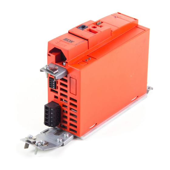
- Page 1 Drive Technology \ Drive Automation \ System Integration \ Services Manual ® MOVITRAC MC07B Functional Safety Edition 12/2011 19396414 / EN...
- Page 2 SEW-EURODRIVE—Driving the world...
-
Page 3: Table Of Contents
Contents Contents General Information .................... 4 How to use this documentation..............4 Underlying standards .................. 4 Structure of the safety notes ............... 5 Rights to claim under warranty ..............6 Exclusion of liability..................6 Copyright notice ..................6 Document content..................6 Other applicable publications .............. -
Page 4: General Information
SEW-EURODRIVE. Make sure you always use the latest documentation and software version. Our documentation is available in various languages for download from the SEW homepage. Consult SEW-EURODRIVE if you are unclear about any of the information in this documentation, or if you require further information. -
Page 5: Structure Of The Safety Notes
General Information Structure of the safety notes Structure of the safety notes 1.3.1 Meaning of signal words The following table shows the grading and meaning of the signal words for safety notes, notes on potential risks of damage to property, and other notes. Signal word Meaning Consequences if disregarded... -
Page 6: Rights To Claim Under Warranty
MOVITRAC MC07B units and to achieve the specified product characteristics and performance features. SEW-EURODRIVE assumes no liability for injury to persons or damage to equipment or property resulting from non-adherence to these operating instructions. In such cases, any liability for defects is excluded. -
Page 7: Integrated Safety Technology
Category 3 according to EN 954-1: 1996 • PL d according to EN ISO 13849-1: 2008 This was certified by TÜV Nord. Copies of the TÜV certificate can be obtained from SEW-EURODRIVE. Safe condition ® For safety-related operation of MOVITRAC MC07B, safe torque off is defined as safe condition (see STO safety function). -
Page 8: Schematic Representation - "Safety Concept For Movitrac ® B
Integrated Safety Technology ® Schematic representation – "safety concept for MOVITRAC B" ® Schematic representation – "safety concept for MOVITRAC B" S24V S0V24 L1 L2 L3 1797262603 Safety-related DC 24 V voltage supply Electrical isolation Voltage supply for control of power transistors Pulse width modulated signals for the output stage Phone: 800.894.0412 - Fax: 888.723.4773 - Web: www.clrwtr.com - Email: info@clrwtr.com Manual –... -
Page 9: Safety Functions
Integrated Safety Technology Safety functions Safety functions The following drive-related safety functions can be used: • STO (safe torque off according to EN 61800-5-2) by disconnecting the STO input. If the STO function is activated, the frequency inverter no longer supplies power to the motor for generating torque. - Page 10 Integrated Safety Technology Safety functions • SS1(c) (safe stop 1, function variant c according to EN 61800-5-2) by means of suitable external control (e.g. safety relay with delayed disconnection) The following sequence is mandatory: – Decelerate the drive using an appropriate brake ramp specified via setpoints. –...
-
Page 11: Restrictions
Integrated Safety Technology Restrictions Restrictions • Note that if the drive does not have a mechanical brake, or if the brake is defective, the drive may coast to a halt (depending on the friction and mass moment of inertia of the system). In case of regenerative loads, the drive can even accelerate. This must be taken into account in a risk assessment of the system/machine. -
Page 12: Safety Conditions
Safety Conditions Safety Conditions ® The requirement for safe operation is that the safety functions of MOVITRAC MC07B are properly integrated into an application-specific higher-level safety function. A system/machine-specific risk assessment must be carried out by the system/machine ® manufacturer and taken into account for operating the drive system with MOVITRAC MC07B. -
Page 13: Approved Devices
The following unit variants of MOVITRAC MC07B are permitted for safety-related applications: ® 3.1.1 MOVITRAC MC07B for a supply voltage of 3 × AC 380 – 500 V Power Size Type 0.55 MC07B0005-5A3-4-S0 0.75 MC07B0008-5A3-4-S0 MC07B0011-5A3-4-S0 MC07B0015-5A3-4-S0 MC07B0022-5A3-4-S0 MC07B0030-5A3-4-S0 MC07B0040-5A3-4-S0 MC07B0055-5A3-4-00 MC07B0075-5A3-4-00 MC07B0110-5A3-4-00... -
Page 14: Installation Requirements
Safety Conditions Installation requirements Installation requirements • For size 0 units of the type MC07B...-S0, an external 24 V supply must always be connected because the control electronics can only be powered in this way. • The safety-related DC 24 V supply voltage must be routed according to EMC guide- lines as follows: –... - Page 15 Safety Conditions Installation requirements • All connections (such as lines or data communication using bus systems) must already have been taken into account in the performance level of one of the sub- systems involved, or it must be possible that faults in the connections can be excluded or neglected.
-
Page 16: Requirements On The External Safety Controller
Safety Conditions Requirements on the external safety controller Requirements on the external safety controller [2] U 1593958923 [1] Safety relay with approval [2] DC 24 V voltage supply [3] Fuses in accordance with the manufacturer's specifications of the safety relay [4] Safety-related DC 24 V voltage supply [5] Reset button for manual reset [6] Approved EMERGENCY STOP actuating device... -
Page 17: Requirements On Startup
In this case, the test pulse must be applied with a time delay. – SEW-EURODRIVE recommends to switch off the 24 V supply at two poles. • The values specified for the safety controller must be strictly adhered to when de- signing the circuit. -
Page 18: Connection Variants
Connection Variants General information Connection Variants General information Generally, all the connection variants listed in this documentation are permitted for safety-relevant applications as long as the basic safety concept is met. This means you have to make sure that the DC 24 V safety inputs are operated by an external safety relay or a safety controller, thus preventing an automatic restart. -
Page 19: Requirements
Connection Variants Requirements Requirements 4.2.1 Use of safety relays The requirements of the manufacturers of safety relays (such as protecting the output contacts against welding) or other safety components must be strictly observed. For cable routing, the basic requirements apply as described in this publication. ®... -
Page 20: Disconnection Of A Single Drive
Connection Variants Disconnection of a single drive Disconnection of a single drive 4.3.1 STO according to PL d (EN ISO 13849-1) The procedure is as follows: • Recommendation: X12:1 and X12:4 are disconnected at the same time, e.g. in case of an emergency stop. - Page 21 With single-channel disconnection, certain fault assumptions have to be made and handled through fault exclusion. Observe the "Requirements" (page 19) chapter. SEW-EURODRIVE recommends to switch off the 24 V supply of the STO input X17 at two poles. Phone: 800.894.0412 - Fax: 888.723.4773 - Web: www.clrwtr.com - Email: info@clrwtr.com...
- Page 22 Connection Variants Disconnection of a single drive Binary control with safety PLC Higher-level Mains +24 V controller Start Standard Safe Emerg. stop Stop '0'=Ctrl. inhibit '1'=Ctrl. enable '0'=Stop '1'=START CW '0'=Rapid stop '1'=Enable 24VIO MC07B DGND VO24 SOV24 SVI24 4891654283 Fieldbus control with safety PLC Mains +24 V...
- Page 23 Connection Variants Disconnection of a single drive 4.3.2 SS1(c) according to PL d (EN ISO 13849-1) The procedure is as follows: • X12:1 must not be disconnected. • X12:4 is disconnected, e.g. in case of an emergency stop. • During the safety time interval t , the motor decelerates to a complete stop along the ramp.
- Page 24 With single-channel disconnection, certain fault assumptions have to be made and handled by fault exclusion. Observe the "Requirements" (page 19) chapter. SEW-EURODRIVE recommends to switch off the 24 V supply of the STO input X17 at two poles. Phone: 800.894.0412 - Fax: 888.723.4773 - Web: www.clrwtr.com - Email: info@clrwtr.com...
- Page 25 Connection Variants Disconnection of a single drive Binary control with safety PLC Higher-level Mains +24 V controller Start Standard Safe Emerg. stop Stop '0'=Ctrl. inhibit '1'=Ctrl. enable '0'=Stop '1'=START CW '0'=Rapid stop '1'=Enable 24VIO MC07B DGND VO24 SOV24 SVI24 4891654283 Fieldbus control with safety PLC Mains +24 V...
-
Page 26: Disconnection Of Group Drives
Disconnection of group drives ® This chapter describes how several MOVITRAC MC07B units are controlled safely. INFORMATION SEW-EURODRIVE does not recommend group disconnection via safety PLC. 4.4.1 Requirements ® For group drives, the 24 V safety inputs of several MOVITRAC MC07B inverters can be made available by a single safety relay. - Page 27 Connection Variants Disconnection of group drives 4.4.2 Implementing group disconnection with a safety relay Group disconnection with one safety relay ® The safety inputs of all MOVITRAC MC07B can be controlled with one safety relay. Control cabinet Safety ® relay (SG) MOVITRAC MC07B MC07B...
- Page 28 Connection Variants Disconnection of group drives 4.4.3 STO according to PL d (EN ISO 13849-1) The procedure is as follows: • Recommendation: X12:1 and X12:4 are disconnected at the same time, e.g. in case of an emergency stop. • The 24 V safety input X17 is disconnected. •...
- Page 29 Connection Variants Disconnection of group drives ® Example: Group disconnection with three MOVITRAC MC07B Mains Higher-level +24 V controller Start Emergency stop Stop Power supply connection Feedback emergency stop Safety '0'=Controller inhibit '1'=Controller enable relay '0'=Stop Reset '1'=START CW '0'=Rapid stop '1'=Enable 8 24VIO 9 GND...
-
Page 30: Technical Data
Technical Data Safety characteristics Technical Data ® The table below shows the technical data of MOVITRAC MC07B related to integrated ® safety technology. The technical data and approvals in the respective MOVITRAC MC07B operating instructions must also be observed. Safety characteristics Safety characteristics Tested safety class / underlying standards •... -
Page 31: Index
Index Index Approved devices ..........13 Requirements External safety controller ........16 Installation............14 Operation ............17 Checking the disconnection device......17 Startup ...............17 Connection variants ..........18 Right to claim under warranty ........6 Copyright notice ............6 Safe condition ............7 Disconnection of a single drive ......20 Safe stop 1, function variant c (SS1(c)) ....10 STO according to PL d (EN 13849-1) ....20 Safe torque off (STO) ..........9...
Need help?
Do you have a question about the MC07B0005-5A3-4-S0 and is the answer not in the manual?
Questions and answers
I would like to know how set up frequency values and change voltage