
Related Manuals for Rong Fu 45

Summary of Contents for Rong Fu 45
- Page 1 GEARED HEAD MILLING & DRILLING MACHINE MODEL 45 / 45N2F INSTRUCTION MANUAL 45/45N2F-090313-R4...
- Page 2 WARNING Some dust created by power sanding, sawing, grinding, drilling, and other construction activities contains chemicals known to the State of California to cause cancer, birth defects or other reprodrctive harm. Some examples of these chemical are: ‧Lead from lead-based paints. ‧Crystalline silica from bricks, cement and other masonry products.
-
Page 3: Table Of Contents
Table Of Contents Page No 1 Overall Aspect ………………………………………………………………… 2 2 Safety Rules For tools ………………………………………………………… 3 3 Specification …………………………………………………………………… 4 4 Features ……………………………………………………………………..… 5 5 Delivery & Installation …………………………………………………….. 6 6 Minimum Room Space For Machine Operation …………………………… 7 7 Use Of Main Machine Parts ……………………………………………….…... -
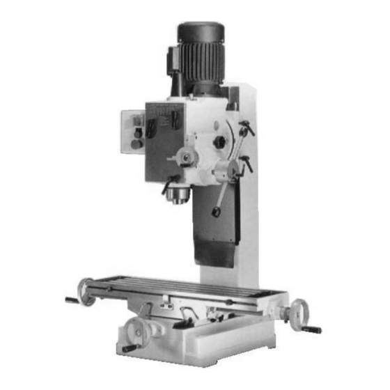
Page 4: Overall Aspect
Overall Aspect Motor Arbor bolt cover Knob Switch Rapid speed for drilling Speed lever Positive depth stop gauge Fine feed engagement control Drill fine feed control - calibrated Chuck guard Longitudinal feed - calibrated Head handle Two table stops Cross travel table lock Cross feed control Longitudinal travel... -
Page 5: Safety Rules For Tools
WARNING: FAILURE TO FOLLOW THESE RULES MAY RESULT IN SERIOUS PERSONAL INJURY As with all machinery there are certain hazards involved with operation and use of the machine. Using the machine with respect and caution will considerably lessen the possibility of personal injury. -
Page 6: Specification
Thank you for purchasing the RF-45 (N2F) COMPLEX Machine. If properly cared for and operated, this machine can provide you with years of accurate service. Please read this manual carefully before using your machine. -
Page 7: Features
Max. distance spindle nose 460mm(18") Length 925mm(36 ") to table R-8 or MT#3, Spindle taper Width 1190mm(46 ") NT#30 (Option) 1ø 1 HP (4 Pole) Spindle stroke 130mm(5") Vertical spindle motor 3ø 1HP Quill diameter 75mm(3") Packing 1 set / 1 case 60Hz Spindle Weight (NW/GW) -
Page 8: Delivery & Installation
1). Hand operation, which makes quick drilling. 2). Worm gear feed operation, which makes slow milling. (4) Bronze adjustable nuts, which adjust the thread clearance and reduce the wear. They also make screws rotated smoothly and increase the thread accuracy. (5) Whole column which makes this machine strong, stable, and also keep the high accuracy. -
Page 9: Minimum Room Space For Machine Operation
(8) Carefully lift the machine to a sturdy stand or work bench. For best performance, through bolt the machine to bench or stand. (9) Bolt the stand legs to the floor, while using a sturdy stand. Before Bolting The Machine To A Bench Or Stand Or Floor, The Unit Must Be Level In Both Directions. -
Page 10: Precaution For Operation
(d) When in emergency push button to sto p the machine. after clearing the trouble, release emergency button, re-start the machine by pushing the start button. 6. PRECAUTION FOR OPE RATION Check all parts for proper condition befo re operation; if normal safety precautions are notice carefully, this machine can provide you withstanding of accurate service. -
Page 11: Adjusting Table Slack And Compensate For Wear
UILL RETURN SPRING ADJUSTMENT: pring tension for return of spindle, after hole drilling, has been pre-set at the factory. No fur- ther adjustment should be attempted unless absolutely necessary. Adjustment will probably be required if a multiple drilling or tapping head is used. If adjustment is necessary, loosen lock scre while holding. -
Page 12: Clamping /Table Base And Machine Base
8. CLAMPING, TABLE BASE, AND MACHINE BASE (see Fig. 3) (1) When milling longitudinal feed, it is advisable to lock the cross feed table travel to insure the accuracy of your work. To do this, tighten the small leaf screw located on the right side of the table base. -
Page 13: To Change Tools
MACHINE IS STOPPED 60HZ 50HZ LEVERS 1260 1550 Table .1 10. TO CHANGE TOOLS (1) Removing Face Mill or Drill Chuck Arbor Loosen the arbor bolt (see fig. 4) at the top of the spindle shaft approximately 2 turns with a wrench. -
Page 14: Tapping Equipment
Collets Adapters and Sleeves 13. TAPPING EQUIPMENT This machine can be equipped with an electric switch for tapping operation clockwise or counter-clockwise, and the working depth also can be adjusted by the limit switch. (Electric switch will be installed according to your requirement, and you must pay the cost only.) 14. -
Page 15: Specification Of T Slot
15. SPECIFICATION OF T-SOLT The size of T-Solt on table as Fig 6: 16. MAINTAINING That's easier to keep machine in good condition or best performance by means of maintaining it at any time than remedy it after it is out of order. (1) Daily Maintenance (by operator) (a) Fill the lubricant before starting machine everyday. -
Page 16: Changing The Gear Box Oil
18. CHANGING THE GEAR BOX OIL Tilt the hard stock over as shown in fig.1. Open the oil drain plug to allow the oil to drain from the opening completely. Then lock the oil drain plug and turn the head to be upright position. Remove the oil filler plug fill the oil to the gear box until the oil lever reach the middle of oil fluid lever indicator. - Page 17 (g) If this machine with the tapping attachment, there is an aid plum screw fix on the motor mount in order to avoid the motor pulleys shake while turning. (3) The temperature of spindle bearing is too hot: (a) Grease is insufficient - Fill the grease. (b) The spindle beating is fixed too tight - turning with no speed and feel the tightness with hand.
- Page 18 (b) Dull drill – Sharpen drill and keep sharp. (c) Motor not building up to running speed. – Replace or repair motor. Check fuses in all three legs on three phase motors and replace if necessary. (d) Bad motor. – Replace motor. (11) Noisy operation: (a) Excessive vibration.
-
Page 19: Circuit Diagram
CIRCUIT DIAGRAM -17-... - Page 20 CIRCUIT DIAGRAM -18-...
-
Page 21: Power Down Feed Operation
POWER DOWN FEED OPERATION: 1. Firs, check the proper feed speed for the object the cutter. 2. By adjusting the shift dial “A”(see Fig2), You can obtain the speed you need. The shift dial can be operated during the machine running or when the machine is stopped by turning it on clockwise or counter-clockwise. -
Page 22: Parts Breakdowns & Parts Lists
-20-... - Page 23 -21-...
- Page 24 -22-...
- Page 25 -23-...
- Page 26 -24-...
- Page 27 PARTS LIST MODEL NO. 45 CODE NO PART NO DESCRIPTION SPECIFICATION QTY NOTE 2401011S Head Body Set 2401001-2 Main Shaft Cover 6101 MT3 M10xP1.5 Chuck Arbor Bolt 6101-1 MT3 M12xP1.75 Chuck Arbor Bolt 6101-2 MT3 W3/8"-16 Chuck Arbor Bolt 6101-3 MT3 W1/2"-12...
- Page 28 PARTS LIST MODEL NO. 45 CODE NO PART NO DESCRIPTION SPECIFICATION QTY NOTE 6193 Hex. Socket Headless Screw S008 1/4"x2"L Hex. Head Screw N003 1/4" Hex. Nut 6192 Position Set Bracket 61105S Spring Base Set S732 3/16"x3/4"L Cross Round Head Screw...
- Page 29 PARTS LIST MODEL NO. 45 CODE NO PART NO DESCRIPTION SPECIFICATION QTY NOTE 6145 Worm Cover S470 3/16"x3/8"L Hex. Socket Head Screw 6144S Micro Adjusting Indicator Set Metric 6144-1S Micro Adjusting Indicator Set Inch 6142-2S Handwheel Assembly 6142-2AS Handwheel Assembly...
- Page 30 PARTS LIST MODEL NO. 45 CODE NO PART NO DESCRIPTION SPECIFICATION QTY NOTE 6168 Punch Key 6187-1 Chuck 1/2-B16 6187 Chuck Switch For CE Only 260616S Chuck Guard Asbly For CE Only 260616AS Chuck Guard Asbly Optional 6628-1 Table 6229...
- Page 31 PARTS LIST MODEL NO. 45 CODE NO PART NO DESCRIPTION SPECIFICATION QTY NOTE 6215-1S Inch Acme Nut Asbly 2423001 Swivel Base 2402005S Metric Acme Screw Asbly 2402005AS Inch Acme Screw Asbly HD103 PT1/4"x3/8"L Plug 6241A Vise 2422001 Vertical Square Column...
- Page 32 PARTS LIST MODEL NO. 45 CODE NO PART NO DESCRIPTION SPECIFICATION QTY NOTE HS243 Hex. Socket Head Screw M8x25L HS250 Hex. Socket Head Screw M8x60L 6158S Head Handle Set 6027-1S Clamp Handle 2422045 Slide Base Flange HD511 Hex. Socket Flat Head Scvew HG005 ∮40x∮68x8t...
- Page 33 -31-...
- Page 34 -32-...
- Page 35 -33-...
- Page 36 -34-...
- Page 37 -35-...
- Page 38 -36-...
- Page 39 -37-...
- Page 40 PARTS LIST MODEL NO. 45N2F CODE NO PART NO DESCRIPTION SPECIFICATION QTY NOTE 2450002S Head Body Set 2401001-2 Main Shaft Cover 6101 MT3 M10xP1.5 Chuck Arbor Bolt 6101-1 MT3 M12xP1.75 Chuck Arbor Bolt 6101-2 MT3 W3/8"-16 Chuck Arbor Bolt 6101-3 MT3 W1/2"-12 Chuck Arbor Bolt 6101-4...
- Page 41 PARTS LIST MODEL NO. 45N2F CODE NO PART NO DESCRIPTION SPECIFICATION QTY NOTE 61103S Spring&Spring Cover W202 1/4"x1"x1.5t Spring Washer W003 1/4" Washer S471 1/4"x5/8L Hex. Socket Head Screw 6127 3/8"-16UNC-38L Screw Key N005 3/8" Hex. Nut 2421003 Handle Rod W002 1/2"x7/8"x2t Washer...
- Page 42 PARTS LIST MODEL NO. 45N2F CODE NO PART NO DESCRIPTION SPECIFICATION QTY NOTE 6122D MT3 M12-∮22 Cutter Arbor 6122 NT30 Cutter Arbor 6120A MT4 M12xP1.75 ∮25.4 Cutter Arbor Optional 2401194 MT4 M12xP1.75 ∮22 Cutter Arbor 6168 Punch Key Switch Optional 6186 Milling Cutter ∮25.4...
- Page 43 PARTS LIST MODEL NO. 45N2F CODE NO PART NO DESCRIPTION SPECIFICATION QTY NOTE 6213-1 Grip 6213-2 Grip 6151-1 T Screw 6213 Thumb Screw S414 5/16"x1"L Hex. Socket Head Screw W205 5/16" Spring Washer S418 5/16"x2-1/4"L Hex. Socket Head Screw 6215S Metric Acme Nut Asbly 6215-1S...
- Page 44 PARTS LIST MODEL NO. 45N2F CODE NO PART NO DESCRIPTION SPECIFICATION QTY NOTE 401-26 2450079 Speed Lever 401-27 HS512 M4x0.7x25L Cross Round Head Screw 401-28 290089 Spring 401-29 HB001 ∮8 or 5/16" Steel Ball 401-30 2450081A Gear Shaft 401-31 2450051 2450085A Bearing Spacer 2450088A...
- Page 45 PARTS LIST MODEL NO. 45N2F CODE NO PART NO DESCRIPTION SPECIFICATION QTY NOTE 420-3 2450023 Worm Gear 420-4 2450024 Clutch Key Base 420-5 HCS13 C-Retainer ring 420-6 2450096 Cluth Screw 420-7 2450095 Cluth Nut 420-8 2450027 Spring Pin 420-9 2450097 Clutch Key Pin 420-10 2450026...
- Page 46 PARTS LIST MODEL NO. 45N2F CODE NO PART NO DESCRIPTION SPECIFICATION QTY NOTE 2422036 Bushing HS291 M12x85L Hex. Socket Head Screw HCR04 C-Retaniner Ring 2422024 Worm Shaft 2422026 Worm Gear 2422030 Bearing 2422025 Support Flange HS243 Hex. Socket Head Screw M8x25L HS250 Hex.
- Page 47 Steel Ball HD001 ∮0.8x7L Spring 2401029S Gear Set 2401192A Bushing 2401031B Gear Shaft HCS07 C-Retaniner Ring 2401055 Gear 2401037S Gear HG004 ∮35x∮62x8t Oil Seal HCR08 C-Retaniner Ring CA6007ZZ 6007ZZ Ball Bearing (6007ZZ) 2401043B Gear Shaft 2401049S Gear Set - 45 -...
- Page 48 MANUFACTURER: ADDRESS: SERIAL No.: PLEASE WRITE DOWN THE SERIAL NO. ON THIS BLOCK FROM THE NAME PLATE AFTER YOU RECEIVE THIS MACHINE.
Need help?
Do you have a question about the 45 and is the answer not in the manual?
Questions and answers