Table of Contents
Advertisement
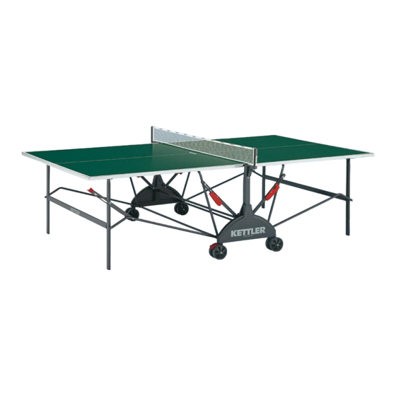
Kettler Stockholm Table Tennis Table Instructions
Models K-7122-490, K-7122-890, K-7162-490, K7162-890
Kettler Stockholm Table Tennis Table Unpacking & Moving Instructions
Models K-7122-500, K-7122-700, K-7162-500, K7162-700
Copyright ©2004 Robbins Specialties
Copyright ©2004 Robbins Specialties
Two people are needed to carry the box,
because of the weight and bulk.
When ready to unpack and to remove the
contents from the carton, turn the carton 90
degrees from its upright position. Open the left
and right ends of the carton. With one person
pushing on the contents from one side, have
another person pull from the opposite side until
contents are removed from the carton.
When carrying the table up or down stairs, it is
advisable to remove the plastic wrap from the
table tops and carry each piece individually to
reduce the weight.
The following pages will provide a breakdown of
the parts contained within the carton.
- 1 -
Advertisement
Table of Contents

Related Manuals for Kettler K-7122-490


Summary of Contents for Kettler K-7122-490
- Page 1 Kettler Stockholm Table Tennis Table Instructions Models K-7122-490, K-7122-890, K-7162-490, K7162-890 Copyright ©2004 Robbins Specialties Kettler Stockholm Table Tennis Table Unpacking & Moving Instructions Models K-7122-500, K-7122-700, K-7162-500, K7162-700 Copyright ©2004 Robbins Specialties Two people are needed to carry the box, because of the weight and bulk.
- Page 2 Kettler Stockholm Table Tennis Table Parts Inventory Models K-7122-500, K-7122-700, K-7162-500, K7162-700 Copyright ©2004 Robbins Specialties Master Carton Size 5’2” x 4’8” MASTER CARTON CONTENTS #PRE-1 WHEEL PACK CORRUGATED HARDWARE TABLE TOP HALVES PREASSEMBLY 7 ½” x 21” ENVELOPE 4’6” x 5’...
- Page 3 WHEEL PACK CONTENTS (Below is depicted the contents of one wheel pack) WHEEL FOR NON LOCKING CASTER WHEEL FOR LOCKING CASTER 4” 4” 4 EACH 4 EACH USED IN: STEP 3 (4 EA) USED IN: STEP 4 (4EA) LOCKING WHEEL PIVOT RED WHEEL LOCK NON LOCKING WHEEL PIVOT 2 EACH...
- Page 4 CORRUGATED HARDWARE ENVELOPE Size 4’ x 37 3/4” CORRUGATED HARDWARE ENVELOPE CONTENTS #PRE-3 #PRE-2 CENTER PIVOT PREASSEMBLY T-SHAPED CENTER SUPPORT PREASSEMBLY 18 ½” HEIGHT 24 ¾” x 21 ½” 2 EACH 2 EACH USED IN: STEP 8 (2 EA) USED IN: STEP 2 (2 EA) NET POST CENTER SUPPORT COVER 10”...
- Page 5 Size 8 1/2” x 10” HARDWARE PACK NO. 1 CONTENTS #HDW-12 #HDW-13 #HDW-15 #HDW-23 PLASTIC END INSERT FOR LEG 16 MM WASHERS 25 MM 8M BOLT CAP M5 NUT CROSS BRACE 24 EACH WASHERS 8 EACH 4 EACH 4 EACH USED IN: STEP 2 (8 EA);...
- Page 6 Size 10” x 12 1/2” HARDWARE PACK NO. 2 CONTENTS #HDW-27 #HDW-29 ADAPTER FOR NET POST LOCK END CAPS 2 EACH 2 EACH USED IN: STEP 5 (2 EA) USED IN: STEP 11 (2 EA) HARDWARE PACK NO. 2A HARDWARE PACK NO. 2B PARTS BAG WITHIN PACK NO.
- Page 7 Size 8 1/2” x 6” HARDWARE PACK NO. 2A CONTENTS #HDW-8 #HDW-7 EXTRA PARTS – DO NOT USE M6x49 BOLTS M6x58 BOLTS 4 5/16” BOLTS 1 15/16” LENGTH 2 1/4” LENGTH USED IN: NOT USED 4 EACH 2 EACH USED IN: STEP 14 (4 EA) USED IN: STEP 13 (2 EA) #HDW-9 #HDW-17...
- Page 8 Size 7” x 9” HARDWARE PACK NO. 2B CONTENTS #HDW-3 #HDW-6 #HDW-4 M8x60 BOLTS M5x65 BOLTS M6x45 BOLTS 2 3/8” LENGTH 1 15/16” LENGTH 1 3/8” LENGTH 6 EACH 4 EACH 4 EACH USED IN: STEP 9 (2 EA); STEP 11 (4 EA) USED IN: STEP 8 (4 EA) USED IN: STEP 6 (4 EA) #HDW-13...
- Page 9 Size 6” x 11” HARDWARE PACK NO. 3 CONTENTS INCLUDED TOOLS NET ASSEMBLY PARTS 1 EACH PHILLIPS HEAD SCREW DRIVER 1 EACH 1 EACH WRENCH (13, 10, 8MM) USED IN: STEP 16 (1 EA) 1 EACH WRENCH WITH ROD (10, 13MM) - 9 -...
- Page 10 Kettler Stockholm Table Tennis Table Assembly Instructions Models K-7122-500, K-7122-700, K-7162-500, K7162-700 Copyright ©2004 Robbins Specialties Part 1: CENTER SUPPORT ASSEMBLY Step #1 – WHEEL LOCK ASSEMBLY REQUIRED PARTS – 2 Sets INSTRUCTIONS PART # DESCRIPTION Slide #34 (RED WHEEL LOCK) down over #32 (LOCKING...
- Page 11 Step #2 – CENTER SUPPORT ASSEMBLY REQUIRED PARTS – 2 Sets INSTRUCTIONS PART # DESCRIPTION Place #6 (T-SHAPED CENTER SUPPORT) with the flange 1 ea WHEEL LOCK ASSEMBLY facing away. (Please refer to diagram above.) Slide #HDW-1 (From Step 1) (M8X125 BOLT) though #HDW-12 (16MM WASHER), then 1 ea #PRE-2...
- Page 12 Step #3 – CENTER SUPPORT ASSEMBLY – PIVOT WHEEL REQUIRED PARTS – 2 Sets INSTRUCTIONS PART # DESCRIPTION Slide #HDW-5 (M8x110 BOLT) though #HDW-12 1 ea CENTER SUPPORT ASSEMBLY (16MM WASHER), then though #8 (WHEEL FOR (From Step 2) NON LOCKING CASTER), then though another 2 ea WHEEL FOR NON LOCKING #HDW-12 (16MM WASHER).
- Page 13 Step #4 – CENTER SUPPORT ASSEMBLY – LOCKING WHEEL REQUIRED PARTS – 2 Sets INSTRUCTIONS PART # DESCRIPTION Slide #HDW-5 (M8x110 BOLT) though #HDW-12 1 ea CENTER SUPPORT ASSEMBLY (16MM WASHER), then though #35 (WHEEL FOR (From Step 3) LOCKING CASTER), then though another #HDW-12 2 ea WHEEL FOR LOCKING CASTER (16MM WASHER).
- Page 14 tep #5 – CENTER SUPPORT ASSEMBLY – NET POST (A) REQUIRED PARTS – 2 Sets INSTRUCTIONS PART # DESCRIPTION With the raised sides of #27 (ADAPTER FOR NET POST) 1 ea CENTER SUPPORT facing #17 (NET POST), slide the adapter ASSEMBLY onto the two post flanges.
- Page 15 Step #6 – CENTER SUPPORT ASSEMBLY – NET POST (B) REQUIRED PARTS – 2 Sets INSTRUCTIONS PART # DESCRIPTION Slide the #HDW-22 (3MM SQUARE NUT) into the two 1 ea CENTER SUPPORT notches at the base of the #17 (NET POST) on the CENTER ASSEMBLY SUPPORT ASSEMBLY.
- Page 16 Step #7 – CENTER SUPPORT ASSEMBLY – For Outdoor Tables ONLY (For Indoor Table Assembly Skip This Step) REQUIRED PARTS – 2 Sets INSTRUCTIONS PART # DESCRIPTION PLEASE NOTE THIS STEP IS ONLY FOR THE OUTDOOR 1 ea #PRE-3 CENTER PIVOT ASSEMBLY TABLES.
- Page 17 Step #8 – CENTER SUPPORT & PIVOT ASSEMBLY REQUIRED PARTS – 2 Sets INSTRUCTIONS PART # DESCRIPTION Position #PRE-3 (CENTER PIVOT ASSEMBLY) with the 1 ea CENTER SUPPORT bottom two pivot screws facing the support flanges of the ASSEMBLY CENTER SUPPORT ASSEMBLY as shown in the above (From Step 6) diagram.
- Page 18 Part 2: CHASSIS ASSEMBLY Step #9 – CENTER SUPPORT CHASSIS ASSEMBLY REQUIRED PARTS – 1 Sets INSTRUCTIONS PART # DESCRIPTION Position the two CENTER SUPPORT ASSEMBLIES with the connected CENTER PIVOT ASSEMBLY parts facing each 2 ea CENTER SUPPORT ASSEMBLY other.
- Page 19 Step #10 –CHASSIS SUPPORT ASSEMBLY REQUIRED PARTS – 2 Sets INSTRUCTIONS PART # DESCRIPTION Place #14 (CENTER SUPPORT CROSS BRACE) on a 1 ea CENTER SUPPORT CROSS BRACE flat surface. Slide the bottom of #PRE-4 (LOCKING SIDE BRACE ASSEMBLY) onto the right side of #14 (CENTER SUPPORT CROSS BRACE).
- Page 20 Step #11 –CHASSIS & TABLE TOP ASSEMBLY REQUIRED PARTS – 2 Sets INSTRUCTIONS - Two people are needed for this step. PART # DESCRIPTION 1 ea #PRE-1 TABLE TOP HALF - Lift the #PRE-1 (TABLE TOP HALF – PREASSEMBLY) and PREASSEMBLY place the bottom table edge into the CENTER SUPPORT 1 ea...
- Page 21 Step #12 –END LEG CROSS BRACE ASSEMBLY REQUIRED PARTS – 2 Sets INSTRUCTIONS PART # DESCRIPTION Slide #HDW-23 (5MM SQUARE NUT) into #22 (PLASTIC 1 ea CROSS BRACE FOR TABLE END INSERT FOR END LEG CROSS BRACE). END LEGS With the back side of #21 (CROSS BRACE FOR TABLE END LEGS) facing up (not the side with logo imprint), slide #22 (PLASTIC END INSERT) into the end of #21 (CROSS 1 ea...
- Page 22 Click Here to go to http://www.robbinstabletennis.com/stockholm-assembly-video.html For a Video Demonstration of This Assembly Step...
- Page 23 Click Here to go to http://www.robbinstabletennis.com/stockholm-assembly-video.html For a Video Demonstration of This Assembly Step...
- Page 24 INSTRUCTIONS FOR UNFOLDING THE TABLE To unfold the table, first unlock the left side. To do this, push down on the top toggle of the lock so that it swings down and clicks into place. Then go to the right side lock. While supporting the table half, grip the bottom of the lock and squeeze until the top bolt is released.
- Page 25 Step #15 – ATTACHING THE CENTER SUPPORT COVER REQUIRED PARTS – 2 Sets INSTRUCTIONS PART # DESCRIPTION 1 ea TABLE ASSEMBLY (from Step 14) Align the flanges on #16 (CENTER SUPPORT COVER) 1 ea CENTER SUPPORT COVER with the three holes on the table’s center support just above the casters.
- Page 26 INSTRUCTIONS FOR FOLDING THE TABLE Press the locking lever up and lift the table half upwards. Continue to press the lever during the first part of the upward motion. Lift up from the edge of the table and walk it forward until it locks into place in the folded position.
- Page 27 Step #16 – NET INSTALLATION REQUIRED PARTS – 1 Set INSTRUCTIONS PART # DESCRIPTION TABLE ASSEMBLY Insert the TENSION ROD HOOK into the side of the (from Step 15) NET. Take the TENSION TOP STRING from the top 1 ea NET PARTS of the NET and tie it to the WHITE PLASTIC TENSION ADJUSTMENT TAB.
- Page 28 - 28 -...
- Page 29 KETTLER STOCKHOLM TABLE TENNIS TABLE PARTS LIST REF NO. DESCRIPTION PART NO. FOUND IN STEP #1: REQUIRED PARTS RED WHEEL LOCK 70130816 Wheel Pack BLACK PIVOT FOR LOCKING CASTER 70130815 Wheel Pack HDW-19 METAL PINS Pack No.1 STEP #2: REQUIRED PARTS...
- Page 30 KETTLER STOCKHOLM TABLE TENNIS TABLE PARTS LIST REF NO. DESCRIPTION PART NO. FOUND IN STEP #11: REQUIRED PARTS CROSS BRACE INSERT 70130525 Pack No. 2B HDW-3 M8x60 BOLT Pack No. 2B HDW-13 25MM WASHER Pack No. 2B LOCK END CAPS 70130530 Pack No.
Need help?
Do you have a question about the K-7122-490 and is the answer not in the manual?
Questions and answers