
Related Manuals for Tektronix TCP0020


Summary of Contents for Tektronix TCP0020
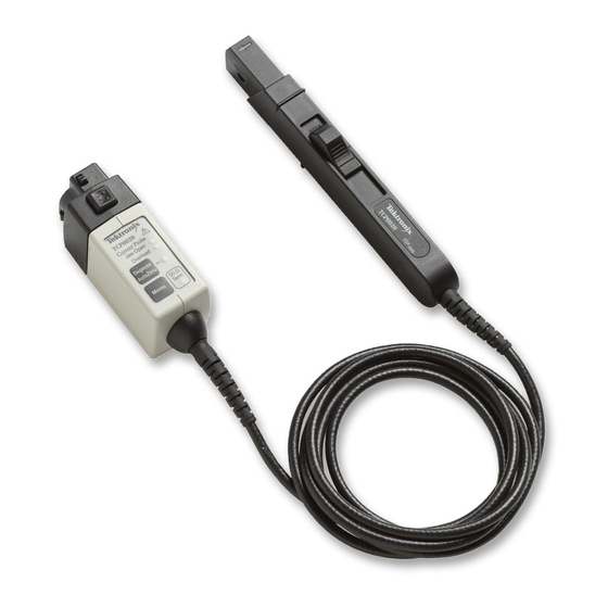
- Page 1 TCP0020 & TCP2020 50 MHz, 20 Amp AC/DC Current Probes Instruction Manual *P071300200* 071-3002-00...
- Page 3 TCP0020 & TCP2020 50 MHz, 20 Amp AC/DC Current Probes Instruction Manual Revision A www.tektronix.com 071-3002-00...
- Page 4 Copyright © Tektronix. All rights reserved. Licensed software products are owned by Tektronix or its subsidiaries or suppliers, and are protected by national copyright laws and international treaty provisions. Tektronix products are covered by U.S. and foreign patents, issued and pending. Information in this publication supersedes that in all previously published material.
- Page 5 Warranty Tektronix warrants that this product will be free from defects in materials and workmanship for a period of one (1) year from the date of shipment. If any such product proves defective during this warranty period, Tektronix, at its option, either will repair the defective product without charge for parts and labor, or will provide a replacement in exchange for the defective product.
-
Page 7: Table Of Contents
TCP0020 Probe ........... - Page 8 Table of Contents Functional Check ......................... . Accessories and Options .
- Page 9 Table of Contents Performance Verification ........................Equipment Required .
- Page 10 Table of Contents 20 A Current Probes Instruction Manual...
-
Page 11: General Safety Summary
General safety summary General safety summary Review the following safety precautions to avoid injury and prevent damage to this product or any products connected to it. To avoid potential hazards, use this product only as specified. Only qualified personnel should perform service procedures. While using this product, you may need to access other parts of a larger system. - Page 12 General safety summary Do not connect a current probe to any wire that carries voltages above the current probe voltage rating. Power disconnect. The power cord disconnects the product from the power source. Do not block the power cord; it must remain accessible to the user at all times.
- Page 13 General safety summary Terms in this manual These terms may appear in this manual: Warning statements identify conditions or practices that could result in injury or loss of life. WARNING. Caution statements identify conditions or practices that could result in damage to this product or other property. CAUTION.
- Page 14 General safety summary The following symbol(s) may appear on the product: viii 20 A Current Probes Instruction Manual...
-
Page 15: Service Safety Summary
Service safety summary Service safety summary Only qualified personnel should perform service procedures. Read this Service safety summary and the General safety summary before performing any service procedures. Do not service alone. Do not perform internal service or adjustments of this product unless another person capable of rendering first aid and resuscitation is present. -
Page 16: Compliance Information
Compliance Information Compliance Information This section lists the EMC (electromagnetic compliance), safety, and environmental standards with which the instrument complies. EMC Compliance EC Declaration of Conformity – EMC (Applies Only to the TCP2020 Probe) Meets intent of Directive 2004/108/EC for Electromagnetic Compatibility. Compliance was demonstrated to the following specifications as listed in the Official Journal of the European Communities: EN 61326-1 2006. - Page 17 Compliance Information European contact. Tektronix UK, Ltd. Western Peninsula Western Road Bracknell, RG12 1RF United Kingdom This product is intended for use in nonresidential areas only. Use in residential areas may cause electromagnetic interference. Emissions which exceed the levels required by this standard may occur when this equipment is connected to a test object.
-
Page 18: Certifications And Compliances
Compliance Information Certifications and Compliances EC Declaration of Conformity - Low Voltage Compliance was demonstrated to the following specification as listed in the Official Journal of the European Communities: Low Voltage Directive 2006/95/EC. EN 61010-1:2001. Safety requirements for electrical equipment for measurement control and laboratory use. EN 61010-2-032:2002. - Page 19 Compliance Information Additional Compliance IEC 61010-1:2001. Safety requirements for electrical equipment for measurement, control, and laboratory use. IEC 61010-2-032:2002. Particular requirements for handheld current clamps for electrical measurement and test equipment. Equipment Type Measurement Pollution Degree Descriptions A measure of the contaminates that could occur in the environment around and within a product. Typically the internal environment inside a product is considered to be the same as the external.
- Page 20 Compliance Information Polution Degree 3. Conductive pollution, or dry, nonconductive pollution that becomes conductive due to condensation. These are sheltered locations where neither temperature nor humidity is controlled. The area is protected from direct sunshine, rain, or direct wind. Polution Degree 4. Pollution that generates persistent conductivity through conductive dust, rain, or snow. Typical outdoor locations.
-
Page 21: Environmental Considerations
This symbol indicates that this product complies with the applicable European Union requirements according to Directives 2002/96/EC and 2006/66/EC on waste electrical and electronic equipment (WEEE) and batteries. For information about recycling options, check the Support/Service section of the Tektronix Web site (www.tektronix.com). - Page 22 Compliance Information 20 A Current Probes Instruction Manual...
-
Page 23: Preface
This manual describes the installation and operation of the TCP0020 & TCP2020 current probes. Basic probe operations and concepts are presented in this manual. You can also access the Tektronix Web site for this document and other related information. Documentation... -
Page 24: Returning The Probe For Servicing
Preface Returning the Probe for Servicing If your probe requires servicing, you must return the probe to Tektronix. If the original packaging is unfit for use or not available, use the following packaging guidelines: Preparation for Shipment 1. Use a corrugated cardboard shipping... -
Page 25: Key Features
Key Features Key Features Use the TCP0020 & TCP2020 current probes to make accurate measurements from DC to 50 MHz. The probes combine proven Hall-effect technology with the Tektronix TekVPI oscilloscope interface. Key features include: TCP0020 Current Probe AC coupling (on TekVPI oscilloscopes that... - Page 26 Key Features TCP2020 Current Probe >50 MHz bandwidth, <7 ns rise time AC/DC measurement capability 20 A RMS continuous rating (de-rated with frequency) 100 A peak pulse current (pulse widths <10 μs) 1% DC accuracy (typical) One-button degauss 150V CAT II (Bare wire), 300V CAT II (Insulated wire) External power supply allows use on any 1 MΩ-input measuring instrument...
-
Page 27: Installation
Installation Installation TCP0020 Probe 1. Slide the TCP0020 probe into the oscilloscope input. The probe snaps in when fully engaged. All of the probe LEDs light briefly for a quick visual check, and then the Degauss LED flashes red to indicate a degauss is required. - Page 28 Installation TCP2020 Probe 1. Align the BNC connector on the probe to the oscilloscope input connector. 2. Push in the probe connector and turn it to the right to lock it in place. 3. Connect the AC adapter to a line source and then connect it to the probe.
-
Page 29: Degaussing The Probes
Installation Degaussing the Probes 1. After the TCP0020 probe is connected to the oscilloscope, the multicolor Degauss/AutoZero status LED flashes red to indicate a degauss is required. The oscilloscope screen display may also prompt you to degauss the probe. The TCP2020 probe does not indicate... - Page 30 Degauss/AutoZero status LED flashes red. 4. The multicolor Degauss/AutoZero status LED on the TCP0020 probe glows green to indicate a successful degauss routine was run, and that the probe is in normal operating mode.
- Page 31 Installation Quick Tip To maintain measurement accuracy, degauss your probe in each of these cases: After you turn on the measurement system and allow a 20-minute warm-up period Before you connect the probe to a conductor Whenever a current or thermal overload condition occurs Whenever you subject the probe to a strong external magnetic field...
-
Page 32: Controls And Indicators
Controls and Indicators Controls and Indicators The TCP0020 and TCP2020 probes share the same probe head design and some common features. Controls and indicators that are unique to each probe model are covered in the separate sections that follow. Probe Head Slider and Conductor Jaw 1. - Page 33 Controls and Indicators 4. Safe handling zone – keep fingers behind demarcations when taking measurements. WARNING. To avoid electrical shock, do not access the area beyond the safe handling zone (indicated by the shaded area) when you take measurements. WARNING. To prevent probe damage, do not drop the probe or subject it to impact.
-
Page 34: Tcp0020 Probe
Controls and Indicators TCP0020 Probe This section describes the controls and indicators for the TCP0020 probe. The following section covers the TCP2020 probe. (See page 20, TCP2020 Probe.) Power On Indication When the TCP0020 probe is powered on, all of the indicator LEDs light briefly, and then the Degauss/AutoZero LED on the probe flashes... - Page 35 Controls and Indicators Jaw Open LED 1. The Jaw Open LED glows when the probe slider is unlocked. 2. Push the probe slider forward to lock it and to turn off the LED. In the locked position, you can degauss the probe, or when connected to a conductor, accurately measure current.
- Page 36 Controls and Indicators Overload LED The Overload LED alerts you that the probe specifications are being exceeded. When the LED glows red, the maximum input continuous current limit has been exceeded. CAUTION. Do not subject the probe to conditions that cause the Overload LED to light for extended periods.
- Page 37 Controls and Indicators Degauss/AutoZero Button The Degauss/AutoZero button degausses and nulls any DC offset in the probe. To degauss the probe, do the following: 1. Disconnect the probe from any conductors, and then close and lock the slider. 2. Press the Degauss/AutoZero button to initiate the degauss routine.
- Page 38 Controls and Indicators Degauss/AutoZero LED When the multicolor Degauss/AutoZero status LED flashes red, you must degauss the probe. The Degauss/AutoZero function also nulls any DC offset in the probe. If the LED flashes orange, you should degauss the probe. The DC gain and offset errors are not guaranteed when this LED flashes orange.
- Page 39 Controls and Indicators 50 Ω Term LED This LED lights when the output signal path in the probe is actively terminated to 50 Ω. For the LED to correctly indicate the probe termination, you must degauss the probe after you connect it to the oscilloscope, or if you change the oscilloscope termination while the probe is connected to the oscilloscope.
- Page 40 Controls and Indicators Menu Button Press the Menu button on the TCP0020 probe to access additional probe functions, such as probe offset and deskew. The following menus may appear on the oscilloscope screen, depending on the model. An MSO/DPO4000 series oscilloscope is used in this example.
- Page 41 Controls and Indicators Menu-Driven Probe Functions The following probe functions are available through menu screens on many Tektronix oscilloscopes. An MSO/DPO4000 series oscilloscope is used in these examples. Fine Scale. This feature allows you to adjust the vertical mA/div setting to a custom scale that is between the fixed 1–2–5 scales on many...
- Page 42 Controls and Indicators Probe Setup. The Probe Setup menu displays the current range and attenuation (20 amperes and 10X for the TCP0020 and TCP2020 probes). Side-bezel buttons allow you to run the Degauss and AutoZero routines. The buttons also display the degauss status of the probe.
- Page 43 Controls and Indicators Deskew. To deskew the TCP0020 and TCP2020 probes to other probes, select this function and connect the probes to the optional deskew fixture. (See page 30, Deskew/Calibration Fixture.) The deskew procedure measures the channel-to-channel delay time, including the probes, and provides manual and automatic steps to align the delay (skew).
-
Page 44: Tcp2020 Probe
Controls and Indicators TCP2020 Probe This section describes the controls and indicators for the TCP2020 probe. Power LED The TCP2020 probe is powered by an external DC power supply that is included with the probe. NOTE. The probe will pass through AC signals without the external power supply connected, but the performance is not guaranteed. - Page 45 Controls and Indicators Degauss Button The Degauss button degausses and nulls any DC offset in the probe. To degauss the probe, do the following: 1. Disconnect the probe from the current source. 2. Close and lock the slider. 3. Press the Degauss button to initiate the degauss routine.
- Page 46 Controls and Indicators Jaw Open LED 1. When the Jaw Open LED glows, the probe slider is unlocked. 2. Push the probe slider forward to lock it and to turn off the LED. In the locked position, you can degauss the probe, or when connected to a conductor, accurately measure current.
- Page 47 Controls and Indicators Balance Control Use the Balance control (thumb wheel) to make minor adjustments to DC offsets present on the probe output. To use the control: 1. Disconnect the probe from the current source. 2. Lock the probe slider closed. 3.
-
Page 48: Functional Check
Functional Check Functional Check The following procedure checks that your probe is functioning properly. To verify that your probe meets the warranted specifications, refer to the Performance Verification procedures. (See page 61.) The probe jaw opening accommodates insulated conductors with a diameter of 5.0 mm or less. Do not insert CAUTION. -
Page 49: Accessories And Options
Accessories and Options Accessories and Options This section lists the standard and optional accessories available for the probe, and provides information on how to use the accessories. Specifications are provided where appropriate so that you can choose the accessory that best fits your needs. 20 A Current Probes Instruction Manual... -
Page 50: Standard Accessories
1. Fasten the small clip to the ground stub on the probe body. 2. Clip the alligator clip to your circuit ground. 3. Attach the probe to your circuit. Reorder Tektronix part number: 196-3521-xx, qty. 1 20 A Current Probes Instruction Manual... - Page 51 2. Close the carrying case to transport the accessories to another location or for storage. Reorder Tektronix part number: 016-1952-xx DC Power Supply (TCP2020 Only) The TCP2020 probe requires an external DC power supply for proper operation.
- Page 52 Reorder Tektronix part number: 071-3002-xx Manuals in the languages listed below are available for this product. Other languages may also be available; check the Tektronix Web site at www.tektronix.com/manuals. (Japanese) (Simplified Chinese) 20 A Current Probes Instruction Manual...
-
Page 53: Optional Accessories
fixture fits in the jaw of the current probe. To use the current loop, follow the procedure for the specific task that you are performing (for example, Performance Verification or Adjustments). Order Tektronix part number: 067-2396-xx 20 A Current Probes Instruction Manual... - Page 54 The deskew procedures compensate for gain errors and timing differences between current and voltage probes. Refer to your oscilloscope manual or fixture documentation for instructions. Order Tektronix part number: 067-1686-xx 20 A Current Probes Instruction Manual...
-
Page 55: Options
Accessories and Options Options Service Options Option C3. Calibration Service 3 years Option C5. Calibration Service 5 years Option D1. Calibration Data Report Option D3. Calibration Data Report, 3 years (with Option C3) Option D5. Calibration Data Report, 5 years (with Option C5) Option R3. -
Page 56: Basic Operation
Basic Operation Basic Operation Do not force conductors larger than 5.0 mm (0.20 in) into the probe jaws. Damage to the probe may result. The mating CAUTION. surfaces of the probe head transformer are precision-polished and should be handled with care. Measurements may be degraded by dirt on the mating surfaces of the probe head transformer. - Page 57 Basic Operation Grounding the Probe Use the ground lead to improve EMI rejection at high frequencies. 1. Clip the ground lead to the ground post at the bottom of the probe head. 2. Connect the alligator end of the clip to the circuit ground.
-
Page 58: Probing Principles
Probing Principles Probing Principles The following information is provided to help you use the full potential of your current probe. Degaussing a Probe with an Unpowered Conductor in the Jaws You can degauss your current probe while a conductor of an unpowered circuit is clamped in the jaws. The advantage of degaussing with an unpowered circuit is that any offset from stray DC magnetic fields is compensated. -
Page 59: Measuring Differential Current
Probing Principles Measuring Differential Current To simplify your differential or null current measurements, you can place two conductors in one current probe. WARNING. When you are taking measurements on uninsulated conductors, do not exceed the 150 V CAT II voltage limit of the probe. - Page 60 Probing Principles 1. Orient the two conductors under test so that the polarities (+ and –) oppose each other. 2. Clamp the current probe around the two conductors. Be careful not to pinch a conductor in the probe jaws. 3. Measure the current. Conventional current flows from positive to negative.
-
Page 61: Extending Current Range
Probing Principles 4. To adjust for a current null, adjust the current in one of the conductors until the DC component of the displayed measurement is zero. Extending Current Range If your measurement exceeds the maximum current rating of the connected probe, you can extend the AC and DC current ranges without exceeding specified limits by using the following methods. - Page 62 Probing Principles WARNING. Do not put more than one uninsulated conductor at a time in the probe jaws. An uninsulated conductor is any conductor without insulation or without insulation rated for the voltage present on the conductor under test. To supply additional bucking current: 1.
- Page 63 Probing Principles To increase the value of the bucking current: 1. Wind multiple turns of the second conductor around the probe. The bucking current is equal to the current flowing in the conductor, multiplied by the number of turns wound around the probe. For example, if the second conductor has a current of 100 mA DC and is wrapped around the probe five times, the DC bucking current is...
-
Page 64: Increasing Sensitivity
Probing Principles Increasing Sensitivity If you are measuring DC or low-frequency AC signals of very small amplitudes, you can increase measurement sensitivity of your Current Probe by doing the following: 1. Wind several turns of the conductor under test around the probe as shown. The signal is multiplied by the number of turns around the probe. -
Page 65: Common Mode Noise/Magnetic Field Errors
Probing Principles Common Mode Noise/Magnetic Field Errors Common-mode noise at high frequencies and strong magnetic fields on the supply side of your circuit can cause measurement errors. To avoid this: 1. Measure on the low or ground side of your circuit. -
Page 66: Ac And Dc Coupling
Probing Principles AC and DC Coupling You can couple the signal input to the oscilloscope with either DC or AC coupling. DC coupling shows both the DC and AC measurement components. AC coupling removes the DC component from the displayed signal. Use your oscilloscope controls to change the coupling. -
Page 67: Maximum Current Limits
Probing Principles Maximum Current Limits Current probes have three maximum current ratings: pulsed, continuous, and Ampere-second product. Exceeding any of these ratings can saturate the probe core, which magnetizes the core and causes measurement errors. Refer to the specifications for the maximum current ratings of the probe. - Page 68 Probing Principles Ampere-Second Product is the maximum width of pulsed current that you can measure when the pulse amplitude is between the maximum continuous and maximum pulsed current specifications. The maximum continuous specification varies by frequency. To determine if your measurement exceeds the Ampere-second product, you must first determine the maximum allowable pulse width or maximum allowable pulse amplitude, as...
- Page 69 Probing Principles Maximum Allowable Pulse Width To determine the maximum allowable pulse width do the following: 1. Measure the peak current of the pulse. 2. Divide the Ampere-second (or Ampere-microsecond) specification for the probe by the measured peak current of the pulse: The quotient is the maximum allowable pulse width (PW 3.
- Page 70 For example, the TCP0020 and TCP2020 probes have a maximum Ampere-second product of 1000 A-μs. If a pulse measured with the probe has a width of 11 μs, the maximum allowable peak current would be 1000 A-μs...
-
Page 71: Application Examples
Application Examples Application Examples This section explains ways to use your probe in common troubleshooting tasks and how to extend the use of your measurement system. 20 A Current Probes Instruction Manual... -
Page 72: Inductance Measurements
Application Examples Inductance Measurements You can use the current probe to measure the inductance of coils that have either a low-impedance or high-impedance pulse source of a known value. Low-Impedance Pulse Sources This figure shows a constant-voltage pulse generator of extremely low output impedance connected to an inductor that has low resistance. - Page 73 Application Examples 4. Measure the current ramp. The inductance is effectively defined by the slope of the current ramp shown here. 5. Calculate the inductance using the following formula: where: L is the inductance in henries, E is the voltage of the pulse generator, dt is the change in time, and di is the change in current.
- Page 74 Application Examples High-Impedance Pulse Sources If the pulse source has a higher impedance of known resistance, such that the output voltage drops as the current increases, the inductance of a coil can be calculated by the time constant of the charge curve. The current ramp shows how the values for the inductance formula are obtained.
-
Page 75: Measuring Inductor Turns Count
Application Examples Measuring Inductor Turns Count To obtain an approximate turns count of an inductor, do the following: 1. Connect the inductor to a current limited source, as shown. 2. Measure the input current on one of the inductor leads. 3. - Page 76 Application Examples For a more precise turns count, you need a coil with a known number of turns to use as a reference. Do the following: 1. Repeat steps 1 and 2 above and make the following changes: 2. Insert the reference coil into the current probe.
-
Page 77: Specifications
The probe has been calibrated at an ambient temperature of 23 °C ±5 °C. The probe is connected to a host instrument with an input impedance of 1 M Ω. The TCP0020 probe specifications are also valid on host instruments with an input impedance of 50 Ω. -
Page 78: Typical Characteristics
(See Figure 3 on page 57.) TCP0020 with 50 Ω oscilloscope termination 50 A maximum peak pulse (pulse width ≤20 μs) TCP0020 & TCP2020 with 1 MΩ oscilloscope termination 100 A maximum peak pulse (pulse width ≤10 μs) Displayed RMS noise ≤1.0 mA RMS (limit measurement bandwidth to 20 MHz) - Page 79 Specifications Figure 1: Frequency derating (continuous peak current versus frequency) 20 A Current Probes Instruction Manual...
- Page 80 Specifications Figure 2: Typical insertion impedance versus frequency 20 A Current Probes Instruction Manual...
- Page 81 Specifications Figure 3: Maximum peak pulse versus pulse width 20 A Current Probes Instruction Manual...
- Page 82 Operating: Up to 3000 meters (10,000 feet), Nonoperating: Up to 12,192 meters (40,000 feet) Table 4: Typical mechanical characteristics Characteristic TCP0020 TCP2020 Compensation box 77 mm × 30.5 mm × 40.6 mm 73.1 mm × 30.5 mm × 40.6 mm (See Figure 4 on page 59.)
- Page 83 Specifications Figure 4: Mechanical dimensions 20 A Current Probes Instruction Manual...
-
Page 84: Nominal Characteristics
Termination Terminate output into 50 Ω or 1 MΩ TCP0020 Terminate output into 1 MΩ TCP2020 Oscilloscope compatibility Tektronix oscilloscopes equipped with the TekVPI interface TCP0020 Oscilloscopes with a 1 MΩ BNC input TCP2020 20 A Current Probes Instruction Manual... -
Page 85: Performance Verification
Performance Verification Performance Verification The procedures that follow verify the warranted specifications of the probe, listed below. The recommended calibration interval is one year. DC gain accuracy Rise time Bandwidth Perform the following verification procedures in the order listed. 20 A Current Probes Instruction Manual... -
Page 86: Equipment Required
50 Ω ±0.5%, BNC male connector 067-2396-xx Adapter BNC-to-dual banana 103-0090-xx Adapter SMA male-to-BNC female 015-1018-xx BNC cable 50 Ω, 0.76 m (30 in) length 012-0117-xx Nine-digit part numbers (xxx-xxxx-xx) are Tektronix part numbers Required for TCP0020 probe only 20 A Current Probes Instruction Manual... -
Page 87: Making The Dc Current Loop
Performance Verification Making the DC Current Loop Construct the loop using #18 coated wire and a cylindrical form approximately 3 inches in diameter: 1. Wind exactly 5 turns of #18 coated wire around the form. 2. Scrape about a half-inch of coating off of the ends of the wire. -
Page 88: Equipment Setup
Performance Verification Equipment Setup Use the following procedure to set up and warm up the equipment to test the probes. 1. Turn on the oscilloscope. 2. Connect the probe to any channel of the oscilloscope. If you are testing a TCP2020 probe, connect the external DC power supply to the probe. -
Page 89: Dc Gain Accuracy
(DMM) input. 2. Connect the TCP2020 probe output to the BNC adapter attached to the DMM. 3. Proceed to step 6 in the TCP0020 & TCP2020 Test section. (See page 67, TCP0020 & TCP2020 Test.) 20 A Current Probes Instruction Manual... - Page 90 Performance Verification TCP0020 Setup 1. Connect a BNC-to-Dual Banana adapter to the digital multimeter (DMM) input. 2. Connect the SMA M-to-BNC F adapter to the SMA output of the TekVPI Calibration/Verification adapter. 3. Connect the BNC cable between the BNC adapter on the TekVPI Calibration/Verification adapter and the...
- Page 91 Performance Verification TCP0020 & TCP2020 Test 6. Do not clamp the current probe around any conductor, but make sure the jaw is in the locked position. 7. Degauss the probe by pressing the Degauss or Degauss/AutoZero button. 8. Connect the 5-turn current loop to the...
- Page 92 Performance Verification 12. Record the exact measurement of the Test current = ±10.00 A (±2.00 A source output x 5 coil turns) DMM as M1. Expected output voltage (Ve) = 1.00 V (1 mV/10 mA) 13. Set the current source output to -2.00 A. 14.
-
Page 93: Rise Time And Bandwidth
Performance Verification Rise Time and Bandwidth This procedure verifies that the probes meet the rise time specification by directly measuring the rise time. The bandwidth of the probe is then calculated using the measured probe rise time. 1. Connect a BNC cable to the output of the pulse generator. - Page 94 Performance Verification 5. Connect the probe to any channel (1–4) 6. Degauss the probe. 7. Clamp the current probe around the HF current loop. Verify that the arrow indicator on the probe points away from the pulse generator. 8. The rise time is displayed on the oscilloscope.
-
Page 95: Test Record
Performance Verification Test Record Probe Model/Serial Number: Certificate Number: Temperature: RH %: Date of Calibration: Technician: Performance test Test current Expected output Minimum Incoming Outgoing Maximum DC gain accuracy ±10.0 A 1.000 V Rise time ~1 A <7.0 ns 7.0 ns Bandwidth >50 MHz 50 MHz... -
Page 96: Adjustments
Adjustments Adjustments The procedures that follow describe adjustments to the probe to bring the performance within the warranted specifications. DC gain accuracy Prerequisites Complete the DC Gain Accuracy Test in the Performance Verification procedure. (See page 65, DC Gain Accuracy.) Keep the test setup intact for the adjustment procedure. -
Page 97: Dc Gain Accuracy
Adjustments DC Gain Accuracy This procedure describes the DC gain accuracy adjustments for the probe. You must complete the DC Gain Accuracy Test in the Performance Verification procedure before making this adjustment. Leave the test setup intact to perform the adjustment. 1. -
Page 98: Maintenance
Troubleshooting The TCP2020 current probe is designed to work with all oscilloscopes that have BNC inputs. The TCP0020 current probe can only be used with Tektronix oscilloscopes that have TekVPI inputs. The LEDs on the TCP0020 probe normally indicate the operational status, but they also alert you to error conditions affecting the probe. - Page 99 If the probe does not work on another channel or oscilloscope, the probe is defective, and must be returned to Tektronix for repair. An error message displays on the The message will describe the cause and solution. For example, if the Probe oscilloscope.
-
Page 100: Cleaning
Maintenance Cleaning Protect the probe from adverse weather conditions. The probe is not waterproof. CAUTION. To prevent damage to the probe, do not expose it to sprays, liquids, or solvents. Avoid getting moisture inside the probe during exterior cleaning. Do not use chemical cleaning agents; they may damage the probe. Avoid using chemicals that contain benzine, benzene, toluene, xylene, acetone, or similar solvents. -
Page 101: Index
DC gain accuracy Basic operation, 32 adjustment, 73 Fine Scale Bucking current, 37 DC gain accuracy check, 65 menu, 17 Button Degauss/AutoZero Frequency derating, 43 Degauss/AutoZero, TCP0020, 13, 14 Functional check, 24 TCP0020, 13 20 A Current Probes Instruction Manual... - Page 102 35 Probe differential current, 35 Jaw, 8 controls and indicators, 10 inductance, 48 Jaw Open LED, TCP0020, 11 coupling, 42 inductor turns count, 51 Jaw Open LED, TCP2020, 22 extending the current range, 37 Menu button maximum current limits, 43...
- Page 103 Index Service Specifications, 53 options, 31 nominal, 60 Test record, 71 returning the probe, xviii typical, 54 Troubleshooting, 74 Slider and conductor jaw, 8 warranted, 53 20 A Current Probes Instruction Manual...
Need help?
Do you have a question about the TCP0020 and is the answer not in the manual?
Questions and answers