Hioki IM3536 Instruction Manual
Lcr meter
Hide thumbs
Also See for IM3536:
- Instruction manual (270 pages) ,
- Communication instruction manual (74 pages) ,
- Communication instruction manual (66 pages)

Related Manuals for Hioki IM3536


Summary of Contents for Hioki IM3536
- Page 1 IM3536 Instruction Manual LCR METER Sept. 2016 Revised edition 2 IM3536A981-02 16-09H...
-
Page 3: Table Of Contents
Contents Contents „ When measuring conductivity and Introduction ..........1 permittivity ...........67 Verifying Package Contents ..... 1 Judging Measurement Results ..68 Measurement process....... 6 „ Setting the judgment mode ......69 Safety Information ........10 „ Configuring comparator function Operating Precautions ......12 settings (judging measurement results based on one judgment standard) ....69 Overview... - Page 4 Contents „ Spot correction ..........103 Using USB Flash Drive Short Correction ......105 „ Before performing open correction ...105 (Saving and Loading „ All correction ..........106 Data) „ Spot correction ..........107 If Open or Short Correction Inserting and Removing a USB Fails to Complete Normally ..
- Page 5 Contents „ Outputting measured values (switching Appx. 5 Supplying DC Bias ... Appx.6 to BCD mode) *LCR mode only ....184 „ How to supply a DC bias voltage ..Appx.7 „ How to supply a DC bias current ..Appx.8 External control Q&A ....185 Measurement Using a Computer 186 Appx.
- Page 6 Contents...
-
Page 7: Introduction
Introduction Introduction Thank you for purchasing the HIOKI IM3536 LCR Meter. To obtain maximum performance from the instrument, please read this manual first, and keep it handy for future reference. Verifying Package Contents When you receive the instrument, inspect it carefully to ensure that no damage occurred during shipping. - Page 8 Verifying Package Contents Options (reference: open and short correction states) The following options are available for the instrument. Contact your authorized Hioki distributor or reseller when ordering. Open state during open Shorted state during short Probe type (cord length: 1 m)
- Page 9 Verifying Package Contents Probe type (cord length: 1 m) Open state during open Shorted state during short correction correction L2001 Pincher Probe Gradations on open correction fixture Close the tip of the pincers. Clamp the tip of the pincers at the open correction fixture gra- Measurable range: DC to 8 MHz dation (using the same value as...
- Page 10 Verifying Package Contents Test fixture types Open state during open Shorted state during short correction correction 9263 SMD Test Fixture Measurable range: DC to 8 MHz Turn the knob counterclockwise to Turn the knob clockwise to tighten open the high and low electrodes the high and low electrodes.
- Page 11 Verifying Package Contents Test fixture types Open state during open Shorted state during short correction correction IM9100 SMD Test Fixture Remove the template. Mount the open correction fix- Mount the short correction ture for the 1005 in the test head fixture in the test head mea- measurement area with a pair of surement area, passing the...
-
Page 12: Measurement Process
Measurement process Measurement process This section uses AC measurement of a laminated ceramic capacitor as an example to provide an overview of the instrument’s functionality. Items to be prepared: 9263 SMD Test Fixture, Laminated ceramic capacity you want to measure Inspect the instrument before measurement. - Page 13 Measurement process Set the first parameter to Cs and the third parameter to D. (p. 39) Example: Set the first parameter to Cs When you wish to perform DC in addition to AC measurement, set the parameter to Rdc.: “To per- form DC measurement (DC resistance measurement)”...
- Page 14 Measurement process • To save measurement conditions internally or load previously saved measurement conditions: “6 Saving and Loading Measurement Condition and Correction Value Data” (p. 123) • To perform DC (DC resistance) measurement: “3.4 Setting Measurement Conditions (basic set- tings)” (p. 43) Wait at least 60 minutes after turning on the instrument and then perform correction.
- Page 15 Measurement process Check the measurement results. (p. 41) • To enlarge the measured value display: p. 42 • To change the number of digits used to display measured values: p. 87 • When you want to judge the measurement results: To perform comparator measurement (p.
-
Page 16: Safety Information
Safety Information Safety Information This instrument is designed to conform to IEC 61010 Safety Standards, and has been thoroughly tested for safety prior to shipment. However, using the instrument in a way not described in this manual may negate the provided safety features. Before using the instrument, be certain to carefully read the following safety notes. - Page 17 Safety Information Symbols on the instrument Symbols for Various Standards Indicates cautions and hazards. Indicates the Waste Electrical and Electronic Equipment Directive When the symbol is printed on the instrument, refer to a corresponding (WEEE topic in the Instruction Manual. Directive) in EU member states.
-
Page 18: Operating Precautions
• Verify that the instrument operates normally to ensure that no damage occurred during storage or shipping. If you find any damage, contact your authorized Hioki distributor or reseller. Instrument Installation Installation environment... - Page 19 Operating Precautions Shipping precautions Hioki disclaims responsibility for any direct or indirect damages that may occur when this instrument has been combined with other devices by a systems integrator prior to sale, or when it is resold. Handling the Instrument This instrument may cause interference if used in residential areas.
- Page 20 USB flash drive from the instrument. Doing so may result in the data in the USB flash drive being lost. • Hioki cannot recover data from damaged or faulty storage media resulting from abnormalities. We are also unable to provide compensation for such data loss,regardless of the contents or cause of the failure or damage.
- Page 21 • Keep discs inside a protective case and do not expose to direct sunlight, high temperature, or high humidity. • Hioki is not liable for any issues your computer system experiences in the course of using this disc. 付...
- Page 22 Operating Precautions...
-
Page 23: Overview
Overview 1.1 Product Overview and Features The HIOKI IM3536 LCR Meter is an impedance measuring instrument which achieves high speed and high accuracy. It can be used in a wide range of applications thanks to its broad range of measurement frequen- cies and its ability to set measurement conditions based on measurement signal levels. -
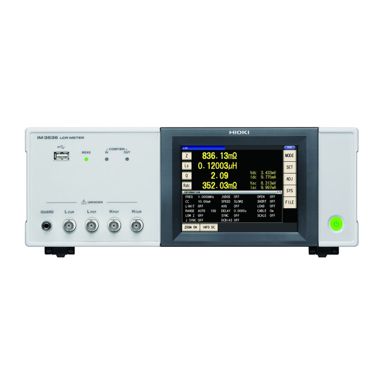
Page 24: Names And Functions Of Parts
Names and Functions of Parts 1.2 Names and Functions of Parts Front LCD display Measurement LEDs Judgment result This is a touch panel display. Lights during measurement. indication LEDs Press the keys displayed on the Indicates the judgment results screen to operate the instrument. for comparator and BIN mea- surement (p. - Page 25 Names and Functions of Parts Rear EXT I/O connector LAN connector Allows you to control the start of measurement and capture Allows you to connect the instrument to external judgment results by connecting a PLC or I/O board.(p. 162) devices using a LAN cable. (Bundled LCR Application Disc - Communications See “Before Connecting EXT I/O”...
-
Page 26: Screen Layout And Operation
Screen Layout and Operation 1.3 Screen Layout and Operation This instrument allows you to use a touch panel to set and change all measurement conditions. Gently touch a key on the screen to select the item or numerical value set for that key. A selected key turns black. - Page 27 Screen Layout and Operation LCR mode This screen is used to select the mea- surement mode (p. 24). MODE screen Measurement screen This screen is used to configure detailed This screen is used to view measured values and measurement condition set- settings such as tings information.
-
Page 28: X84; Viewing Measured Values (Measurement Screen)
Screen Layout and Operation Viewing measured values (Measurement screen) This is the first screen displayed when the instrument is turned on. Touch the EXIT key to return to the measurement screen from another screen. Displaying elements used in both LCR mode and continuous measurement mode Indicates the usage status of internal memory (p. - Page 29 Screen Layout and Operation Measurement screen in LCR mode Indicates the name of the Measured values* loaded panel (p. 128). Displays measured values for various parameters. Parameter keys Monitor values Sets which param- Vac, Vdc: Voltage between the eters to display on sample terminals the measurement Iac, Idc: Current passing through...
-
Page 30: X84; Select The Measurement Mode (Mode Screen)
Screen Layout and Operation Select the measurement mode (MODE screen) This screen is used to select the measurement mode. Touch the MODE key. Select the measurement mode. Displays the measurement screen for the selected mode. LCR mode (p. 39) CONTINUOUS Continuous measurement mode (p. -
Page 31: X84; Setting Detailed Settings Such As Measurement Conditions (Set Screen)
Screen Layout and Operation Setting detailed settings such as measurement conditions (SET screen) This screen is for configuring the measurement conditions you want to change and other advanced settings. Select the measurement mode (p. 24) before configuring the advanced settings. (Example screen: LCR mode) For more information about the continuous measurement (CONTINUOUS) mode screen, see “4 Using Continuous Measurement Mode”... -
Page 32: X84; Checking Measurement Condition Settings Information
Screen Layout and Operation Checking measurement condition settings information You can check settings information on the Mea- surement screen during LCR mode operation. Current measurement conditions (This information is not shown when using the zoom display (p. 42)). Touching the INFO key switches the dis- INFO AC... -
Page 33: X84; Configuring Correction Functionality (Adj Screen)
Screen Layout and Operation The following information can be displayed: Display Description Remarks FREQ Measurement frequency RANGE Measurement range LOW Z Low Z high accuracy mode For AC and DC JUDGE synchronization setting for the J SYNC measurement range SPEED Measurement speed Average AC: Setting... -
Page 34: X84; Configuring The Instrument's Interfaces, Setting The Time And Date, And Checking The System (Sys Screen)
Screen Layout and Operation Configuring the instrument’s interfaces, setting the time and date, and checking the system (SYS screen) This screen is used to configure the instrument’s interfaces, to set the time and date, and to check the system. (LCR mode only) Touch the key. -
Page 35: X84; Displaying And Manipulating Files On The Usb Flash Drive (File Screen)
Screen Layout and Operation Displaying and manipulating files on the USB flash drive (FILE screen) This screen is used to display files saved on the USB flash drive and to configure and edit file-relat- ed settings. It is displayed after the USB flash drive is inserted into the instrument’s receptacle. Touch the FILE key. - Page 36 Screen Layout and Operation...
-
Page 37: Measurement Preparations
Refer to “Appx. 9 Attaching Rack-mounting Hardware to the Instrument” (p. Appx.12) for rack mount- ing. (1) Installing the Instrument (p. 12) (2) Connecting the Power Cord (p. 34) (3) Connect measurement cables, optional Hioki probes or test fixture to the measurement connectors (p. 35) Check that the instrument’s power switch is turned off. - Page 38 Preparation Flowchart (6) Make instrument settings • First, set the time and date (p. 38). • When measuring DC resistance, be sure to set the line frequency before performing measurement (p. 53). After allowing the instrument to warm up for at least 60 minutes, perform open correction and short correction and connect the instrument to the sample (p.
-
Page 39: Pre-Operation Inspection
Please read the “Operating Precautions” (p. 12) before use. Before using the instrument, verify that it operates normally to ensure that no damage occurred during storage or shipping. If you find any damage, contact your authorized Hioki distributor or reseller. -
Page 40: Connecting The Power Cord
Connecting the Power Cord 2.3 Connecting the Power Cord Be sure to read the “Before Turning Power On” (p. 13), and “Handling the cords, fixtures, and probes” (p. 14) before connecting the power cord. Connect the power cord to the power inlet on the instrument, and plug it into an outlet. Check that the instrument’s power is turned off. -
Page 41: Connecting The Measurement Cables, Probes, Or Fixture
(Ensure that a shield is not connected to a core wire.) • In general, Hioki optional parts (p. 2) should be used for measurement cables and fixtures. If you use a probe yourself, it may not be able to satisfy the specifications of this instrument. -
Page 42: Turning The Power On And Off
Before turning on the instrument, be sure to read “Before Turning Power On” (p. 13). Once you have connected measurement cables or an optional Hioki probe or test fixture, turn on the instrument’s main power switch. Once the main power switch has been turned on, the instru- ment can be turned on and off using the power button on the front panel. - Page 43 Turning the Power On and Off Turning main power on Placing the instrument in the suspended state Place the main power switch in the “on” (I). ON the main power in the state, hold down the front Standby Key 2 seconds approxi- mately.
-
Page 44: Setting The Date And Time
Setting the Date and Time 2.6 Setting the Date and Time Set the instrument’s date and time. Data is recorded and managed based on the set date and time. Press the key. Press the key to accept the setting. CLOCK Touch the tab, and set the date Press the... -
Page 45: Performing Measurements In Lcr Mode
Setting Display Parameters Performing Measurements in LCR Mode The LCR mode allows you to measure the impedance, phase angle, and other items by applying any frequency or level (effective value) signal to the element you want to measure. This function is suitable for evaluating the passive element of a capacitor, coil, or the like. -
Page 46: X84; To Perform Dc Measurement (Dc Resistance Measurement)
Setting Display Parameters Parameters The following parameters are available: Parameters Description Parameters Description Capacitance (F) Ω Impedance ( (Equivalent series capacitance) Capacitance (F) Admittance (S) (Equivalent parallel capacitance) θ Impedance phase angle (°) Q-factor Ω Effective resistance= ESR ( Loss factor= tanδ (Equivalent series resistance) Ω... -
Page 47: Viewing Measured Values
Viewing Measured Values 3.2 Viewing Measured Values Measured values for each parameter are shown next to the corresponding parameter key. The measured values shown in the screenshot below are as follows: Ω : 4.93874 k No. 1 parameter Z (impedance) No. -
Page 48: Enlarging Display Of Measurement Values
Enlarging Display of Measurement Values 3.3 Enlarging Display of Measurement Values The measurement values and comparator judgment results can be displayed in enlarged form. This functionality provides a convenient way to make measured values easier to view. Touch the ZOOM ON key. -
Page 49: Setting Measurement Conditions (Basic Settings)
Setting Measurement Conditions (basic settings) 3.4 Setting Measurement Conditions (basic set- tings) (There are two types of measurement: AC measurement and DC measurement (p. 4 0). The measurement conditions set for AC measurement and DC measurement differ. Required: Be sure to set. Optional: Change setting as necessary. -
Page 50: X84; Required Settings
Setting Measurement Conditions (basic settings) Refer to the “AC,” “DC,” “AC/DC,” and “Common” notation next to settings. (AC) Set when performing AC measurement. (DC) Set when performing DC measurement. • Set when performing AC or DC measurement. Set on the BASIC tab screen for AC measurement and on the [Rdc] tab screen for DC measurement. - Page 51 Setting Measurement Conditions (basic settings) Measurement range (AC/DC) There are the following three methods for setting the measurement range. The most suitable test range is set automatically. AUTO (p. 4 6) (This setting is useful when measuring a sample whose impedance varies great- ly with measurement frequency or when measuring an unknown sample.) The measurement range is fixed.
- Page 52 Setting Measurement Conditions (basic settings) Setting AUTO ranging Screen display method (For more information, see p. 2 4.): AC measurement: (Measurement screen) SET key>(SET screen) BASIC tab>RANGE DC measurement: (Measurement screen) SET key>(SET screen) Rdc tab>RANGE Touch the AUTO key. Touch the EXIT key twice.
- Page 53 Setting Measurement Conditions (basic settings) Setting the ranging to HOLD Screen display method (For more information, see p. 2 4.): AC measurement: (Measurement screen) SET key>(SET screen) BASIC tab>RANGE DC measurement: (Measurement screen) SET key>(SET screen) Rdc tab>RANGE Touch the HOLD key and then select the Touch the...
- Page 54 Setting Measurement Conditions (basic settings) Judgment synchronization setting When the JUDGE SYNC setting is turned on, the instrument will select the optimal range automati- cally based on the comparator measurement or BIN measurement judgment standard. (See "Judg- ing Measurement Results" (p. 6 8).) This setting is useful when performing comparator measurement or BIN measurement of a variety of impedance samples, including samples whose impedance varies greatly with frequency.
- Page 55 Setting Measurement Conditions (basic settings) Measurement signal level (AC) Sets the measurement signal level to apply to the sample. The measurement signal level applied to the sample can be set using the following three modes: (See "About the measurement signal mode" (p. 5 2).) Open circuit voltage (V) mode The value of the open circuit voltage is set.
- Page 56 Setting Measurement Conditions (basic settings) For setting range and accuracy Open circuit voltage (V) mode and Constant voltage (CV) mode setting When low-Z high-precision mode Normal operation (p. 5 5) is on 0.010 V to 5.000 V 0.010 V to 1.000 V Open circuit voltage setting range 1 MHz or less: ±10% rdg.
- Page 57 Setting Measurement Conditions (basic settings) Constant current (CC) mode setting Low Z high accuracy mode Low Z high accuracy mode (p. 5 5) is set to OFF (p. 5 5) is set to ON 0.01 mA to 50.00 mA 0.01 mA to 100.00 mA Constant current setting range ±1%±10 µA Constant current accuracy...
- Page 58 Setting Measurement Conditions (basic settings) About the measurement signal mode Relationship between the measurement signal mode of the instrument and the sample is as follows. Open circuit voltage (V) mode This voltage value is the value which is applied across the two terminals of the series combination of the object which is being tested and the output impedance.
- Page 59 Setting Measurement Conditions (basic settings) Line frequency (DC) When performing DC measurement, be sure to set the line frequency of the power supply being used. Screen display method (For more information, see p. 2 4.): (Measurement screen) SET key>(SET screen) Rdc tab>LINE FREQ Select the line frequency.
-
Page 60: X84; User-Configurable Settings
Setting Measurement Conditions (basic settings) User-configurable settings Measurement speed (AC/DC) The measurement speed can be set. The slower the measurement speed is, the more accurate are the results. Screen display method (For more information, see p. 2 4.): AC measurement (Measurement screen) SET key>(SET screen) BASIC tab>SPEED... - Page 61 Setting Measurement Conditions (basic settings) Low Z High Accuracy Mode (high-precision measurement) (AC/DC) Ω Enabling low-Z high-precision mode will switch the output resistance to 10 , enabling high-preci- sion measurement by allowing an adequate amount of current to flow to the measurement sample. Screen display method (For more information, see p. ...
- Page 62 Setting Measurement Conditions (basic settings) Averaging (limiting display value instability) (AC/DC) With the averaging function, the measured values can be averaged. This function can be used to limit instability of displayed measured values. AC measurement A rolling average of the tested values over the set number of times for averaging is always calculated backwards from the present.
- Page 63 Setting Measurement Conditions (basic settings) Example: If the number of averaging iterations is set to 4 (measurement count, measured value output points, and method for calculating measured values at output) (1) Moving average Measurement points M1+M2 M1+M2+M3 M1+M2+M3+M4 Measurement value output M5+M6+M7+M8 M4+M5+M6+M7 M3+M4+M5+M6...
- Page 64 Setting Measurement Conditions (basic settings) Limit (limiting the voltage and current applied to the sample) (AC) Depending on the measurement signal level, in some cases it is possible to damage the sample which is being measured by applying to it a voltage or a current greater than its rated value. (See"Constant voltage (CV) mode"...
- Page 65 Setting Measurement Conditions (basic settings) When the limit function is ON, you may encounter a display such as the following. (Example: When constant voltage (CV) setting) ERR: If the voltage or current which is applied to LMT: When a lower signal level than the setting is being applied to the sample due to the voltage the sample under test exceeds the limit value (the current exceeding the limit value flows through...
- Page 66 Setting Measurement Conditions (basic settings) DC adjustment (reducing measurement error) (DC) Enabling the DC adjustment function causes the instrument to set the generated voltage to 0 V and acquire the offset value generated by its internal circuitry in order to reduce measurement error. (Default setting: ON) Disabling the DC adjustment function allows high-speed DC resistance measurement since the offset value is not acquired before each measurement is performed.
- Page 67 Setting Measurement Conditions (basic settings) • Measurement is switched between 1 V and 0 V to acquire the offset value. Set the DC delay (p. 6 1) and adjustment delay (p. 6 2) so that the measurement sample's inductance does not affect measured val- ues.
- Page 68 Setting Measurement Conditions (basic settings) Adjustment delay (setting the offset measurement delay time) (DC) This delay time serves to delay measurement until offset measurement (0 V DC) stabilizes. For more information about adjustment delay timing, see the figures in "Measurement and data acquisition timing"...
- Page 69 Setting Measurement Conditions (basic settings) External trigger input method There are the following three types of input method for a trigger. • Touching the TRIG key on the screen to manually apply the trigger causes the instrument to perform one measurement.
- Page 70 Setting Measurement Conditions (basic settings) Trigger synchronous output (Applying the signal to the sample during measure- ment only) (Common) After outputting the measurement signal at trigger input, applies the signal to the sample during measurement only. You can also set a delay time (Trigger synchronous delay) to ensure that data is acquired after the sample stabilizes.
-
Page 71: X84; Measurement And Data Acquisition Timing
Setting Measurement Conditions (basic settings) Measurement and data acquisition timing Measurement and data acquisition timing varies with the following settings: Trigger synchronous output (p. 6 4), Trigger delay (p. 6 3), Trigger synchronous delay (p. 6 4), DC delay (p. 6 1), Adjustment delay (p. 6 2) When the trigger synchronization function is on Trigger signal... - Page 72 Setting Measurement Conditions (basic settings) When the trigger synchronization function is off Trigger signal Trigger delay Data acquisition AC measurement (trigger synchronization off) Adjustment Switching time Trigger delay delay 1.5 ms DC measurement Data delay (trigger synchronization off) acquisition Data (DC adjustment on) acquisition Data...
-
Page 73: Permittivity
Setting Measurement Conditions (basic settings) When measuring conductivity and permittivity (permittivity) (p. 3 9) and set the conditions used to σ ε Set the parameters to (conductivity) and calculate conductivity and permittivity. Conductivity Value indicating the ease with which electricity is conducted by a substance Value indicating the ease with which an electric field can be formed in a sub- Permittivity stance (dielectric material) -
Page 74: Judging Measurement Results
Judging Measurement Results 3.5 Judging Measurement Results The measurement results are compared to an arbitrarily set reference and then the judgment re- sults are displayed. This function is useful for quality evaluation and the like. There is comparator measurement which compares one judgment reference and the measurement values, and BIN measurement which compares multiple judgment reference values (up to 10) and the measurement values. -
Page 75: X84; Setting The Judgment Mode
Judging Measurement Results Setting the judgment mode Select a judgment mode as described below and configure the settings. Screen display method (For more information, see p. 2 4): (Measurement screen) SET key>(SET screen) ADVANCED tab>JUDGE Select the judgment mode. Disables comparator and BIN func- tion. - Page 76 Judging Measurement Results The comparator decision mode can be set as one of the following: Absolute value (ABS) setting (p. 7 1) Set absolute values for the upper limit and lower limit Upper limit value values of the measurement parameters. The measurement values displayed are the same as those of the measurement parameters.
- Page 77 Judging Measurement Results Absolute value setting Set the value after setting the judgment mode (p. 6 9) to COMP. This explanation uses the example of setting the measurement conditions for the No. 1 parameter. Touch the key on the measurement Touch the key, and set the upper limit screen.
- Page 78 Judging Measurement Results Percentage setting and deviation percentage setting Set the value after setting the judgment mode (p. 6 9) to COMP. This explanation uses the example of setting the measurement conditions for the No. 1 parameter. Touch the key on the measurement Touch the key, and set the upper limit screen.
- Page 79 Judging Measurement Results Percentage setting • The actual operation performed internally is to calculate the upper limit comparison value (or lower limit comparison value) using the following formula and then compare it to the measured value to make a judg- ment.
-
Page 80: Multiple Judgment Standards)
Judging Measurement Results Configuring BIN function settings (judging measured values based on multiple judgment standards) Set the upper and lower limit values for two parameters and display up to 10 classifications of judg- ment results. You can also output the judgment results to an external device. (Measurement screen) (Judgment result indication LEDs) When the measurement result... - Page 81 Judging Measurement Results The BIN decision mode can be set as one of the following: Absolute value (ABS) setting (p. 7 6) Set absolute values for the upper limit and lower limit val- Upper limit value ues of the measurement parameters. The measurement values displayed are the same as those of the measurement parameters.
- Page 82 Judging Measurement Results Absolute value setting Set the value after setting the judgment mode (p. 6 9) to BIN. Touch the key on the measurement Touch the key for the No. 1 param- screen. eter. No. 1 parameter No. 3 parameter Touch the key.
- Page 83 Judging Measurement Results Percentage setting and deviation percentage setting Set the value after setting the judgment mode (p. 6 9) to BIN. key to confirm the ref- Touch the key on the measurement Touch the ENTER screen. erence value. Touch the EXIT key.
- Page 84 Judging Measurement Results Enter the upper limit value with the nu- meric keypad. Settable range -999.999% to 999.999% When you do not want to set the upper and lower limit values, touch the key. key to confirm the up- Touch the ENTER per limit value.
-
Page 85: Setting Application Settings
Setting Application Settings 3.6 Setting Application Settings Range synchronization (Setting measurement conditions for individu- al measurement Ranges) This section describes how to set measurement conditions for individual measurement ranges. Allows you to set the following measurement conditions for individual measurement ranges: •... - Page 86 Setting Application Settings (2) Setting measurement conditions on individual dialog boxes Screen display method (For more information, see p. 2 4): AC measurement: (SET screen) BASIC tab>LIST DC measurement: (SET screen) Rdc tab>LIST Select the measurement range you wish Set the conditions and touch the to configure with the ...
- Page 87 Setting Application Settings (3) Setting measurement conditions on a single screen Screen display method (For more information, see p. 2 4): AC measurement: (SET screen) BASIC tab>LIST DCmeasurement: (SETscreen) Rdc tab>LIST Select the measurement range you wish Touch the key to accept the set- to configure with ...
-
Page 88: Measurement Speed)
Setting Application Settings Waveform averaging function (increasing measurement precision or measurement speed) The number of measurement waveforms for each frequency band is set for the measurement speed settings (FAST, MED, SLOW, SLOW2), and this function allows you to set the number of measurement waveforms for each frequency band. - Page 89 Setting Application Settings Frequency band Settable range DC (Line frequency 50 Hz) 1 to 2000 DC measurement waveform count DC (Line frequency 60 Hz) 1 to 2400 performs waveform averaging us- ing 1/100 of the set line frequency 4.00 Hz to 10.00 Hz 1 to 4 as one wave.
-
Page 90: X84; High-Z Reject Function (Detecting Contact Errors During 2-Terminal Measurement)
Setting Application Settings High-Z reject function (detecting contact errors during 2-terminal mea- surement) This functionality outputs an error when the measurement results exceed a set judgment standard, allowing poor contact to be detected when using a 2-terminal fixture to perform measurement. Er- rors are shown on the measurement screen and output to EXT I/O. -
Page 91: (Detecting Poor Contact With The Sample During 4-Terminal Measurement)
Setting Application Settings Contact check function (detecting poor contact with the sample dur- ing 4-terminal measurement) This functionality allows you to detect contact defects between the terminals (H , and ) and the sample during 4-terminal measurement. Set the contact resistance between L and L and between H and H... -
Page 92: (Saving Measurement Results)
Setting Application Settings Memory function (saving measurement results) You can save the measurement results inside the instrument (Up to 32,000 items).This function al- lows you to save previously saved measurement results to the USB flash drive and to acquire them from a computer using the :MEMory? communications command. -
Page 93: X84; Number Of Effective Digits Of The Measurement Value
Setting Application Settings • If the memory function is enabled or IN), the number of memory items currently saved is displayed in the measurement screen. Indicates that the number of memory items currently saved is 2,929. • Save the data stored in the instrument to a USB flash drive or acquire it with the :MEMory? command. -
Page 94: X84; Lcd Display Auto-Off (Power-Saving Mode)
Setting Application Settings LCD display auto-off (power-saving mode) You can set whether the LCD display remains on continuously or turns off automatically. Setting the LCD display to causes the LCD display to automatically turn off after there is no panel use for 10 seconds, thereby reducing power consumption. -
Page 95: X84; Key Tones And Judgment Tones
Setting Application Settings Key tones and judgment tones You can set the operation sound and each of the beep sounds for judgment results. Screen display method (For more information, see p. 2 4): (Measurement screen) SET key>(SET screen) ADVANCED tab>BEEP Configure beep tones. -
Page 96: X84; Key-Lock Function (Disabling Key Operation)
Setting Application Settings Key-lock function (Disabling key operation) When the key-lock function is enabled, all setting changes except canceling the key-lock are dis- abled to protect the settings. You can also set a passcode (security code). Screen display method (For more information, see p. 2 4): (Measurement screen) SET key>(SET screen) - Page 97 Setting Application Settings Disabling the Key-lock Touch the UNLOCK key when the key- If the error indication shown below, check lock is enabled. the following items. (When a passcode is set) Cause Remedy Enter the passcode and touch the UNLOCK Touch the key and was touched before...
- Page 98 Setting Application Settings...
-
Page 99: Using Continuous Measurement Mode
Setting Which Panels to Use in Continuous Measurement Using Continuous Measurement Mode In continuous measurement mode, a series of measurement conditions saved using the panel save function (p. 124) are loaded in order, and measurement is performed continuously using multiple different sets of conditions. -
Page 100: Performing Continuous Measurement
Performing Continuous Measurement 4.2 Performing Continuous Measurement Perform continuous measurement. On the measurement screen, a list of the To cancel continuous measurement, touch panels selected for use in continuous mea- STOP key. surement will be shown on the screen (BASIC tab). -
Page 101: Changing The Display Timing Setting (When You Wish To Shorten The Screen Update Interval)
Changing the Display Timing Setting (When You Wish to Shorten the Screen Update Interval) 4.4 Changing the Display Timing Setting (When You Wish to Shorten the Screen Update Interval) You can set the display timing during continuous measurement as desired. If the display timing is set to REAL, the time for continuous measurement becomes long because the screen is updated every time measurement is performed. -
Page 102: Setting The Lcd Display Auto-Off (When You Wish To Save The Power)
Setting the LCD display auto-off (When You Wish to save the power) 4.5 Setting the LCD display auto-off (When You Wish to save the power) You can set whether the LCD display remains on continuously or turns off automatically. Setting the LCD display to causes the LCD display to automatically turn off after there is no panel use for 10 seconds, thereby reducing power consumption. -
Page 103: Error Correction
Error Correction Measurement cables, probes, and fixtures have stray admittance and residual impedance. Since these characteristics influence measured values, measurement accuracy can be increased by cor- recting for them. First, set the measurement mode to LCR mode (p. 24). Settings are configured on the screen. -
Page 104: Setting The Cable Length (Cable Length Correction)
Setting the Cable Length (Cable Length Correction) 5.1 Setting the Cable Length (Cable Length Correc- tion) With high frequency measurement, the influence of the cable results in large measurement errors. Setting the cable length enables you to reduce the measurement errors. Use a coaxial cable with Ω... -
Page 105: Open Correction
For more information about how to connect the instrument, see "2.4 Connecting the Measurement Cables, Probes, or Fixture" (p. 35). Adjust the distance between the HI and LO terminals of the measurement cable or Hioki op- tional probe or fixture to the width of the measurement sample and place them in the open... -
Page 106: X84; All Correction
Open Correction All correction Simultaneously acquire the open correction values for all measurement frequencies. Screen display method (For more information, see p. 27): (Measurement screen) ADJ key>(ADJ screen) OPEN Correction will start. Touch the ADJUST key. Correction value acquisition time: Approx. - Page 107 Open Correction Correction range limitation function (to shorten the correction time) In All correction, correction is performed for the entire frequency range. By setting the minimum and maximum correction frequencies with this function, you can reduce the time required to perform the correction process.
- Page 108 Open Correction Touch the key. The display will return from the ADJ>OPEN screen. • If the maximum correction frequency is less than the minimum correction frequency, the maximum and minimum correction frequen- cies will be switched automatically. • If the default settings are being used, the instru- MINIMUM and MAXIMUM.
-
Page 109: X84; Spot Correction
Open Correction Spot correction Acquire the correction values at the set measurement frequencies. Measurement frequencies can be set for up to five points. Screen display method (For more information, see p. 27): (Measurement screen) ADJ key>(ADJ screen) OPEN Enter the frequency to correct with the Touch the ADJUST key. - Page 110 Open Correction The next screen will be displayed once cor- Touch the EXEC key. rection has completed normally. If correction has never been performed, the correction values become 0. Correction results (Conductance, susceptance) Touch when you wish to cancel correction. (The display will return to the screen shown Measurement frequency Correction...
-
Page 111: Short Correction
Short Correction 5.3 Short Correction With short correction, it is possible to reduce the influence of the residual impedance of the mea- surement cables and thereby to enhance the accuracy of measurement. It is effective for measurement samples whose impedance is relatively low. There are the following three methods for setting the open correction. -
Page 112: X84; All Correction
Short Correction All correction Simultaneously acquire the short correction values for all measurement frequencies. Screen display method (For more information, see p. 27): (Measurement screen) ADJ key>(ADJ screen) SHORT Correction starts. Touch the ADJUST key. Compensation value acquisition time: Approx. 50 seconds Touch the key, and then touch the EXIT... -
Page 113: X84; Spot Correction
Short Correction Spot correction Acquire the correction values at the set measurement frequencies. Measurement frequencies can be set for up to five points. Screen display method (For more information, see p. 27): (Measurement screen) ADJ key>(ADJ screen) SHORT Enter a frequency for correction, and Touch the ADJUST key. - Page 114 Short Correction The next screen will be displayed once cor- Touch the EXEC key. rection has completed normally. If correction has never been performed, the correction values become 0. Correction results (Effective resistance, reactance) Touch when you wish to cancel correction. (The display will return to the screen shown Measurement frequency Correction...
-
Page 115: If Open Or Short Correction Fails To Complete Normally
If Open or Short Correction Fails to Complete Normally 5.4 If Open or Short Correction Fails to Complete Normally A window such as the following will be displayed. (1) If the instrument was unable to acquire a compensation value for the optimal range due to the effects of noise A window such as the following will be displayed. - Page 116 If Open or Short Correction Fails to Complete Normally Solution Both open correction and short correction • Check the correction status of the measurement cables (probe and fixture) (p. 2). • Check the cable length correction setting. (If the setting is incorrect, it may not be possible to perform correction at high frequencies.) •...
-
Page 117: Disabling Open And Short Correction Values
Disabling Open and Short Correction Values 5.5 Disabling Open and Short Correction Values Turning off the correction setting will disable the correction values you have acquired. Screen display method (For more information, see p. 27): To disable open correction: (Measurement screen) ADJ key>(ADJ screen) OPEN... -
Page 118: Load Correction (Correcting Values To Match Reference Values)
Load Correction (Correcting Values to Match Reference Values) 5.6 Load Correction (Correcting Values to Match Reference Values) This section describes how to correct measured values based on a reference sample. A sample with a known measured value is measured. Then a correction coefficient is calculated and used to correct future measured values. -
Page 119: X84; Procedures For The Load Correction
Load Correction (Correcting Values to Match Reference Values) Procedures for the load correction Once you have set the measurement cable length, use the following procedure to configure the load correction conditions and perform correction. (See "5.1 Setting the Cable Length (Cable Length Correction)" (p. 98).) Screen display method (For more information, see p. - Page 120 Load Correction (Correcting Values to Match Reference Values) Correction starts. The instrument will return to the Correction value acquisition time varies screen. with the measurement frequency and num- If correction does not complete normally: ber of points. (p. 119) Touch the EXIT key.
- Page 121 Load Correction (Correcting Values to Match Reference Values) Setting the correction frequency Enter the correction frequency with the Touch the FREQ key. numeric keypad, and touch the unit key to confirm the setting. Touch when you Touch when you wish to cancel input.
- Page 122 Load Correction (Correcting Values to Match Reference Values) Setting the measurement signal mode and level value for the correction signal level Touch the LEVEL key. Enter the voltage level or current level with the keys. Select the correction signal level measure- For settable range, see the following table.
- Page 123 Load Correction (Correcting Values to Match Reference Values) Setting the DC bias Settable range: 0 V to 2.5 V Touch the DC BIAS key. If you make a mistake, touch the key to reenter the value. Touch the EXIT key. The dialog box will be closed.
- Page 124 Load Correction (Correcting Values to Match Reference Values) Setting reference values Enter the reference value for the parameter displayed to the left of the parameter mode for REF1 and the reference value for the parameter displayed to the right of the parameter mode for REF2. Touch the REF1 key.
-
Page 125: X84; To Reset The Correction Condition Settings
Load Correction (Correcting Values to Match Reference Values) To reset the correction condition settings This section describes how to clear all settings for the selected correction condition number. Screen display method (For more information, see p. 27): (Measurement screen) ADJ key>(ADJ screen) LOAD Select the correction condition number... -
Page 126: X84; Disabling Load Correction
Load Correction (Correcting Values to Match Reference Values) Disabling load correction You can disable correction by setting the correction setting to OFF. Screen display method (For more information, see p. 27): (Measurement screen) ADJ key>(ADJ screen) LOAD Touch the ADJUST key. -
Page 127: Correcting Measured Values With A User-Specified Correction Coefficient (Correlation Correction)
Correcting Measured Values with a User-specified Correction Coefficient (Correlation Correction) 5.7 Correcting Measured Values with a User-specified Correction Coefficient (Correlation Correction) This functionality enables you to correct measured values using a user-specified correction coef- ficient. This function can be used to provide compatibility among measurement devices. Set the correction coefficients A and B for the measurement values of No. - Page 128 Correcting Measured Values with a User-specified Correction Coefficient (Correlation Correction) Touch the key. Touch the key. Enter the correction coefficient with the numeric keypad, and touch the key to accept the value. Touch the EXIT key. Displays the measurement screen. Step the units up.
-
Page 129: Saving And Loading Measurement Condition And Correction Value Data
The instrument contains a built-in backup lithium battery which offers a service life of about ten years. • When the life of the built-in lithium battery ends, the measurement conditions will no longer be able to be saved. Contact your authorized Hioki distributor or reseller. -
Page 130: Saving Measurement Conditions And Correction Values (Panel Save Function)
Saving Measurement Conditions and Correction Values (Panel Save Function) 6.1 Saving Measurement Conditions and Correction Values (Panel Save Function) This section describes how to save measurement condition data and correction value data in the instrument’s memory. The following number of data sets can be saved: (Measurement condition: Up to 60 items, Correction value: Up to 128 items) First, select the data type you wish to save. - Page 131 Saving Measurement Conditions and Correction Values (Panel Save Function) PANEL screen layout Number of data sets saved The text color changes in accordance with the number of data items currently saved as shown in the table below. Text colors: White Yellow 0 to 29 30 to 59...
- Page 132 Saving Measurement Conditions and Correction Values (Panel Save Function) Saving measurement conditions and correction values Screen display method (For more information, see p. 24.) (Measurement screen) SET key>(SET screen) ADVANCED tab>PANEL Select the panel number to save with Enter the panel name with the numeric ...
- Page 133 Saving Measurement Conditions and Correction Values (Panel Save Function) (To overwrite an existing panel) OVER WRITE dialog box will be displayed. Touch the OVER WRITE key. Touch when you wish to cancel the save (overwrite) operation. Touch the EXIT key twice. Displays the measurement screen.
-
Page 134: Loading Measurement Conditions And Correction Values (Panel Load Function)
Loading Measurement Conditions and Correction Values (Panel Load Function) 6.2 Loading Measurement Conditions and Correc- tion Values (Panel Load Function) This section describes how to load panel data that has been saved in the instrument’s memory. The instrument’s settings will be replaced with the loaded data settings. Screen display method (For more information, see p. -
Page 135: Changing A Panel Name
Changing a Panel Name 6.3 Changing a Panel Name This section describes how to change the name of a panel saved in the instrument’s memory. Screen display method (For more information, see p. 24.) (Measurement screen) SET key>(SET screen) ADVANCED tab>PANEL Select the panel number whose name Enter a panel name with the numeric ... -
Page 136: Deleting A Panel
Deleting a Panel 6.4 Deleting a Panel This section describes how to delete a panel that has been saved in the instrument’s memory. Screen display method (For more information, see p. 24.) (Measurement screen) SET key>(SET screen) ADVANCED tab>PANEL Select the panel number you wish to (You will be able to check some of the con- ... -
Page 137: Setting The System
Setting the System This chapter describes how to configure the instrument’s system settings. First, set the measurement mode to LCR mode (p. 24). Settings are configured on the screen. Allows you to configure settings used to control the instrument Configuring interface settings from a computer via its USB, GP-IB, RS-232C, or LAN inter- (p. -
Page 138: Setting The Interface (Controlling The Instrument From A Computer)
Setting the Interface (Controlling the Instrument from a Computer) 7.1 Setting the Interface (Controlling the Instrument from a Computer) This section describes how to configure the settings that are used to control the instrument via its USB, GP-IB, RS-232C, or LAN interface. Screen display method (For more information, see p. -
Page 139: Testing The System (Self Diagnosis)
If there is still problem after performing panel If the pressed keys are highlighted and the calibration, the panel may be malfunctioning. Contact your authorized Hioki distributor or green appears, the touch panel is work- reseller. ing properly. -
Page 140: X84; Panel Calibration
Touch when you wish to repeat panel correc- tion from the beginning. If the key does not appear, the instru- ment needs to be repaired. Contact your authorized Hioki distributor or reseller. Touch the key. EXIT Displays the measurement screen. -
Page 141: X84; Rom/Ram Test
No operation is possible during the ROM/ If the overall judgment result indication is NG, RAM test. the instrument needs to be repaired. Contact your authorized Hioki distributor or reseller. Never turn off the power during a test. Touch the key twice. - Page 142 Testing the System (Self diagnosis)
-
Page 143: Using Usb Flash Drive (Saving And Loading Data)
Using USB Flash Drive (Saving and Loading Data) Before using this functionality, be sure to read "Before Using the USB Flash Drive" (p. 14). This section describes how to save measurement data, instrument settings, and other data on a USB flash drive as well as how to load data that has been saved on a USB flash drive. Checking the Contents of Allows you to check the contents of files saved on a USB flash drive. -
Page 144: Inserting And Removing A Usb Flash Drive
Inserting and Removing a USB flash drive 8.1 Inserting and Removing a USB flash drive Inserting a USB flash drive Insert the USB flash drive into the USB receptacle on the front of the instrument. • Do not insert a USB flash drive that is not Mass Storage Class compatible. •... -
Page 145: Checking The Contents Of Files On A Usb Flash Drive
Checking the Contents of Files on a USB flash drive 8.2 Checking the Contents of Files on a USB flash drive This section describes how to display files and check their contents. Screen display method (For more information, see p. 29.): (Measurement screen) FILE key>(FILE screen) -
Page 146: Formatting A Usb Flash Drive
Formatting a USB Flash Drive 8.3 Formatting a USB Flash Drive The USB flash drive must be formatted (initialized) before it can be used. The instrument formats drives in the FAT32 format. Formatting is necessary since files on the USB flash drive can only be recognized when stored using the FAT32 file system. -
Page 147: Saving Measurement Data
Saving Measurement Data 8.4 Saving Measurement Data Saving Measurement Data in text can be saved to a USB flash drive in the CSV format. (*: Refers to one piece of Measurement data data measured before the SAVE key is touched. To save all measurement data stored in the instru- ment’s memory, see "Memory function (saving measurement results)"... - Page 148 Example of saving DATE (save date and time): ON, SET (measurement conditions) ON, PARA (measurement parameters): ON, DELIM (delimiter): , (comma), QUOTE (quotaion mark) " (double quotation) ”,” Quotation mark Delimiter "HIOKI E.E. CORPORATION","IM3536","Ver. 1.00", Instrument "Serial No. 123456789" information "DATE","11-11-30" "TIME","10:10:06" Time and date "FREQ","1.0000E+03","Hz"...
- Page 149 Saving Measurement Data Procedures Screen display method (For more information, see p. 29.): (Measurement screen) FILE key>(FILE screen) Insert the USB flash drive into the front Set the header, delimiter, and quotation USB connector (p. 138). mark character. Touch the TYPE key.
- Page 150 EXIT key. header) or the key (do not save as The dialog box will be closed. the header). When ON When OFF "HIOKI E.E. CORPORATION","IM3536","Ver. 1.00", "HIOKI E.E. CORPORATION","IM3536","Ver. 1.00", "Serial No. 123456789" "Serial No. 123456789" "DATE","11-11-30" "FREQ","1.0000E+03","Hz" "TIME","10:10:06" "V","1.000","V"...
- Page 151 EXIT key. header) or the key (do not save as The dialog box will be closed. the header). When ON When OFF "HIOKI E.E. CORPORATION","IM3536","Ver. 1.00", "HIOKI E.E. CORPORATION","IM3536","Ver. 1.00", "Serial No. 123456789" "Serial No. 123456789" "DATE","11-11-30" "DATE","11-11-30" "TIME","10:10:06" "TIME","10:10:06"...
- Page 152 EXIT key. header) or the key (do not save as The dialog box will be closed. the header). When ON When OFF "HIOKI E.E. CORPORATION","IM3536","Ver. 1.00", "HIOKI E.E. CORPORATION","IM3536","Ver. 1.00", "Serial No. 123456789" "Serial No. 123456789" "DATE","11-11-30" "DATE","11-11-30" "TIME","10:10:06" "TIME","10:10:06"...
- Page 153 Saving Measurement Data The following parameter symbols are used when saving text files: Symbol used when Parameters Description saving text files Ω Impedance ( Z [ohm] Admittance (S) Y [S] θ Impedance phase angle (°) PHASE [deg] Ω Effective resistance= ESR ( )(Equivalent series resistance) RS [ohm] Ω...
- Page 154 "MED" "TRIG","INT" "TRIG" "INT" "AVG","OFF" "AVG" "OFF" When semicolon When space "HIOKI E.E. CORPORATION";"IM3536";"Ver. 1.00"; "HIOKI E.E. CORPORATION" "IM3536" "Ver. 1.00" "Serial No. 123456789" "Serial No. 123456789" "DATE";"11-11-30" "DATE" "11-11-30" "TIME" "10:11:48" "TIME";"10:11:42" "FREQ";"1.0000E+03";"Hz" "FREQ" "1.0000E+03" "Hz" "V";"1.000";"V" "V" "1.000" "V"...
- Page 155 Sets the quotation mark to a single quotation mark ('). Touch the EXIT key. The dialog box will be closed. When double quotation mark When OFF HIOKI E.E. CORPORATION,IM3536,Ver. 1.00, "HIOKI E.E. CORPORATION","IM3536","Ver. 1.00", Serial No. 123456789 "Serial No. 123456789" DATE,11-11-30 "DATE","11-11-30" TIME,10:12:05 "TIME","10:10:06"...
-
Page 156: X84; Saving A Copy Of The Screen
Saving Measurement Data Saving a copy of the screen Allows you to save the screen currently displayed to the USB flash drive in bmp file format (256 colors or monochrome [2 colors]). The file extension is ".bmp". BMP file sample Color Monochrome... - Page 157 Saving Measurement Data Procedures Screen display method (For more information, see p. 29.): (Measurement screen) FILE key>(FILE screen) Insert the USB flash drive into the front Touch the EXIT key twice. Displays the measurement screen. USB connector (p. 138). Touch the TYPE key.
-
Page 158: X84; To Specify The Save Folder
Saving Measurement Data To specify the save folder This section describes how to set the desired folder as the data save destination. Screen display method (For more information, see p. 29.): (Measurement screen) FILE key>(FILE screen) Insert the USB flash drive into the front AUTO Automatically creates a folder USB connector (p. -
Page 159: Saving Settings Data
Saving Settings Data 8.5 Saving Settings Data Saving instrument settings other than panels This section describes how to save instrument settings other than panels on a USB flash drive. The extension of the setting file is “.SET.” This function is convenient for when you want to back up the setting state of the instrument. -
Page 160: Panels (All Save Function)
Saving Settings Data Save all instrument settings including panels (ALL SAVE function) This section describes how to save instrument settings including panels as settings files on the USB flash drive. The file extension will be “.ALL.” At this time, settings files (extension “.SET”) and panel files (extension “.PNL”) will also be saved separately in the same folder. -
Page 161: Loading Instrument Settings
Loading Instrument Settings 8.6 Loading Instrument Settings Loading settings files or panel files This section describes how to load a setting file (SET) or panel file (PNL) that is saved to the USB flash drive, and to restore the settings. Screen display method (For more information, see p. -
Page 162: Files (All Load Function)
Loading Instrument Settings Loading settings files including panel files (ALL LOAD function) This section describes how to load settings files (ALL) including panel files saved on the USB flash drive with the ALL SAVE function and restore the stored settings. Screen display method (For more information, see p. -
Page 163: Checking The Contents Of A File
Checking the Contents of a File 8.7 Checking the Contents of a File This section describes how to check measurement data files (CSV), screen copy files (BMP), set- tings files (SET), and panel save files (PNL) saved on a USB flash drive on the instrument’s screen. Screen display method (For more information, see p. -
Page 164: Deleting Files And Folders
Deleting Files and Folders 8.8 Deleting Files and Folders This section describes how to delete files and folders saved on a USB flash drive. Screen display method (For more information, see p. 29.): (Measurement screen) FILE key>(FILE screen) LIST Insert the USB flash drive into the front Touch the DELETE key. -
Page 165: Creating Folders
Creating Folders 8.9 Creating Folders This section describes how to create a folder on a USB flash drive. Screen display method (For more information, see p. 29.): (Measurement screen) FILE key>(FILE screen) LIST Insert the USB flash drive into the front USB connector (p. -
Page 166: Displaying The Usb Flash Drive Information
Displaying the USB Flash Drive Information 8.10 Displaying the USB Flash Drive Information Allows you to check the usage rate and file system of the USB flash drive. Screen display method (For more information, see p. 29.): (Measurement screen) FILE key>(FILE screen) LIST Insert the USB flash drive into the front... -
Page 167: External Control
External Control This chapter describes how to connect the EXT I/O connector on the rear of the instrument to an external device and how to control the instrument using the following methods: • Outputting signals from the instrument to the external device (measurement complete signal, judgment results signal, etc.) •... -
Page 168: External Input/Output Connector And Signals
External Input/Output Connector and Signals 9.1 External Input/Output Connector and Signals Before connecting the terminals, be sure to read "Before Connecting EXT I/O" (p. 15). This section describes the instrument’s EXT I/O connectors, compatible connectors, connector signal assignments, input (IN) signal functionality, and output signals when errors occur. Signal input or output is indicated as “LO (ON),”... - Page 169 External Input/Output Connector and Signals Signal name Function Logic ― ― ― ― TRIG External trigger Rising/ Edge (See "Input (IN) signal function details" (p. 167).) falling (Unused) (Unused) ― ― ― Select panel number Negative Level (See "Input (IN) signal function details" (p. 167).) ―...
- Page 170 External Input/Output Connector and Signals Signal name Function Logic ― ― ― Select panel number Negative Level (See "Input (IN) signal function details" (p. 167).) ― ― ― Select panel number Negative Level (See "Input (IN) signal function details" (p. 167).) ―...
- Page 171 External Input/Output Connector and Signals Continuous measurement mode (CONTINUOUS) operation Signal name Function Logic ― ― ― ― TRIG External trigger Rising/ Edge (See "Input (IN) signal function details" (p. 167).) falling (Unused) (Unused) (Unused) (Unused) (Unused) (Unused) ISO_5V Isolated 5 V power output ISO_COM Isolated common signal ground ―...
- Page 172 External Input/Output Connector and Signals Signal name Function Logic (Unused) (Unused) (Unused) (Unused) (Unused) (Unused) (Unused) (Unused) ISO_COM Isolated common signal ground ― ― ― This signal indicates that measurement is complete. “HI (OFF)” indicates that measurement is in progress, while “LO (ON)”...
-
Page 173: X84; Instrument Connector Signal Assignments 162 „ Input (In) Signal Function Details
External Input/Output Connector and Signals Input (IN) signal function details This section describes input (IN) signals. Input (IN) sig- Detailed description ― ― ― ― • When the trigger setting is the external trigger (EXT), measurement is performed once TRIG ―... -
Page 174: X84; Bcd Mode Function Details
External Input/Output Connector and Signals BCD mode function details LCD mode output signals operate in two modes: judgment mode and BCD mode. In BCD mode, measured values for the No. 1 parameter and the No. 3 parameter are output using the BCD sig- nals. - Page 175 External Input/Output Connector and Signals Example output The decimal point is set to an appropriate position. 12.3456 µF Decimal point: 99.9999 µ ― ― ― ― ― ― ― ― ― ― Decimal display (High- OFF OFF OFF ON OFF OFF ON OFF OFF OFF ON ON OFF ON OFF OFF order) output Decimal...
-
Page 176: X84; Output Signals When Errors Occur
External Input/Output Connector and Signals Output signals when errors occur When an error occurs, the signals are as follows. When multiple errors occur, the signal with the highest precedence is output. Reference: "11.3 Error Massage and Error Display" (p. 230) During BIN mea- During comparator measurement surement... -
Page 177: Example Measurement Timing (Timing Charts)
Example Measurement Timing (Timing Charts) 9.2 Example Measurement Timing (Timing Charts) This section describes an example of measurement timing in each measurement mode using tim- ing charts. LCR mode (LCR) First, set the trigger to (external trigger) and set the comparator judgment conditions. ―... - Page 178 Example Measurement Timing (Timing Charts) Timing chart interval descriptions Time Interval Description (Approx.) From Comparator, BIN Judgement Result to EOM (LO): Setting value for de- 40 µs lay time (p. 181.) ― ― ― ― ― ― ― From EOM width (LO) to TRIG (LO): Minimum time from end of measurement 400 µs...
- Page 179 Example Measurement Timing (Timing Charts) ― ― ― ― ― ― ― ― • The shorter the measurement time, the shorter the time that INDEX and EOM are HI (off). ― ― ― ― ― ― ― ― The HI (OFF) time when receiving the INDEX and EOM signals may be too short depending on the input circuit.
- Page 180 Example Measurement Timing (Timing Charts) Acquisition of measured values (BCD) using an external trigger With BCD output, it is necessary to acquire the No. 1 parameter and the No. 3 parameter as well as the high-order digit and the low-order digit separately. The No. 1 parameter and the No. 3 parameter and the high-order digit and the low-order digit can be acquired in any order.
- Page 181 Example Measurement Timing (Timing Charts) Continuous measurement mode (CONTINUOUS) When the trigger signal is input from EXT I/O or TRIG key is touched on the screen in continuous measurement mode, measurement will be performed for all panel numbers that have been enabled on the screen.
-
Page 182: Internal Circuitry
Internal Circuitry 9.3 Internal Circuitry This section provides I/O circuit diagrams, electrical specifications, and example connections for the instrument. Circuit diagrams Input circuit IM3536 PLC, etc. Internally Isolated 5 V ISO_5 V Do not connect external power 2kΩ 1kΩ Output... - Page 183 Internal Circuitry Output circuit IM3536 PLC, etc. Internally Isolated 5 V ISO_5 V Do not connect external power Input 10Ω Zener Voltage 30 V ISO_COM Common 27 ISO_COM Internally Isolated Common Signal Ground...
-
Page 184: X84; Electrical Specifications
1 V or less (50 mA) Internally isolated Output voltage 4.5 V to 5.0 V power supply Maximum output current 100 mA External power input none Connection examples Input circuit connection examples IM3536 IM3536 Input Input Switch connections Relay connections IM3536 IM3536 Common Input Input... - Page 185 Internal Circuitry Output Circuit connection examples IM3536 IM3536 Output Output 50 mA max ISO_COM ISO_COM 30 V max 30 V max Connection to relay Connection to LED IM3536 Output IM3536 Output Output Negative-logic output ISO_COM ISO_COM 30 V max Negative-logic output...
-
Page 186: External I/O Settings
External I/O Settings 9.4 External I/O Settings The following settings govern EXT I/O. They can be set on the instrument and with communications commands. You can control (start and stop) recording by inputting a specific signal from an external device to the instrument. Setting the external trigger Setting on the instrument: See p. -
Page 187: Judgment Result Reset Operation
External I/O Settings ― ― ― Setting the delay time (from judgment result output to EOM output) and judgment result reset operation The delay time for the period from the output of the comparator and BIN judgment results until the ―... -
Page 188: X84; Disabling The Trigger Input During Measurement And Setting The Trigger
External I/O Settings Disabling the trigger input during measurement and setting the trigger input effective edge This section describes how to select whether to enable or disable trigger input from EXT I/O during measurement. Erroneous input due to chattering can be prevented by disabling trigger input during measurement. -
Page 189: Output Time
External I/O Settings ________ Setting the E OM output method and output time ― ― ― ― ― ― ― ― The higher the measurement frequency, the shorter the time that INDEX and EOM are HI (during measurement). ― ― ― ― ― ―... -
Page 190: X84; Outputting Measured Values (Switching To Bcd Mode) *Lcr Mode Only
External I/O Settings Outputting measured values (switching to BCD mode) *LCR mode only This section describes how to switch the output mode (between judgment mode and BCD mode) during LCR mode operation. The default setting is judgment mode, in which case judgment results are output. -
Page 191: External Control Q&A
External control Q&A 9.5 External control Q&A This section presents a list of frequently asked questions about external control for your reference. Common Questions Answers ― ― ― ― How do I connect external trigger input? Connect the TRIG input pin to an ISO_COM pin using a switch or open-collector output. -
Page 192: Measurement Using A Computer
Measurement Using a Computer 9.6 Measurement Using a Computer You can control the instrument with communication commands from a computer via the USB, GP- IB, RS-232C, LAN interfaces. To enable communication, the communication conditions need to be set on the instrument. For details on the communication condition settings, refer to "Setting the Interface (Controlling the Instrument from a Computer)"... -
Page 193: Specifications
General Specifications Specifications These specifications apply to the IM3536 LCR Meter. 10.1 General Specifications Measurement mode LCR mode Measurement under a single set of conditions Continuous measurement mode Continuous measurement using saved conditions; measure using up to 60 sets of conditions Measurement items Parameters: Select up to 4 out of 17 measurement parameters. - Page 194 General Specifications Measurement frequency Setting range 4 Hz to 8 MHz Setting resolution 4.00 Hz to 999.99 Hz : 10 mHz steps 1.0000 kHz to 9.9999 kHz : 100 mHz steps 10.000 kHz to 99.999 kHz : 1 Hz steps 100.00 kHz to 999.99 kHz : 10 Hz steps 1.0000 MHz to 8.0000 MHz: 100 Hz steps Frequency accuracy...
- Page 195 General Specifications Limit function Function Sets limits (limit values) on the voltage that can be applied to the sample or the current that can flow to the sample. Operating mode OFF/ON Current limit During open-terminal voltage mode or constant-voltage mode operation Limit range: 0.01 mA to 100.00 mA Limit accuracy: Monitor current accuracy specifications and software control...
- Page 196 General Specifications Measurement range Ω Ω Ω Ω Ω Ω Ω Ω Ω Measurement range 10 ranges (100 m , 10 , 100 , 1 k , 10 k , 100 k , 1 M , 10 M Ω 100 M •...
- Page 197 General Specifications DC resistance measurement Function Measures DC resistance (when the measurement parameter is set to Rdc). The measurement conditions are set separately from those for AC measurement. (Measurement conditions: Measurement range, measurement speed, average, judgment synchronization setting, DC delay, adjustment delay, line frequency) Measurement signal level Fixed at 1 V Generating accuracy...
-
Page 198: Environmental And Safety Specifications
Environmental and Safety Specifications 10.2 Environmental and Safety Specifications Operating temperature and 0°C to 40°C (32°F to 104°F), 80% RH or less (no condensation) humidity Storage temperature and -10°C to 50°C (14°F to 122°F), 80% RH or less (no condensation) humidity Operating environment Indoors, Pollution Degree 2, altitude up to 2000 m (6562 ft.) -
Page 199: Accessories And Options
Accessories and Options 10.3 Accessories and Options Accessories: Refer to "Accessories" (p. 1). Options: Refer to "Options (reference: open and short correction states)" (p. 2). 10.4 Function specifications DC measurement (DC resistance measurement) DC adjustment Function Functionality for measuring and canceling the circuit offset ON/OFF selectable When ON : Acquires the offset value at each measurement. - Page 200 Function specifications Trigger Function Uses a specific signal to time the start of measurement. Trigger types Internal trigger: Automatically generates a trigger signal internally to repeat measurement. External trigger: Allows you to control the instrument’s measurement opera- tion by inputting a trigger signal from an external device. Trigger source: Manual, communication command, EXT I/O Default setting Internal trigger...
- Page 201 Function specifications BIN measurement Function • Displays up to 10 judgment results for two parameters (the No. 1 param- eter and No. 3 parameter) (BIN1 to BIN10, OUT OF BINS). • Allows you to output judgment results to an external device from EXT I/O. Judgment method •...
- Page 202 Function specifications Contact check 4-terminal contact check Function Performs a contact (disconnection) check between H and H and be- tween L and L Check timing Variable • BEFORE: Checks contact before measurement. • AFTER : Checks contact after measurement. • BOTH : Checks contact before and after measurement.
- Page 203 Function specifications Display setting Function Allows you to turn the instrument’s LCD display on or off. (When the display is off, the screen will not be updated.) Operation mode OFF/ON • OFF: Turns off the LCD display 10 sec. after the last use of the touch panel.
- Page 204 Function specifications Waveform averaging Function • Allows you to set the number of measurement waveforms for each mea- surement frequency band as desired. • Measurement precision increases as the number of waveforms increases, while measurement speed increases as the number of waveforms decreases. Operation mode OFF/ON Valid setting range...
- Page 205 Function specifications Continuous measurement Function Performs continuous measurement using measurement conditions that have been saved using the panel save function. Measurement is started by an external trigger (any of the three types de- scribed below). • Touch the TRIG key on the screen. •...
- Page 206 Function specifications • Spot correction Function Acquires correction values for the set measurement frequencies. Maximum number of 5 points settings Valid frequency setting DC, 4 Hz to 8 MHz range • OFF (Default setting) Function Disables short correction data. Load correction Function Measures a reference sample whose measured value is known and then calculates the correction coefficient.
- Page 207 Function specifications Panel save and load Function Saves measurement conditions and correction values in the instrument’s in- ternal memory and loads saved data. The desired measurement conditions may be loaded using the following methods: • Using the keys on the instrument •...
- Page 208 Function specifications Saving screenshots Function The SAVE key saves the currently displayed screen. Data format BMP file format (256 colors or 2-color monochrome) File name Generated automatically based on the time and date and given the exten- sion “BMP.” Saving instrument settings Function •...
- Page 209 Function specifications Trigger active edge selection function Function Allows you to select the active edge for trigger input from the EXT I/O (rising or falling). Operation mode DOWN/UP DOWN: falling, UP: raising Default setting DOWN ― ― ― output method setting Function Allows you to configure the instrument to hold the signal in the LO state for ―...
- Page 210 Function specifications • USB Terminator CR+LF, CR (Default setting: CR+LF) • LAN IP address Four 3-digit values (from 0 to 255 each) (Default setting: 192.168.000.001) Subnet mask Four 3-digit values (from 0 to 255 each) (Default setting: 255.255.255.000) Default gateway Four 3-digit values (from 0 to 255 each) (Default setting: OFF) Port number 1024 to 65535 (Default setting: 3500)
-
Page 211: Interfaces
Interfaces 10.5 Interfaces Display Display 5.7-inch VGA color TFT LCD (640 × 480 dots) Dot pitch 0.06(W)mm×0.18(H)mm Touch panel Analog resistive film type EXT I/O connector Connector D-sub 37-pin female #4-40 inch thread Input signal Photocoupler-isolated, no-voltage contact input Input ON voltage : 0 V to 0.9 V Input OFF voltage : OPEN, or 5 V to 24 V... - Page 212 Interfaces RS-232C connector Connector D-sub 9-pin connector Data length Parity None Stop bit Flow control Hardware/ Software Terminator CR+LF, CR Communication speed 9600 bps, 19200 bps, 38400 bps, 57600 bps GP-IB connector Connector 24-pin Centronics type connector Standards IEEE-488.1 1987, IEEE-488.2 1987 LAN connector Connector RJ-45 connector...
-
Page 213: Measurement Range And Accuracy
Measurement Range and Accuracy 10.6 Measurement Range and Accuracy Measurement accuracy equation: Measurement accuracy is calculated using the following equation. Measurement accuracy = Basic accuracy × C × D × E × F × G C: Level coefficient, D: Measurement speed coefficient, E: Cable length coefficient, F: DC bias coefficient, G: Temperature coefficient (operating temperature coefficient) Basic accuracy Accuracy is calculated based on coefficients A and B from the basic accuracy chart shown below. - Page 214 Measurement Range and Accuracy For AC measurement (measurement frequency) Range 10.001 kHz to 100.00 kHz 100.01 kHz to 1 MHz 1.0001 MHz to 8 MHz Ω 100 M Ω 10 M A=0.5 B=0.1 B=0.5 Ω A=0.6 B=0.1 B=0.5 A=0.25 B=0.04 B=0.3 B=0.5 Ω...
- Page 215 Measurement Range and Accuracy Example calculation of basic accuracy Ω (1) Calculate the basic accuracy for impedance Z =50 (If the measurement conditions are a measurement frequency of 10 kHz and a measurement speed of SLOW2) Excerpted from the "Basic accuracy" (p. 207). 1.0000 kHz to Range 10.000 kHz...
- Page 216 Measurement Range and Accuracy (2) Calculate the basic accuracy for capacitance Cs=160 nF. (If the measurement conditions are a measurement frequency of 1 kHz and a measurement speed of SLOW2) Excerpted from the "Basic accuracy" (p. 207). 1.0000 kHz to Range 10.000 kHz 100 kΩ...
- Page 217 Measurement Range and Accuracy Whether a given range is available varies with settings (cable length setting and DC bias setting). [Cable length 0 m] Measurement frequency Range 4 Hz to 100 Hz to 1 kHz to 10.001 kHz 100.01 kHz 1.0001 MHz 5.0001 MHz 99.99 Hz...
- Page 218 Measurement Range and Accuracy [Cable length 2 m] Measurement frequency Range 4 Hz to 100 Hz to 1 kHz to 10.001 kHz 100.01 kHz 1.0001 MHz 2.0001 MHz 99.99 Hz 999.99 Hz 10 kHz to 100 kHz to 1 MHz to 2 MHz to 8 MHz Ω...
- Page 219 Measurement Range and Accuracy The range of measurement levels for which accuracy is guaranteed varies with the setting condi- tions. Guaranteed accuracy measurement level range Measurement frequency Sample's Range imped- 100 Hz to 4 Hz to 1 kHz to 10.001 kHz 100.01 kHz 1.0001 MHz 5.0001 MHz...
- Page 220 Measurement Range and Accuracy C: Measurement level coefficient The measurement level coefficient is shown in the table below. • DC measurement (DC resistance measurement) Measurement level Coefficient • AC measurement Measurement level 0.010 V to 0.999 V 1.001 V to 5 V Coefficient 1+0.2/V 1+2/V...
- Page 221 Measurement Range and Accuracy Measurement speed coefficient Frequency band 300.01 kHz to 400.00 kHz 2 to 19 20 to 79 80 to 1599 1600 400.01 kHz to 500.00 kHz 2 to 19 20 to 79 80 to 1599 1600 500.01 kHz to 700.00 MHz 1 to 3 4 to 31 32 to 159...
- Page 222 Measurement Range and Accuracy Measurable range for L and C Measurable range for L 100k 100m 100u 100n 100p 100k Measurement frequency [Hz] Measurable range for C 100m 100u 100n 100p 100f 100k Measurement frequency [Hz]...
-
Page 223: About Measurement Times And Measurement Speed
About Measurement Times and Measurement Speed 10.7 About Measurement Times and Measurement Speed Measurement times vary with the measurement conditions (see the table below). Values are all provided for reference purposes only (and vary with operating conditions). ― ― ― ― ― Analog measurement signal (INDEX Measurement speed SLOW... - Page 224 About Measurement Times and Measurement Speed When the contact check is enabled, the contact check time will be added to the analog measure- ment times listed on the previous page. Contact check Contact check timing Contact check time BEFORE 5.5 ms AFTER 5.5 ms BOTH...
- Page 225 About Measurement Times and Measurement Speed D: Screen display time Screen display Screen display time No display 0.0 ms Display MAX 0.3 ms E: Memory save time Memory function Memory save time ON, or IN MAX 0.4 ms 0.0 ms Wait time (1) When the measurement frequency is changed When the measurement frequency is changed, the wait time is 1.5 ms.
- Page 226 About Measurement Times and Measurement Speed...
-
Page 227: Maintenance And Service
When replacing parts, please contact your Hioki distributor. The service life of parts varies with the operating environment and frequency of use. Parts are not guaranteed to operate throughout the recommended replacement cycle. -
Page 228: X84; Transporting The Instrument
Calibration, Inspection, Repair, and Cleaning Transporting the instrument • Be sure to observe the following precautions: • To avoid damage to the instrument, remove the accessories and optional equipment from the instrument. Moreover, use the original packing materials in which it was shipped, and be sure to pack in a double carton. -
Page 229: Troubleshooting
• If damage is suspected, check the”Before returning for repair” section before contacting your dealer or Hioki representative. However, in the following cases, immediately stop using the instrument, unplug the power cord and contact your authorized Hioki distributor or reseller. - Page 230 • Check the wiring method and correct it if nec- A homemade cable is being used. essary. • Use a Hioki-designated cable and configure the instrument with the length of the cable See"5.1 Setting the Cable Length (Cable Length Correction)" (p. 98).
- Page 231 See "DC delay (setting the DC measurement delay time) (DC)" (p. 61) and "Adjustment de- lay (setting the offset measurement delay time) (DC)" (p. 62). Multiple IM3536 instruments are Separate instruments and measurement cables being used in close proximity to before use.
- Page 232 Troubleshooting Symptom Cause Remedy and Reference You are unable to An element with its own voltage, If there is a high DC voltage, you may damage perform measurement for example a battery, is being the instrument. Avoid measuring the sample. properly.
- Page 233 Troubleshooting Symptom Cause Remedy and Reference Open correction or The instrument is being used in If you are using the instrument in a high-noise short correction re- an environment characterized environment, consider taking the following mea- sulted in an error. by a large amount of noise.
-
Page 234: X84; Initializing (System Reset)
Troubleshooting When no apparent cause can be established Perform a system reset. Most settings will revert to their default values at the time the instrument was shipped from the factory. (Some settings will not revert to their default values. See "Appx. 11 Initial Settings Table" (p. Appx.15).) :PRESet A system reset can also be performed with the communications commands. -
Page 235: X84; Performing A Full Reset (If You Are Unable To Perform A System Reset)
IMPORTANT If the instrument still does not operate normally after the full reset, it needs to be repaired. Contact your dealer, or a Hioki representative if you are not sure where the instrument was pur- chased. When you perform a full reset, almost all settings will be reverted to their default values at the time of shipment from the factory. -
Page 236: Error Massage And Error Display
The life of the RAM backup The instrument needs to be battery has ended. repaired. Contact your authorized Hioki distributor or reseller. This message will be shown Load measurement values on the top of the screen if the stored in the instrument’s... - Page 237 Error Massage and Error Display Error Error Description Solution and reference overview This message will be dis- Reduce the voltage level or played to the right of the current level. monitor value when it is not See "Measurement signal possible to perform constant- level (AC)"...
- Page 238 This message will be dis- The instrument needs to be played in the measured value repaired. display area if an internal cir- Contact your authorized Hioki cuit error prevents measure- distributor or reseller. ment from completing. • Change the measurement...
- Page 239 • Turn off the instrument and or is operating at low speed. verify that its air vents are unobstructed and free of any foreign material. • If no issues are found, the instrument needs to be repaired. Contact your au- thorized Hioki distributor or reseller.
- Page 240 See "10.2 Environmental and Safety Specifications" (p. 192). • If this error is displayed even though the instrument is be- ing used within its operating temperature range, the instru- ment needs to be repaired. Contact your authorized Hioki distributor or reseller.
-
Page 241: Discarding The Instrument
Discarding the Instrument 11.4 Discarding the Instrument The instrument uses a lithium-ion battery as a power supply for saving the measurement condi- tions. When disposing of this instrument, remove the lithium battery and dispose of battery and instrument in accordance with local regulations. WARNING •... - Page 242 Discarding the Instrument...
-
Page 243: Formula
Measurement Parameters and Calculation Formula Appendix Appx. 1 Measurement Parameters and Calculation Formula In general, impedance Z is used to evaluate the characteristics of, for example, circuit components. Measure voltage and current vectors for circuit components relative to AC measurement frequency signals. - Page 244 Measurement Parameters and Calculation Formula From the voltage which is applied between the terminals of the sample under test, the current θ which flows through the test sample at this time, the phase angle between this voltage V and this ω...
- Page 245 Measurement of High Impedance Components Appx. 2 Measurement of High Impedance Components The measured value obtained when testing a high impedance element (such as, for example, a Ω resistor with resistance higher than 100 k ) is sometimes unreliable, because such an element is vulnerable to the effects of external interference and the like.
-
Page 246: Appx. 3 Measurement Of In-Cir Cuit Components
Measurement of In-circuit Components Appx. 3 Measurement of In-circuit Components Measure an in-circuit component after providing guarding. • Referring to the following figure, when measuring a resistance value for the resistor , even if the tips of the two probes are contacted against the ends of the resistor , considering the sum of the current flowing through the resistor... -
Page 247: External Noise
Countermeasures Against Incorporation of External Noise Appx. 4 Countermeasures Against Incorporation of External Noise The instrument is designed to be resistant to errors caused by interference from the test cables or the power supply line. However, if the level of the interference is particularly large, this can cause measurement errors or faulty operation. -
Page 248: X84; Countermeasures Against Noise From The Measurement Cables
Supplying DC Bias Countermeasures against noise from the measurement cables If interference is producing noise in the measurement cables, its influence can be moderated by the following countermeasure. Attach an EMI ferrite-core filter to the commercial cable. Pass the test cables through a commercially available anti-interference ferrite core, and fix it close to the measurement terminals, so as to suppress noise from the measurement cables. -
Page 249: X84; How To Supply A Dc Bias Voltage
When you want to apply a DC voltage bias, refer to the following explanation. Example: When applying a DC voltage bias to a capacitor or other test sample DC Bias Voltage Circuit Capacitor R or L (>>Z) IM3536 DC voltage Measurement sample source GUARD •... -
Page 250: X84; How To Supply A Dc Bias Current
With regards to a DC current bias for a transformer, choke coil, or other test sample, configure the external bias circuit as shown below. DC Bias Current Circuit Choke coil Capacitor IM3536 DC current Measurement sample source • Connect the sample to the measuring cable, probe, or fixture and then gradually raise the voltage of the DC source to the specified DC bias level. -
Page 251: Appx. 6 The Residual Charge Protection Function
The Residual Charge Protection Function Appx. 6 The Residual Charge Protection Function CAUTION • The quoted maximum voltage from which the instrument can be protected by this function is for reference purposes only, and is not a guaranteed value. The instrument may be damaged depending on operating conditions, for example the frequency at which charged capacitors are connected and whether a series of charged capacitors has been connected. -
Page 252: Appx. 7 Series Equivalent Circuit Mode And Parallel Equivalent
Series Equivalent Circuit Mode and Parallel Equivalent Circuit Mode Appx. 7 Series Equivalent Circuit Mode and Parallel Equivalent Circuit Mode The instrument measures the current flowing to the test sample and the voltage at both ends of the test sample, and determines Z and θ . Other measurement items such as , and are calculated from Z and θ... -
Page 253: Short Correction
Open Correction and Short Correction Appx. 8 Open Correction and Short Correction The residual impedance component of the test fixture can be considered in terms of an equivalent circuit as shown in the figure. Further, because the measured value for impedance includes this residual component, therefore, in order to obtain the genuine impedance value, it is necessary to compensate the measured value in terms of the open circuit impedance residual component and the short circuit residual component, which accordingly must be obtained. -
Page 254: Hardware To The Instrument Appx
Attaching Rack-mounting Hardware to the Instrument Appx. 9 Attaching Rack-mounting Hardware to the Instrument WARNING Observe the following precautions regarding the mounting screws to avoid instrument damage and electric shock accidents. • When installing the Rack Mounting Plate, the screws must not intrude more than 6 mm into either side of the instrument. -
Page 255: Appx.12
Attaching Rack-mounting Hardware to the Instrument Installation Procedure Remove the feet from the bottom of the instrument, and the screws from the sides (four near the front). M3 × 6 mm M4 × 6 mm Installing the spacers on both sides of the instrument, affix the Rack Mounting Plate with the M4 ×... -
Page 256: Appx. 10 Dimensional Diagram
Dimensional Diagram Appx. 10 Dimensional Diagram 330±1 (Unit: mm) Appx. -
Page 257: Appx. 11 Initial Settings Table
Initial Settings Table Appx. 11 Initial Settings Table The following table shows the initial settings of the instrument. This following information is also included: • Setting status after initialization • Whether the setting reverts to its default value when the instrument is turned on •... - Page 258 Initial Settings Table Initialization initiated with command Setting Items Default setting ← ← ← Number of times for average Yes Yes ← ← ← Trigger delay 0.0000 s Yes Yes Basic settings ON/OFF ← ← ← Trigger Yes Yes synchronous ←...
- Page 259 Initial Settings Table Initialization initiated with command Setting Items Default setting ← ← ← Capacitance Yes Yes Conductivity/ ← ← ← Sample length 20.00000 mm Yes Yes dielectric Sample constant ← ← ← cross-sectional 12.00000 mm Yes Yes area Delay between ←...
- Page 260 Initial Settings Table Initialization initiated with command Setting Items Default setting ABS/ABS ← ← ← Mode Yes Yes OFF/OFF ← ← ← Upper limit value Yes Yes Absolute value mode OFF/OFF ← ← ← Lower limit value Yes Yes 1.0000 Percent ←...
- Page 261 Initial Settings Table Initialization initiated with command Setting Items Default setting ON/OFF ← ← Change ← ← Correction mode Z-θ Change ← ← Z Reference value Change Reference value θ Reference value ← ← Change ← ← Load correction Correction frequency Change ←...
- Page 262 Initial Settings Table Initialization initiated with command Setting Items Default setting ← ← ← Save type Panel Panel registration None Change ← Terminator CR+LF Change Change ← Address Change Change GP-IB ← Terminator Change Change ← Baud rate 9600 Change Change ←...
- Page 263 Initial Settings Table Initialization initiated with command Setting Items Default setting Response data to measured value ← ← ← acquisition query :MEASure:VALid Measured value automatic output ← ← ← :MEASure:OUTPut:AUTO Interface Transfer format ← ← ← :FORMat:DATA ASCII Long format ←...
-
Page 264: Appx. 12 Device Compliance Statement
Device Compliance Statement Appx. 12 Device Compliance Statement "Information on compliance to standards" based on the IEEE 488.2 standard Item Description See “GP-IB specifications” in the Communications Instruction IEEE 488.1 interface functions Manual on the bundled LCR Application Disc. Operation with a device address other Such a setting is not possible. - Page 265 Device Compliance Statement Item Description Summary of functional elements for use The followings can be used when constructing device specific com- • Program message • Program message terminator mands, and whether compound com- • Program message unit mands or program headers can be used: •...
- Page 266 Device Compliance Statement Appx.
- Page 267 Index Symbol Changing a panel name ......... 129 Circuit ..............Appx.4 σε key ............... 67 Circuit diagrams............176 Cleaning ..............222 Clean the instrument ..........222 Numbers C, L→|Z| conversion table ........216 Communication commands ........186 2-terminal measurement Comparator function Detecting contact errors ........
- Page 268 Index DIGIT key ..............87 Full reset ..............229 Dimensional diagram ........Appx.14 Functions ..............18 Function specifications ........193–204 Dimensions ............. 192 Discarding............... 235 DISP key ............. 88, 96 Display ..............18 Auto-off ............88, 96 GP-IB connector ..........19, 206 does not appear ..........
- Page 269 Index Judgment result Calculation example ........209–210 Reset ..............181 Measurement cables ..........35 Judgment tones ............89 Measurement categories ........... 11 Measurement conditions ......26, 43, 123 For individual measurement ranges ....79–81 Measurement conditions/Correction values Save ............124–127 Key-lock ..............
- Page 270 Index Parameters ............... 40 Short correction ........ 2–4, 105, Appx.11 Passcode ............90–91 Shorten the correction time ........101 PASSCODE key ............90 SHORT key ..........106, 107, 111 Percentage setting..........72, 77 Signal assignments ..........162 Permittivity ............40, 67 Signal level ...............
- Page 271 Index Insert ..............138 Loading Instrument Settings ....... 155–156 Saving measurement data Screen copy ..........150–151 Text saving ..........141–149 To specify the save folder ......... 152 Saving settings data ........153–154 Using a computer ........... 186 V ................49 Vac ................
- Page 272 Index Ind.
- Page 273 16-01 EN...
Need help?
Do you have a question about the IM3536 and is the answer not in the manual?
Questions and answers