Table of Contents
Advertisement
Quick Links
Advertisement
Table of Contents

Related Manuals for Keysight Technologies 34970A


Summary of Contents for Keysight Technologies 34970A
- Page 1 Keysight 34970A/34972A Data Acquisition/Switch Unit Service Guide...
-
Page 2: Copyright Notice
DOCUMENT IS PROVIDED “AS IS,” sition Regulation (“FAR”) 2.101. Pursu- AND IS SUBJECT TO BEING © Keysight Technologies 2009 - 2018 ant to FAR 12.212 and 27.405-3 and CHANGED, WITHOUT NOTICE, IN No part of this manual may be repro- Department of Defense FAR Supple- FUTURE EDITIONS. -
Page 3: Software Updates/Licenses
This product utilizes Microsoft Windows CE. Keysight highly recommends that all Windows-based computers connected to Windows CE instruments utilize current anti-virus software. For more information, go to the product page at: www.keysight.com/find/34970A www.keysight.com/find/34972A Keysight 34970A/34972A Service Guide... -
Page 4: Safety Symbols
Caution, risk of danger (refer to this Caution, risk of electric shock manual for specific Warning or Caution information) Standby supply. Unit is not completely disconnected from AC mains when Protective earth (ground) terminal switch is off. IEC Measurement CAT I Keysight 34970A/34972A Service Guide... -
Page 5: Safety Considerations
(grounding) conductor or disconnection of the protective earth terminal will cause a potential shock hazard that could result in personal injury. Do Not Operate in an Explosive Atmosphere Do not operate the instrument in the presence of flammable gases or fumes. Keysight 34970A/34972A Service Guide... -
Page 6: Do Not Remove The Instrument Cover
In Case of Damage Instruments that appear damaged or defective should be made inoperative and secured against unintended operation until they can be repaired by qualified service personnel. Keysight 34970A/34972A Service Guide... -
Page 7: Environmental Conditions
Environmental Conditions The 34970A/34972A is designed for indoor use and in an area with low condensation. The table below shows the general environmental requirements for this instrument. Environmental cond ition Requirement Operating condition Temperature – 0 °C to 55 °C... -
Page 8: Regulatory Markings
This text indicates that the instrument device complies with the is an Industrial Scientific and Medical Canadian ICES-001. 1SM1- Group 1 Class A product (CISPER 11, Cet appareil ISM est conforme a la Clause 4). norme NMB-001 du Canada. Keysight 34970A/34972A Service Guide... -
Page 9: Waste Electrical And Electronic Equipment (Weee) Directive
To contact Keysight for sales and technical support, refer to the support links on the following Keysight websites: – www.keysight.com/find/34970A www.keysight.com/find/34972A (product-specific information and support, software and documentation updates) – www.keysight.com/find/assist (worldwide contact information for repair and service) Keysight 34970A/34972A Service Guide... - Page 10 – Choice of multiplexing, matrix, general-purpose Form C switching, RF switching, digital I/O, totalize, and 16-bit analog output functions – GPIB (IEEE-488) interface and RS-232 interface are standard on the 34970A. Local Area Network (LAN) and Universal Serial Bus (USB) are standard on the 34972A.
-
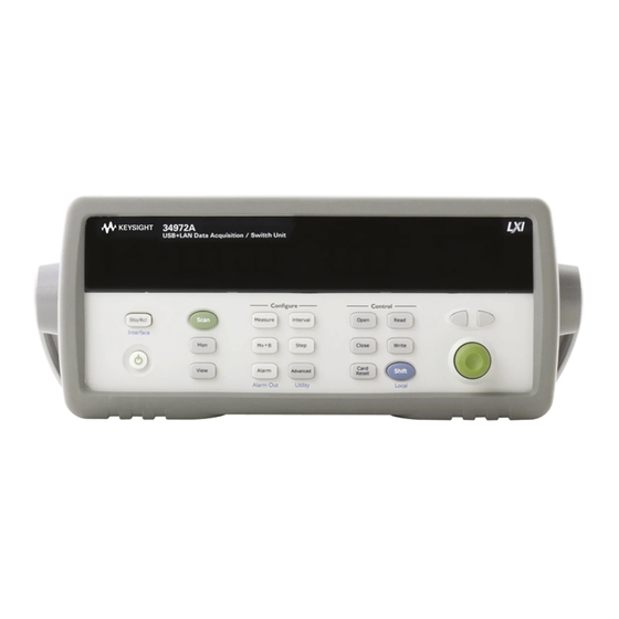
Page 11: The Front Panel At A Glance
Scaling Configuration Menu 11 View Scanned Data, Alarms, Errors Menu Alarm / Alarm Output Configuration Menu 12 Shift / Local Key Scan-to-Scan Interval Menu 13 Knob Scan List Single Step / Read Key 14 Navigation Arrow Keys Keysight 34970A/34972A Service Guide... -
Page 12: The Front-Panel Menu At A Glance
2 Press the same menu key again to move to the next item of the menu. Typically, this is where you choose parameter values for the selected operation. Keysight 34970A/34972A Service Guide... - Page 13 A brief confirmation message is displayed. Tip: To review the current configuration of a specific menu, press the NOTE menu key several times. A message NO CHANGES is displayed when you exit the menu. Keysight 34970A/34972A Service Guide...
-
Page 14: Display Annunciators
Viewed data is the minimum reading stored during most recent scan. Viewed data is the maximum reading stored during most recent scan. SHIFT has been pressed. Press again to turn off. 4-wire function is in use on displayed channel. Offset compensation is enabled on displayed channel. Keysight 34970A/34972A Service Guide... - Page 15 Alarms are enabled on displayed channel. Mx+B scaling is enabled on displayed channel. HI or LO alarm condition has occurred on indicated alarms. Keysight 34970A/34972A Service Guide...
-
Page 16: The 34970A Rear Panel At A Glance
The 34970A Rear Panel at a Glance Power-Line Fuse-Holder Assembly Slot Identifier (100,200, 300) Power-Line Voltage Setting Ext Trig Input / Alarm Outputs / Channel Advance Input / Channel Closed Output Chassis Ground Screw RS-232 Interface Connector GPIB (IEEE-488) Interface Connector... -
Page 17: The 34972A Rear Panel At A Glance
For protection from electrical shock, the power cord ground must not be WARNING defeated. If only a two-contact electrical outlet is available, connect the instrument’s chassis ground screw (see above) to a good earth ground. Keysight 34970A/34972A Service Guide... -
Page 18: The Plug-In Modules At A Glance
When making four-wire resistance measurements, channels from Bank A are automatically paired with channels from Bank B. You can close multiple channels on this module only if you Keysight 34970A/34972A Service Guide... - Page 19 34905/6A Dual 4-Channel RF Multiplexers – 34905A (50Ω) / 34906A (75Ω) – 2 GHz bandwidth with on-board SMB connections – 1 GHz bandwidth with SMB-to-BNC adapter cables provided – For detailed information and a module diagram, see page 158. Keysight 34970A/34972A Service Guide...
-
Page 20: A Multifunction Module
– For detailed information and a module diagram, see page 160. Use this module for high-density switching applications which require single-wire inputs with a common LO. All relays are break-before-make to ensure that only one relay is connected at any time. Keysight 34970A/34972A Service Guide... -
Page 21: In This Book
Technologies for servicing, or for servicing it yourself. It also contains a list of replaceable parts. If you have questions relating to the operation of the 34970A/34972A, call 1-800-452-4844 in the United States, or contact your nearest Keysight Technologies Sales Office. - Page 22 THIS PAGE HAS BEEN INTENTIONALLY LEFT BLANK. Keysight 34970A/34972A Service Guide...
-
Page 23: Table Of Contents
........14 The 34970A Rear Panel at a Glance . - Page 24 ......... 69 Keysight 34970A/34972A Service Guide...
- Page 25 ........122 Keysight 34970A/34972A Service Guide...
- Page 26 ..........164 Keysight 34970A/34972A Service Guide...
- Page 27 .......194 Parts List for 34970A/34972A and 34901A ....194...
- Page 28 THIS PAGE HAS BEEN INTENTIONALLY LEFT BLANK. Keysight 34970A/34972A Service Guide...
-
Page 29: Specifications
Keysight 34970A/34972A Data Acquisition/Switch Unit Service Guide Specifications For the specifications and characteristics of the 34970A/34972A Data Acquisition/Switch Unit, refer to the datasheet at http://literature.cdn.keysight.com/litweb/pdf/5965-5290EN.pdf... -
Page 30: 1 Specifications
Specifications THIS PAGE HAS BEEN INTENTIONALLY LEFT BLANK. Keysight 34970A/34972A Service Guide... - Page 31 Keysight 34970A/34972A Data Acquisition/Switch Unit Service Guide Quick Start Quick Start To Prepare the Instrument for Use To Connect Wiring to a Module To Set the Time and Date To Configure a Measurement Channel To Monitor a Single Channel To Close a Channel...
-
Page 32: Quick Start
“To Close a Channel” on page 39 – “If the Instrument Does Not Turn On” on page 41 – “To Adjust the Carrying Handle” on page 43 – “To Rack Mount the Instrument” on page 44 Keysight 34970A/34972A Service Guide... -
Page 33: To Prepare The Instrument For Use
To Prepare the Instrument for Use 1 Check the list of supplied items. Verify that you have received the following items with your instrument. If anything is missing, contact your nearest Keysight Technologies Sales Office. – One power cord. – One User’s Guide. -
Page 34: To Connect Wiring To A Module
– Use shielded twisted pair PTFE insulated cables to reduce settling and noise errors. – The diagrams on the next page show how to connect wiring to a multiplexer module for each measurement function. Keysight 34970A/34972A Service Guide... - Page 35 DC Voltage / AC Voltage / Frequency Thermocouple Types: B, E, J, K, N, R, S, T Ranges: 100 mV, 1 V, 10 V, 100 V, 300 V See the 34970A/34972A User’s Guide for thermocouple color codes. 2-Wire Ohms / RTD / Thermistor 4-Wire Ohms / RTD Ω...
-
Page 36: To Set The Time And Date
You can also edit the AM/PM field. TIME 03:45 PM 2 Set the date. to select the field to modify and turn the knob to change the value. JUN 01 2002 Keysight 34970A/34972A Service Guide... -
Page 37: To Configure A Measurement Channel
(full bright) setting for each parameter. The menu will time-out after about 20 seconds of inactivity and any changes NOTE made previously will take effect. Keysight 34970A/34972A Service Guide... -
Page 38: To Monitor A Single Channel
This includes any combination of temperature, voltage, resistance, current, frequency, or period measurements on multiplexer channels. You can also monitor a digital input port or the totalizer count on the multifunction module. To disable monitoring, press again. Keysight 34970A/34972A Service Guide... -
Page 39: To Close A Channel
Plug-In Module 34901A 20-Channel Mux 34902A 16-Channel Mux 34908A 40-Channel Single-Ended Mux 34903A 20-Channel Actuator 34904A 4x8 Matrix 34905A Dual 4-Channel RF Mux (50Ω) 34906A Dual 4-Channel RF Mux (75Ω) 34907A Multifunction Module (DIO) Keysight 34970A/34972A Service Guide... - Page 40 34907A Multifunction Module (Totalizer) 34907A multifunction Module (DAC) [a] Only one channel can be closed at a time on this module. [b] Only one channel in each bank can be closed at a time on this module. Keysight 34970A/34972A Service Guide...
-
Page 41: If The Instrument Does Not Turn On
The instrument is shipped from the factory with a 500 mA fuse installed. This is the correct fuse for all line voltages. See the next page if you need to replace the power-line fuse. To replace the 500 mAT, 250 V fuse, order Keysight part number 2110-0458. NOTE Keysight 34970A/34972A Service Guide... - Page 42 4 Replace the fuse-holder assembly in the rear correct voltage appears in the window. panel. 100, 120 (127), 220 (230), or 240 VAC Verify that the correct line voltage is selected and the power-line fuse is good. Keysight 34970A/34972A Service Guide...
-
Page 43: To Adjust The Carrying Handle
Quick Start To Adjust the Carrying Handle To adjust the position, grasp the handle by the sides and pull outward. Then, rotate the handle to the desired position. Bench-top viewing position Carrying position Keysight 34970A/34972A Service Guide... -
Page 44: To Rack Mount The Instrument
Instructions and mounting hardware are included with each rack-mounting kit. Any Keysight System II instrument of the same size can be rack-mounted beside the 34970A/34972A. Remove the carrying handle, and the front and rear rubber bumpers, before NOTE rack-mounting the instrument. - Page 45 5063-9212. Be sure to use the support rails inside the rack cabinet. To install one or two instruments in a slid ing support shel f, order shel f 5063-9255, and slide kit 1494-0015 (for a single instrument, also order filler panel 5002-3999). Keysight 34970A/34972A Service Guide...
- Page 46 Quick Start THIS PAGE HAS BEEN INTENTIONALLY LEFT BLANK. Keysight 34970A/34972A Service Guide...
- Page 47 Keysight 34970A/34972A Data Acquisition/Switch Unit Service Guide Front-Panel Overview Front-Panel Overview Front-Panel Menu Reference To Unsecure for Calibration To Secure Against Calibration To Change the Security Code Error Messages To Perform a Zero Adjustment To Apply Mx+B Scaling to Measurements...
-
Page 48: Front-Panel Overview
It does, however, give you an overview of the front-panel menus and many front-panel operations. See the Keysight 34970A/34972A User’s Guide for a complete discussion of the instrument’s capabilities and operation. -
Page 49: Front-Panel Menu Reference
– Clear the state of the four alarm output lines. – Select the “Latch” or “Track” mode for the four alarm output lines. – Select the slope (rising or falling edge) for the four alarm output lines. Keysight 34970A/34972A Service Guide... - Page 50 – View the first 20 alarms in the alarm queue (reading and time alarm occurred). – View up to 10 errors (34970A) or 20 errors (34972A) in the error queue. – Read the number of cycles for the displayed relay (relay maintenance feature).
- Page 51 – Assign a name to each storage location. – Recall stored states, power-down state, factory reset state, or preset state. Configure the remote interface (34970A). – Select the GPIB address. – Configure the RS-232 interface (baud rate, parity, and flow control).
-
Page 52: To Unsecure For Calibration
When you return to the menu, you will see new choices CAL UNSECURED and SECURE CAL. If you enter the wrong secure code, NO MATCH is displayed and a new choice, NOTE EXIT, is shown. Keysight 34970A/34972A Service Guide... -
Page 53: To Secure Against Calibration
UNSECURED and SECURE CAL. To secure the instrument, select SECURE CAL and press . After entering the desired security code, press again. When you return to the menu, you will see new choices CAL SECURED and UNSECURE CAL. Keysight 34970A/34972A Service Guide... -
Page 54: To Change The Security Code
Go to the SECURE CAL entry, enter the new security code, and press (the instrument is now secured with the new code). Changing the code from the front panel also changes the code as seen from the remote interface. Keysight 34970A/34972A Service Guide... -
Page 55: Error Messages
A list of the self-test errors messages and their meanings begins on page 179. For a complete list of error messages and descriptions, see Chapter 6 in the 34970A/34972A User’s Guide. Keysight 34970A/34972A Service Guide... -
Page 56: To Perform A Zero Adjustment
For the Zero Adjustment, the input value is 0.000000. +000.000,000 mVDC 5 Begin the ad justment. The display will show the progress of the adjustment. When all the adjustments are completed, the display will show done. DONE Keysight 34970A/34972A Service Guide... -
Page 57: To Apply Mx+B Scaling To Measurements
You can specify an optional three-character label for your scaled readings (RPM, PSI, etc.). The default label is the standard engineering unit for the selected function (VDC, OHM, etc.). LABEL AS OHM 4 Scaling is now applied to the measurements. Keysight 34970A/34972A Service Guide... -
Page 58: To Read The Relay Cycle Count
For example, the relay count will always be the same on channels 01 and 21. – For more information on relay life and load considerations, refer to “Relay Life and Preventative Maintenance” in the 34970A/34972A User’s Guide. – To read the count on the active channel, choose the following item and then turn the knob. -
Page 59: To Read A Digital Input Port
The bit pattern read from the port will be displayed until you press another key, turn the knob, or until the display times out. To add a digital input channel to a scan list, press and select the DIO READ NOTE choice. Keysight 34970A/34972A Service Guide... -
Page 60: To Write To A Digital Output Port
Decimal Display Shown 240 DOUT 4 Output the bit pattern to the specified port. The specified bit pattern is latched on the specified port. To cancel an output operation in progress, wait for the display to time out. Keysight 34970A/34972A Service Guide... -
Page 61: To Read The Totalizer Count
The count will be displayed until you press another key, turn the knob, or until the display times out. To manually reset the totalizer count, press To add a totalizer channel to a scan list, press and select the TOT READ choice. NOTE Keysight 34970A/34972A Service Guide... -
Page 62: To Output A Dc Voltage
+05.250VDAC 4 Output the voltage from the selected DAC. The output voltage will be displayed until you press another key or turn the knob. To manually reset the output voltage to 0 volts, press Keysight 34970A/34972A Service Guide... - Page 63 Keysight 34970A/34972A Data Acquisition/Switch Unit Service Guide Calibration Procedures Calibration Procedures Keysight Technologies Calibration Services Calibration Interval Time Required for Calibration Automating Calibration Procedures Recommended Test Equipment Input Connections Calibration Security Calibration Message Calibration Count Calibration Procedure Aborting a Calibration in Progress...
-
Page 64: Calibration Procedures
“–10 VDC Adjustment Procedure (Optional)” on page 92 – “Plug-in Module Test Considerations” on page 94 – “Relay Verification” on page 95 – “Thermocouple Reference Junction (Optional)” on page 119 – “34907A Analog Output” on page 122 Keysight 34970A/34972A Service Guide... - Page 65 The new correction factors are stored in non-volatile memory until the next calibration adjustment is performed. Non-volatile EEPROM calibration memory does not change when power has been off or after a remote interface reset. Keysight 34970A/34972A Service Guide...
-
Page 66: Keysight Technologies Calibration Services
Whatever calibration interval you select, Keysight recommends that complete re-adjustment should always be performed at the calibration interval. This will assure that the 34970A/34972A will remain within specification for the next calibration interval. This criteria for re-adjustment provides the best long-term stability. -
Page 67: Time Required For Calibration
Calibration Procedures Time Required for Calibration The 34970A/34972A can be automatically calibrated under computer control. With computer control you can perform the complete calibration procedure and performance verification tests in less than 30 minutes once the instrument is warmed-up (see “Test Considerations”... -
Page 68: Recommended Test Equipment
All switch modules [a] In addition to the internal DMM, these applications require an input multiplexer module. The Keysight 34901A is recommended. [b] Thermistor YSI 44031 is available as Keysight part number 34308A (package of five). Keysight 34970A/34972A Service Guide... -
Page 69: Input Connections
To use a 34901A to completely verify and adjust the internal DMM, make the following connections: Connections for Connections for Connections for DC V, AC V, DC/AC Current 4-wire Ohms 2- and 4-wire Ohms Copper Short 34901A Calibrator Keysight 34970A/34972A Service Guide... - Page 70 You cannot test or adjust current inputs with a 34902A. If you use a 34902A, connect the copper shorts to Channels 7 and 15 and make the input connections to Channels 8 and 16. Keysight 34970A/34972A Service Guide...
-
Page 71: Calibration Security
( _ ). You do not have to use all 12 characters but the first character must always be a letter. If you forget your security code, you can disable the security feature by adding a NOTE jumper inside the instrument as described on the following page. Keysight 34970A/34972A Service Guide... -
Page 72: To Unsecure The Instrument Without The Security Code
2 Remove the instrument cover (see page 184). Turn the instrument over. 3 Apply power and turn on the instrument. Be careful not to touch the power line connections. – Exposed Mains WARNING – Do not Touch! Keysight 34970A/34972A Service Guide... - Page 73 5 While maintaining the short, enter any unsecure code. The instrument is now unsecured. 6 Remove the short. 7 Turn off the instrument and remove the power cord. Reassemble the instrument. Now you can enter a new security code. Be sure to remember the new security code. Keysight 34970A/34972A Service Guide...
-
Page 74: Calibration Message
– The calibration count is also incremented with calibrations of the DAC channels on the multifunction module. – Front-Panel Operation: CAL COUNT – Remote Interface Operation: CALibration:COUNt? Keysight 34970A/34972A Service Guide... -
Page 75: Calibration Procedure
Typically, upon re-applying power, the instrument will report error 705 Cal:Aborted. You may also generate errors 740 through 746. If this occurs, you should not use the instrument until a complete re-adjustment has been performed. Keysight 34970A/34972A Service Guide... -
Page 76: Test Considerations
“0” output is correct. If necessary, the measurements can be referenced to the calibrator’s “0” output using Mx + B scaling (see page 57). You will need to set the offset for each range of the measuring function being verified. Keysight 34970A/34972A Service Guide... -
Page 77: Performance Verification Tests
An extensive set of tests that are recommended as an acceptance test when you first receive the instrument or after performing adjustments. Optional Verification Tests Tests not performed with every calibration. Perform these tests to verify additional specifications or functions of the instrument. Keysight 34970A/34972A Service Guide... -
Page 78: Self-Test
– If the self-test fails, “FAIL” is displayed and the ERROR annunciator turns on. If repair is required, see Chapter 6, "Service" for further details. – If all tests pass, you have a high confidence (~90%) that the instrument is operational. Keysight 34970A/34972A Service Guide... -
Page 79: Quick Performance Check
If the instrument fails performance verification, adjustment or repair is required. Adjustment is recommended at every calibration interval. If adjustment is not made, you must guard band, using no more than 80% of the specifications listed Chapter 1, as the verification limits. Keysight 34970A/34972A Service Guide... -
Page 80: Internal Dmm Verification Tests
Open 10 mA ± 1 mA ± 2 mA ± 2 mA Open DC Current 100 mA ± 4 mA ± 5 mA ± 5 mA Open ± 60 mA ± 100 mA ± 100 mA Keysight 34970A/34972A Service Guide... - Page 81 [c] For 2-wire ohms, an additional 4W of error must be added. Zero offset calibration using a multifunction calibrator is NOT recommended. NOTE The calibrator and cabling offset can be large and unstable causing poor offset calibration of the internal DMM. Keysight 34970A/34972A Service Guide...
-
Page 82: Gain Verification
± 30 W ± 90 W ± 110 W 4-Wire Ohms 10 MW 10 MW ± 1.6 kW ± 2.1 kW ± 4.1 kW 100 MW ±310 kW ± 810 kW ± 810 kW 100 MW Keysight 34970A/34972A Service Guide... - Page 83 [d] The 2-wire ohms resistance verification test is optional (see note on page 89). For 2-wire ohms, an additional 1 W of error must be added (see page 29). Add a 1-second channel delay when using Fluke 5700 in 2-wire compensated mode. This avoids response time issues with 2-wire compensation when 34970A/34972A’s current source contains a pulse.
- Page 84 [c] Some calibrators may have difficulty driving the internal DMM and cable load at this V-Hz output. Use short, low capacitance cable to reduce calibration loading. Verification can be performed at >195 Vrms. New test limits can be computed from the accuracy specification shown in Chapter 1 for the actual test conditions used. Keysight 34970A/34972A Service Guide...
- Page 85 1 kHz ± 1.41 mA ± 1.41 mA ± 1.41 mA 10 mA 1 kHz ± 1.4 mA ± 1.4 mA ± 1.4 mA [a] Q: Quick performance verification test points. [b] Verify only, no adjustment. Keysight 34970A/34972A Service Guide...
- Page 86 ± 0.1 Hz 10 mV 100 kHz ± 6 Hz ± 10 Hz ± 10 Hz [a] Q: Quick performance verification test points. [b] Verify only, no adjustment. For this test, isolate the calibrator’s output from earth ground. Keysight 34970A/34972A Service Guide...
-
Page 87: Optional Ac Performance Verification Tests
± 7 mV ± 9 mV ± 10 mV 1 kHz 10 V ± 3.4 mV ± 4.5 mV ± 4.6 mV 100 mV 1 kHz 10 V ± 13 mV ± 14 mV ± 14.06 mV Keysight 34970A/34972A Service Guide... -
Page 88: Internal Dmm Adjustments
4 Use the knob and arrow keys to set the number in the display to 0.000000 and press 5 Perform the Zero Offset Verification tests (see page 80) to check zero calibration results. Keysight 34970A/34972A Service Guide... -
Page 89: Gain Adjustment
Perform the DC voltage gain calibration before the AC voltage gain calibration. Never turn off the instrument during a Gain Adjustment. This may cause NOTE calibration memory for the present function to be lost. Keysight 34970A/34972A Service Guide... - Page 90 1 kHz - 100 kHz [a] Valid frequencies are as follows: 1 kHz ± 10% for the 1 kHz calibration, 45 kHz - 100 kHz for the 50 kHz calibration, and 10 Hz ± 10% for the 10 Hz calibration. Keysight 34970A/34972A Service Guide...
- Page 91 6 Perform the appropriate Gain Verification Test to check the calibration results. 7 Repeat steps 1 through 6 for each gain verification test point shown in the tables. Each range in the gain adjustment procedure takes less than NOTE 20 seconds to complete. Keysight 34970A/34972A Service Guide...
-
Page 92: Vdc Adjustment Procedure (Optional)
+10V. Allow enough settling time for any thermal offset voltages to stabilize (usually about 1 minute). 5 Perform a +10V DC gain calibration. Press to enter the calibration menu. Press again to begin the adjustment procedure. Keysight 34970A/34972A Service Guide... - Page 93 (from step 3) and press Using the previous example values, enter 10 µV minus 10.001 volts or –10.000990 volts. 10 When the adjustment finishes, verify that new readings fall within ± 30 µV of the calibrator output minus the offset. Keysight 34970A/34972A Service Guide...
-
Page 94: Plug-In Module Test Considerations
Keep the input cables as short as possible. – Remove all user wiring and connections from the plug-in modules before verification or adjustment. – Use 4-wire Ohms measurement techniques for checking relay contact resistance. Check directly at the terminals where possible. Keysight 34970A/34972A Service Guide... -
Page 95: Relay Verification
– For more information on relay life and load considerations, refer to “Relay Life and Preventative Maintenance” in Chapter 8 of the 34970A/34972A User’s Guide. – A procedure to read the relay cycle count is given on page 58. -
Page 96: (Optional) 34901A Relay Contact Resistance Verification
See the diagram on page 97 for the required connections for each test (be sure to probe the components at the indicated location). For these measurements, the 34901A is not installed in the 34970A/34972A. Record the 4-wire ohms measurements from the external DMM in the table below. - Page 97 Note: Be sure to probe the components at the indicated locations on the module. Probe here for L402 measurement. Probe here for F501 measurement. Probe here for F502 measurement. Connections for 34901A Verification Tests 1 through 5 Keysight 34970A/34972A Service Guide...
- Page 98 Make the connections to the 34901A as shown in the diagram below. Be sure to route your wiring for proper strain relief and install the module cover. Install the 34901A in slot 200 of the 34970A/34972A. Open all channels on the module by performing a Factory Reset (press and select “Recall State”;...
- Page 99 DMM in the following table. External DMM Ohmmeter Connections Channel Test Test # Measured Value Relay Measured Configured Limit HI Sense LO Sense Ch 10 ________Ohms — — Subtract (Test 9 - Test 3) ________Ohms 2.00 W K423 Keysight 34970A/34972A Service Guide...
- Page 100 K414 Ch 15 ________Ohms 2.00 W K415 Ch 16 ________Ohms 2.00 W K416 Ch 17 ________Ohms 2.00 W K417 Ch 18 ________Ohms 2.00 W K418 Ch 19 ________Ohms 2.00 W K419 Ch 21 ________Ohms — — Keysight 34970A/34972A Service Guide...
- Page 101 Ch 21 L Ch 21 I Ch 21 L ________Ohms — — Ch 22 Subtract (Test 35 - Test 4) ________Ohms 2.00 W K523 [a] The latching relays remain closed when the module is removed from the 34970A/34972A. Keysight 34970A/34972A Service Guide...
- Page 102 Open all channels on the module by performing a Factory Reset. Close Channel 21 (module in slot 200). Remove the 34901A from the 34970A/34972A and do not reinstall it for the remaining tests. Using the external DMM, make a 4-wire ohms measurement between the and I terminals on Channel 22.
-
Page 103: (Optional) 34902A Relay Contact Resistance Verification
See the diagram on page 104 for the required connections for each test (be sure to probe the components at the indicated location). For these measurements, the 34902A is not installed in the 34970A/34972A. Record the 4-wire ohms measurements from the external DMM in the table below. - Page 104 Calibration Procedures Probe here for L302 and L301 measurements. Connections for 34902A Verification Tests 1 through 4 Keysight 34970A/34972A Service Guide...
- Page 105 Make the connections to the 34902A as shown in the diagram below. Be sure to route your wiring for proper strain relief and install the module cover. Install the 34902A in slot 200 of the 34970A/34972A. Open all channels on the module by performing a Factory Reset (press and select “Recall State”;...
- Page 106 DMM in the following table. External DMM Ohmmeter Connections Channel Test Test # Measured Value Relay Measured Configured Limit HI Sense LO Sense Ch 08 ________Ohms — — Subtract (Test 9 - Test 4 ________Ohms 2.00 W K328 Keysight 34970A/34972A Service Guide...
- Page 107 Ch 16 & 15 ________Ohms 2.00 W — Subtract (Test 26 - Test 25) ________Ohms 2.00 W K316 [a] Only the channel currently under test should be closed at one time. All other channels should be open. Keysight 34970A/34972A Service Guide...
-
Page 108: (Optional) 34903A Relay Contact Resistance Verification
“Plug-in Module Test Considerations” on page 94. 2 Install the 34903A module in slot 100. Close Channels 01 through 20. Remove the module from the 34970A/34972A. 3 Measure the resistance from the terminal to the NO terminal on each channel. -
Page 109: (Optional) 34904A Relay Contact Resistance Verification
( through ). Be sure to route your wiring for ROW1 ROW4 proper strain relief and install the module cover. Install the 34904A in slot 200 of the 34970A/34972A. Connections for 34904A Verification Tests Keysight 34970A/34972A Service Guide... - Page 110 ________Ohms 2.00 W K204 Ch 25 & 45 ________Ohms 2.00 W K205 Ch 26 & 46 ________Ohms 2.00 W K206 Ch 27 & 47 ________Ohms 2.00 W K207 Ch 28 & 48 ________Ohms 2.00 W K208 Keysight 34970A/34972A Service Guide...
- Page 111 K406 Ch 47 & 17 ________Ohms 2.00 W K407 Ch 48 & 18 ________Ohms 2.00 W K408 [a] Only the channel currently under test should be closed at one time. All other channels should be open. Keysight 34970A/34972A Service Guide...
-
Page 112: (Optional) 34905/06A Relay Contact Resistance Verification
7 Repeat steps 2, 3, 4, 5, and 6 for the channels connected to COM2. In general, a new relay should have a contact resistance of less than 0.5 W. NOTE Relays with contact resistance in excess of 1 W should be replaced. Keysight 34970A/34972A Service Guide... -
Page 113: (Optional) 34908A Relay Contact Resistance Verification
See the diagram on page 114 for the required connections for this test (be sure to probe the inductor at the indicated location). For this measurement, the 34908A is not installed in the 34970A/34972A. Record the 4-wire ohms measurements from the external DMM in the table below. - Page 114 Calibration Procedures Note: Be sure to probe from the right-hand side of the inductor. Connections for 34908A Verification Test 1 Keysight 34970A/34972A Service Guide...
- Page 115 Make the connections to the 34908A as shown in the diagram below. Be sure to route your wiring for proper strain relief and install the module cover. Install the 34908A in slot 200 of the 34970A/34972A. Open all channels on the module by performing a Factory Reset (press and select “Recall State”;...
- Page 116 Be sure to route your wiring for proper strain relief and install the module cover. Install the 34908A in slot 200 of the 34970A/34972A. Connections for 34908A Verification Tests 4 through 43 Keysight 34970A/34972A Service Guide...
- Page 117 L Com ________Ohms 2.00 W K420, K422 Ch 21 H Com L Com H Com L Com ________Ohms 2.00 W K401, K422 Ch 22 H Com L Com H Com L Com ________Ohms 2.00 W K402, K422 Keysight 34970A/34972A Service Guide...
- Page 118 [a] Only the channel currently under test should be closed at one time. All other channels should be open. If the first 20 or last 20 relays have high resistance values, it is likely that relay NOTE K422 is bad. Keysight 34970A/34972A Service Guide...
-
Page 119: Thermocouple Reference Junction (Optional)
4 Place the J Type calibrated thermocouple at a known temperature (ice bath or calibrator). 5 Select Channel 110 (or 108). Configure the channel as follows: TEMPERATURE THERMOCOUPLE J TYPE INTEG 10 PLC (Advanced menu) INTERNAL REF (Advanced menu) Keysight 34970A/34972A Service Guide... -
Page 120: Thermocouple Reference Junction Adjustments
For the 34901A Channels 6 and 17 For the 34902A Channels 6 and 11 For the 34908A Channels 6 and 16 Keep the thermistor leads as short as possible. Locate the thermistor as near to the input connectors as possible. 34901A Keysight 34970A/34972A Service Guide... - Page 121 (or use the ROUTe:MON command from the remote interface). 4 Press to enter the calibration menu. Press again to begin the adjustment procedure. 5 Verify the adjustment (see page 119). Keysight 34970A/34972A Service Guide...
-
Page 122: 34907A Analog Output
This procedure is used to check the calibration of the analog outputs on the 34907A Multifunction Module. Install the module in slot 200. Verification checks are performed only for those output values with unique calibration constants. 1 Make connections to analog output channels as shown below. To DMM 34907A Keysight 34970A/34972A Service Guide... -
Page 123: Analog Output Adjustment
9 Repeat steps 1 through 8 for Channel 105. 10 Perform the Voltage Output Verification Test on page 110 to verify the adjustment. Keysight 34970A/34972A Service Guide... - Page 124 Calibration Procedures THIS PAGE HAS BEEN INTENTIONALLY LEFT BLANK. Keysight 34970A/34972A Service Guide...
-
Page 125: 5 Theory Of Operation
Keysight 34970A/34972A Data Acquisition/Switch Unit Service Guide Theory of Operation Theory of Operation System Block Diagram Floating Logic Memory Earth-Referenced Logic Power Supplies Front Panel Backplane Internal DMM Switch Modules Multifunction Module... -
Page 126: Theory Of Operation Theory Of Operation
Theory of Operation Theory of Operation This chapter is organized to provide descriptions of the circuitry contained on each schematic shown in Chapter 8 of the 34970A/34972A User’s Guide. A block diagram overview is provided. – “System Block Diagram” on page 127 –... -
Page 127: System Block Diagram
A simplified block diagram is shown below. Not all systems have an Internal DMM. In these systems, the internal DMM connections to the analog bus and the floating logic are left open. The major portions of each block are described in the following sections. Keysight 34970A/34972A Service Guide... -
Page 128: Floating Logic
– Provides automatic switch over to the battery BT101 for the +5V_NV supply when the 5V_FLT supply drops below the battery voltage. – Blocks the main controller’s write signal (WR_N) while the 5V_FLT supply is below operating level. Keysight 34970A/34972A Service Guide... - Page 129 All other frequencies will result in the use of a 50 Hz standard. – A 16-bit counter counts pulses on CNT to create, along with the 8-bit counter in U209, a 24-bit counter for the internal DMM. Keysight 34970A/34972A Service Guide...
- Page 130 A4U450 to completely calibrate the internal DMM. The two devices, although on different assemblies, share the same I/O signals, CALSCK and CALDAT, that allow them to be read (and written) by U205. Keysight 34970A/34972A Service Guide...
-
Page 131: Memory
U402, U403, U404, U405, and U410. A uniform, 256Kx16, memory block is formed by the four 128Kx8 devices, U402 through U405. A separate, 32Kx8 block is formed by U410 and is available through special programming of U209. Keysight 34970A/34972A Service Guide... -
Page 132: Earth-Referenced Logic
U306B, U306C, U306D, and U306E drive the alarm outputs. The alarm is a low true signal at the sub miniature D connector on the rear panel. U306F drives the channel closed output signal. The external trigger input is buffered by U304C and U304D. Keysight 34970A/34972A Service Guide... -
Page 133: Power Supplies
A separate winding of T1 provides a center tapped 6 Vrms filament supply for the display. Q110A and Q110B turn on and off the filament supply in response to the FILPWR signal from the main controller through U107A. Keysight 34970A/34972A Service Guide... - Page 134 +5V_BP supply to ensure that when power is turned off no voltages are present at the interfaces. The +5V_ER supply is switched by Q101A and Q101B to create the +5V_BP (backplane) and fan power supplies. Undervoltage sensor U102 provides the earth reference controller reset at initial power on. Keysight 34970A/34972A Service Guide...
-
Page 135: Front Panel
A1U205. In turn, A1U205 takes actions that either place the instrument in the “standby mode” or “on” mode. In “standby”, both the filament supply to the front panel and the +5V_BP supply to the backplane, rear panel interfaces, and fan are turned off. Keysight 34970A/34972A Service Guide... -
Page 136: Backplane
Earth referenced digital ground. +5 V A3, B3, C3 Earth referenced module power supply. Earth Ground A1, B1, C1 Earth referenced zap return ground. Module reset from the earth referenced logic. Module service request to the earth referenced logic. Keysight 34970A/34972A Service Guide... -
Page 137: Internal Dmm
Theory of Operation Internal DMM DMM Block Diagram A portion of the internal DMM block diagram is shown below. Backplane Main Controller Keysight 34970A/34972A Service Guide... -
Page 138: Input
[a] K104 will be reset when input resistance is selected to >10,000 MW through the menu. [b] K104 will be set for the 100 MW range. [c] Configurations shown are for the current source output (HI) terminal. The measurement sense is accomplished through the Sense HI / Sense LO terminals. Keysight 34970A/34972A Service Guide... -
Page 139: Input Amplifier
U101 Input Amplifier Gain ADC Input 100 mV Pin 5 x100 10 V Pin 5 10 V 10 V Pin 5 10 V 100 V 1/100 Pin 8 10 V 1000V 1/100 Pin 8 10 V Keysight 34970A/34972A Service Guide... - Page 140 DC amplifier gain for each resistance range are tabulated below. Ohms Range Vol tage Across R Amplifier Gain ADC Input 100 W 100 mV x100 10 V 1 kW to 100 kW 10 V 1 MW 10 MW 100 MW 4.5 V 4.5 V Keysight 34970A/34972A Service Guide...
-
Page 141: Ohms Current Source
500 kW 1 MW 5 mA R202 1 MW 10 MW 500 nA 14 V R201 1 MW 10 V R201 1 MW 100 MW 500 nA [a] Measured in parallel with the internal 10 MW resistor. Keysight 34970A/34972A Service Guide... -
Page 142: Ac Circuit
The 1st stage is a compensated attenuator implementing a gain of x0.2 or x0.002 as selected by U304A and U304D. Each voltage range has a unique 50 kHz frequency response correction produced by a programmable variable capacitor connected across R304. Keysight 34970A/34972A Service Guide... - Page 143 CPU’s 10-bit ADC during frequency or period measurements. This lower resolution measurement is sufficient to perform voltage ranging decisions for these functions. The frequency comparator output is disabled during AC voltage and current measurements by U310B forcing U310A’s input to –15 volts. Keysight 34970A/34972A Service Guide...
-
Page 144: A-To-D Converter
The integrator amplifier is formed by U402 and U420. Resistors R420 and R421 affect the amplifier stability. Amplifier oscillation may occur if their values are incorrect. Amplifier U420 improves the offset voltage characteristics of integrator amplifier U402. Keysight 34970A/34972A Service Guide... - Page 145 +7 V during power up. IC U400A amplifies the voltage reference to +10 V while amplifier U401A inverts the +10 V reference to –10 V. The reference voltages force precision slope currents for the integrating ADC through U102E–R17, R18. Keysight 34970A/34972A Service Guide...
-
Page 146: Switch Modules
16 Channel Reed MUX with T/C Compensation 34903A 20 Channel Actuator 34904A 4 X 8 Matrix Switch 34905A 50 W Dual 4:1 VHF MUX 34906A 75 W Dual 4:1 VHF MUX 34908A 40 Channel Single-Ended MUX with T/C Compensation Keysight 34970A/34972A Service Guide... -
Page 147: Switch Module Control
– DATA OUT, from the module controller to the Floating Logic A1U205 via the opto-isolator A1U213. This line is a wired-OR line that can be driven by any module. Keysight 34970A/34972A Service Guide... - Page 148 (DR_EN and +5NL_EN) that connect Vcc from the digital bus with the relay drive lines through Q101 (+5R or +5NL). To minimize the current through DGND caused by static discharge, the ground return (ZGND) is isolated from the backplane ground through a bead L102. Keysight 34970A/34972A Service Guide...
-
Page 149: Relay Drivers
The polarity of the current flow through the latching relay coil determines the set (closed) or reset (open) position of the relay contacts. Latching relays are driven by row and column latches or complimentary transistor pairs. Keysight 34970A/34972A Service Guide... - Page 150 Switch Module Open Close 34901A 6 ms 6 ms 34902A 0.40 ms 1.25 ms 34903A 6 ms 6 ms 34904A 6 ms 6 ms 34905A/06A 10 ms 15 ms 34908A 6 ms 6 ms Keysight 34970A/34972A Service Guide...
-
Page 151: 34901A
The control circuitry has four groupings of latches, relay drivers and relays. The three control lines (SEL_A, SEL_B, and SEL_C) from the module controller are divided into five control lines by the binary to octal converter U109. Keysight 34970A/34972A Service Guide... - Page 152 The current measurement channels are selected by relay K522. Relays K523 and K524 short the inputs when a channel is not selected. Relay K521 makes the connection to the analog bus for measurement by the Internal DMM. Keysight 34970A/34972A Service Guide...
-
Page 153: 34902A
Tree switching controls the 2-wire/4-wire Ohms operation and connections to the analog bus. The reed relays are non-latching and the relay driver and +5R is applied while a channel is closed. Keysight 34970A/34972A Service Guide... - Page 154 Ohms multiplexing where the Ohms current source is connected to channels 1 through 8 and the sense is obtained from channels 9 through 16. Relays K326 and K328 control the connection to the analog bus for measurements using the internal DMM. Keysight 34970A/34972A Service Guide...
-
Page 155: 34903A
Each group of row drivers controls five relays. The column drivers operate as a pair. There are ten column drivers each controlling two relays. The 34903A provides 20 channels of Form C switching. Keysight 34970A/34972A Service Guide... -
Page 156: 34904A
Theory of Operation 34904A Components in this discussion are located on the A1 circuit assembly (34904-66501). The control circuitry has four groupings of latches, relay drivers and relays divided into 4 rows by 8 columns. Keysight 34970A/34972A Service Guide... - Page 157 Each group of row drivers controls eight relays. The column drivers operate as a pair. There are eight column drivers each controlling four relays. The relays are arranged in 4 rows by 8 columns. Keysight 34970A/34972A Service Guide...
-
Page 158: 34905A/34906A
Theory of Operation 34905A/34906A Components in this discussion are located on the A1 circuit assembly (34905-66501 or 34906-66501). The control circuitry has of two grouping of buffers, relay drivers and relays, one for each multiplexer bank. Keysight 34970A/34972A Service Guide... - Page 159 Each set and reset driver controls one relay. The column drivers operate as a pair. There are six column drivers each controlling a relay. The relays are arranged into two independent banks: Keysight 34970A/34972A Service Guide...
-
Page 160: 34908A
The control circuitry has three grouping of latches, relay drivers and relays. The 40 voltage and resistance measurement channels are, for control purposes, arranged into 8 rows by 10 columns. Tree switching controls bank selection and connections to the analog bus. Keysight 34970A/34972A Service Guide... - Page 161 K422. Channels are paired 20 channels apart (Ch 1 with Ch 21, Ch 2 with Ch 22, etc.) Relay K421 connects the common to the backplane analog bus for use with the internal DMM. Keysight 34970A/34972A Service Guide...
-
Page 162: Multifunction Module
The 34907A Multifunction module contains two 8-bit digital input/ output ports, a totalizer input, and two 16-bit analog outputs. Multifunction Control Components in this discussion are located on the A1 circuit assembly (34907-66501). A simplified block of the module control circuit is shown below. Keysight 34970A/34972A Service Guide... - Page 163 The totalizer edge count is controlled by U101 P0.6 and read at U101 P3.4. U101 enters a low-power idle mode when inactive. U101 responds when a command is received or when a scheduled alarm scan is needed. Keysight 34970A/34972A Service Guide...
-
Page 164: Totalizer
OR gate U111. When the P0.6 signal is low, the count increments on the rising edge of the input signal. When the P0.6 signal is high, the count increments on the falling edge of the input signal. Keysight 34970A/34972A Service Guide... -
Page 165: Analog Output
The main controller paces the turn on of the DC/DC converters to ensure that if multiple modules are installed, the backplane power supply is not pulled down by the in-rush current of the DC/DC converters. Keysight 34970A/34972A Service Guide... -
Page 166: Digital I/O
74HC240’s. During an output high, a logic low level is applied to the gate of the MOSFET turning it off and presenting a high resistance between the data line and ground. Keysight 34970A/34972A Service Guide... - Page 167 +5V supply line. The MOSFETs have a built in zener diode that conducts at any voltage of approximately 75 VDC or greater. The zener diode provides protection from external over voltage situations including static electricity. Keysight 34970A/34972A Service Guide...
- Page 168 Theory of Operation THIS PAGE HAS BEEN INTENTIONALLY LEFT BLANK. Keysight 34970A/34972A Service Guide...
-
Page 169: Service
Service Guide Service Service Operating Checklist Types of Service Available Repackaging for Shipment Cleaning Electrostatic Discharge (ESD) Precautions Surface Mount Repair To Replace the Power-Line Fuse Troubleshooting Hints Self-Test Procedures Disassembly To Order Replaceable Parts Parts List for 34970A/34972A and 34901A... -
Page 170: Service
(also depicted on page 32) – “Troubleshooting Hints” on page 175 – “Self-Test Procedures” on page 179 – “Disassembly” on page 184 – “Recyclable Parts” on page 191 – “Parts List for 34970A/34972A and 34901A” on page 194 Keysight 34970A/34972A Service Guide... -
Page 171: Operating Checklist
Service Operating Checklist Before returning your instrument to Keysight Technologies for service or repair, check the following items: Is the instrument inoperative? – Verify that the AC power cord is connected to the instrument. – Verify that the front-panel On/Standby switch has been pushed. -
Page 172: Types Of Service Available
Keysight Unit Exchange applies to the 34970A/34972A mainframe only. Plug-in NOTE modules are not supported as exchange assemblies. When exchanging the 34970A/34972A, do not ship plug-in modules with your instrument. Remove all plug-in modules and customer wiring before shipping the unit to Keysight. -
Page 173: Repackaging For Shipment
Keysight suggests that you always insure shipments. Cleaning Unplug the instrument before cleaning it. Clean the outside of the instrument and plug-in modules with a soft, lint-free, slightly dampened cloth. Do not use detergent. Disassembly is not required or recommended for cleaning. Keysight 34970A/34972A Service Guide... -
Page 174: Electrostatic Discharge (Esd) Precautions
Surface mount components should only be removed using soldering irons or desoldering stations expressly designed for surface mount components. Use of conventional solder removal equipment will almost always result in permanent damage to the printed circuit board and will void your Keysight factory warranty. Keysight 34970A/34972A Service Guide... -
Page 175: To Replace The Power-Line Fuse
500 mAT,250 V fuse. – Verify the power-line voltage setting. See “If the Instrument Does Not Turn On” on page 41. – Remove all plug-in modules to verify that a plug-in module is not causing the failure. Keysight 34970A/34972A Service Guide... - Page 176 DMM. Disassembly procedures start on page 184. Run self-test again. If the self-test passes, troubleshoot or replace the Internal DMM. If the self-test fails, troubleshoot or replace the 34970A/34972A. Power Supplies Verify the power supplies generated on the 34970-66501 circuit board.
- Page 177 Be sure to use the correct ground point when checking the supplies. – Exposed Mains WARNING – Do not Touch! 6 Vrms filament +5 V Earth Referenced -18 V float Ground Float 3 V battery +18 V float +5 V float Chassis Earth Reference Keysight 34970A/34972A Service Guide...
- Page 178 - even a dead one - in place. Dispose of the old battery in accordance with local regulations. Changing the battery is recommended at the instrument’s annual calibration. Do not attempt to change the battery on the 34970A. The A1 power supplies are tabulated below. Power Supply...
-
Page 179: Self-Test Procedures
Each plug-in module also performs error checking at regular intervals during operation and any errors detected are reported via the status system to the main controller. The following pages contain a subset of the 34970A/34972A error messages. NOTE Refer to the 34970A/34972A User’s Guide for the complete error message listing. - Page 180 A complete self-test performs the following tests. A failing test is indicated by the test number and description in the display. For a complete list of error messages, see Chapter 5 in the Keysight 34970A/34972A User’s Guide. Front panel not respond ing The main CPU A1U205 attempts to establish serial communications with the front panel processor A2U1.
- Page 181 DC 300V zero failed This test configures the 300 V DC range with no input applied. A 20 ms ADC measurement is performed and the result is checked against a limit of 0V ± 5 mV. Keysight 34970A/34972A Service Guide...
- Page 182 This produces a pulse on the output of the rms-to-dc converter which is sampled 100 ms after the current is applied. A 20 ms A/D measurement is performed and checked against a limit of 10 V ± 8.5 V into the ADC. Keysight 34970A/34972A Service Guide...
- Page 183 If this condition is detected at power-on self-test, the instrument will beep and the error annunciator will be on. I/O processor failed sel f-test A failure occurred when the earth referenced processor, AU305, executed an internal RAM test. Keysight 34970A/34972A Service Guide...
-
Page 184: Disassembly
Dangerous voltages may be encountered with the instrument covers removed. To prevent damage to the fan, do not over tighten the fan screws. CAUTION ® [1] Torx is a registered trademark of Camcor/Textron, Inc. Keysight 34970A/34972A Service Guide... -
Page 185: General Disassembly
Service General Disassembly Keysight 34970A/34972A Service Guide... -
Page 186: Internal Dmm Disassembly
Service Internal DMM Disassembly Keysight 34970A/34972A Service Guide... -
Page 187: Front Panel Disassembly
Front Panel Disassembly Maximum Torque: 6 in/lbs (0.68 n/m) When reassembling the front panel, be sure to route the front panel cable as NOTE shown above. Do not allow the front-panel cable to touch the digital ribbon cable. Keysight 34970A/34972A Service Guide... -
Page 188: Additional Chassis Disassembly
Service Additional Chassis Disassembly Keysight 34970A/34972A Service Guide... -
Page 189: Plug-In Module Disassembly
Service Plug-In Module Disassembly Needle-nose Pliers Keysight 34970A/34972A Service Guide... - Page 190 Service Needle-nose Pliers Keysight 34970A/34972A Service Guide...
-
Page 191: Recyclable Parts
Part Number Description Image 34970-00101 Card Cage - Left (Quantity: 1) 10% Glass Filled Polycarbonate 34970-00102 Card Cage - Right (Quantity: 1) 10% Glass Filled Polycarbonate 34970-40201 Front Panel (Quantity: 1) Polycarbonate/ABS Keysight 34970A/34972A Service Guide... - Page 192 Service Part Number Description Image 34970-88001 Keypad (Quantity: 1) Silicone Rubber 34970-87401 Knob 34972-87401 Santoprene and 20% GF Polypropylene (Quantity: 1) 34970-88302 Rear Bezel (Quantity: 1) Polycarbonate 34401-86020 Bumpers Front/Rear (Quantity: 1) Santoprene Keysight 34970A/34972A Service Guide...
- Page 193 Service Part Number Description Image 34401-45021 Handle Polycarbonate/ABS (Quantity: 1) 34970-49321 Window 34972-49321 Polycarbonate (Quantity: 1) 34970-44111 Cover 10% Glass Filled (Quantity: 2) Polycarbonate Keysight 34970A/34972A Service Guide...
-
Page 194: Replaceable Parts
3 Provide the instrument model number and serial number. Parts List for 34970A/34972A and 34901A Part Number Part Description 1420-0860 34970A BATTERY 3V 850A-HR LI MANGANESE DIOXIDE 34970-49321 34970A WINDOW/FRONT 34970-87401 34970A KNOB RS232-61601... - Page 195 Bumper Kit 34401-45011 Handle 34970-84131 COVER-PAINTED ALUMINIUM 34972-87401 34972A Knob 8121-1074 USB Cable 34972-49321 34972A WINDOW/FRONT 1420-0356 34972A Battery 2110-0458 Fuse: 500 mAT (for 34970A and 34972A) 2110-0043 FUSE (INCH) 1.5A 250V NTD FE UL-LST (for 34901A) Keysight 34970A/34972A Service Guide...
- Page 196 Service THIS PAGE HAS BEEN INTENTIONALLY LEFT BLANK. Keysight 34970A/34972A Service Guide...
- Page 197 This information is subject to change without notice. Always refer to the Keysight website for the latest revision. © Keysight Technologies 2009 - 2018 Edition 5, January 15, 2018 Printed in Malaysia *34972-90010* 34972-90010 www.keysight.com...
Need help?
Do you have a question about the 34970A and is the answer not in the manual?
Questions and answers