Advertisement
T echnical
Manual
Table of Contents
Specification......................................1
Parts List ...........................................2~3
Adjustment........................................ 4
Service Note......................................4
Case Outlines....................................5
PCB Assembly ..................................5~10
Schematic Diagram ..........................11~12
Specification
Continuous Power Output Stereo Mode
(20-20 kHz, <0.03%THD)
Continuous Power Output Bridged Mono Mode
(20-20 kHz, < 0.1% THD)
Total Harmonic Distortion
(20Hz-20kHz, 8 ohms)
Intermodulation Distortion
(60 Hz : 7 kHz, 4:1)
Frequency Response (± 1 dB)
Damping Factor (20-20,000 Hz, 8 ohms)
Speaker Impedance (combined load)
Signal to Noise Ratio (IHF A network)
Input Impedance
Input Sensitivity
Auto Turn On Threshold Level (if activated)
Auto Turn Off Delay Time (if activated)
Power Requirements
Power Consumption
Dimensions (W x H x D)
Weight
SHINSEN-BLD. 4F 10-10 SHINSEN-CHO, SHIBUYA-KU,
TOKYO 150-0045, JAPAN
Quality Uncompromised
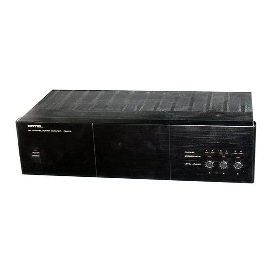
SIX CHANNEL POWER AMPLIFIER
RB-976
®
60 watts/ch into 8 ohms
150 watts/ch into 8 ohms
<0.03%
<0.03%
15 Hz-100 kHz
150
Stereo mode : 4 ohms minimum
Bridged Mono mode : 8 ohms minimum
116 dB
22 k Ohms
1.5 volt
10 mV input signal
5 minutes with no signal
USA : 115 Volts, 60 Hz
Europe : 230 Volts, 50Hz
700 Watts
440 x 121 x 410 mm
17
x 4
x 16
in
3/8
3/4
1/8
12.7kg, 28 lb
Serial. NO.
Beginning
MK @
Y-332A-00115C/S-S
Advertisement
Table of Contents

Related Manuals for Rotel RB-976 MKII


Summary of Contents for Rotel RB-976 MKII
-
Page 1: Table Of Contents
Quality Uncompromised ® T echnical SIX CHANNEL POWER AMPLIFIER RB-976 MK @ Manual Table of Contents Specification........1 Parts List ...........2~3 Adjustment........4 Service Note........4 Case Outlines........5 PCB Assembly ........5~10 Schematic Diagram ......11~12 Specification Continuous Power Output Stereo Mode 60 watts/ch into 8 ohms (20-20 kHz, <0.03%THD) Continuous Power Output Bridged Mono Mode 150 watts/ch into 8 ohms... -
Page 2: Parts List
Parts List-1 SYMBOL PARTS NO. DESCRIPTION SYMBOL PARTS NO. DESCRIPTION X-1280 PCB ASSEMBLY C501.502 041 UTES1H100-FB CAPACITOR ELEC.50V10UF C424 041 UTES1E101-FB CAPACITOR ELEC.25V100UF C503.504 044 S50V330PJ CAPACITOR STYROL 50V330PF D421-423 034 T1N4148-86 DIODE C505.506 044 S50V220PJ CAPACITOR STYROL 50V220PF K401-404 066 4TR-2709#3 2P PINJACK C507.508... - Page 3 Parts List-2 SYMBOL PARTS NO. DESCRIPTION SYMBOL PARTS NO. DESCRIPTION X-1281-04 PCB ASSEMBLY D481-483 034 LTL4262N D902.903 034 T1N4003-TB DIODE D484.485 034 LTL4296N D931.932 034 T1N4003-TB DIODE D486 034 LTL4262N F901.902 036 5ST6.3 ※ MINI FUSE 250VT6.3A D487.488 034 LTL4296N R901 054 TMF3R30 RESISTOR METAL 3.3R...
-
Page 4: Adjustment
Adjustment Instruments : DC milli–meter Notes Prior to Bias Adjustment, run about 5minutes with rated output (8 ohms) And warm up Power Transistor and Heat Sink.Set input off. Step Coupling Location Adjust Adjust for K 3 1 X - 1 2 8 0 -0 1 P CB R 5 3 7 K 3 2 X - 1 2 8 0 -0 1 P CB... -
Page 5: Case Outlines
Case Outline PCB Assembly-1 2SA1943 2SC536K 2SC5200 2SA608K 2SA1016K 2SB631K NJM555D 2SD600K 2SC1941 MPC1237HA... - Page 6 PCB Assembly-2...
- Page 7 PCB Assembly-3...
-
Page 8: Schematic Diagram
Schematic Diagram...
Need help?
Do you have a question about the RB-976 MKII and is the answer not in the manual?
Questions and answers