
Related Manuals for TSI Instruments SidePak AM520


Summary of Contents for TSI Instruments SidePak AM520
- Page 1 SIDEPAK PERSONAL ™ AEROSOL MONITOR MODEL AM520 USER GUIDE P/N 6009829 REV. A JUNE 2016...
- Page 3 90 days from the date of shipment; b. SidePak AM520 internal pump and battery are warranted for one (1) year from the date of manufacture. c. Parts repaired or replaced as a result of repair services are warranted to be free from defects in workmanship and material, under normal use, for 90 days from the date of shipment;...
- Page 4 PROFITS, BUSINESS INTERRUPTION, OR ANY SPECIAL, INDIRECT, CONSEQUENTIAL OR INCIDENTAL DAMAGES. SELLER SHALL NOT BE RESPONSIBLE FOR INSTALLATION, DISMANTLING OR REINSTALLATION COSTS OR CHARGES. No Action, regardless of form, may be brought against Seller more than 12 months after a cause of action has accrued. The goods returned under warranty to Seller's factory shall be at Buyer's risk of loss, and will be returned, if at all, at Seller's risk of loss.
-
Page 5: Table Of Contents
AM520 Displayed Battery Life ............. 10 Installing TrakPro™ Data Analysis Software ......10 CHAPTER 3 OPERATION .............. 11 Overview ..................11 Identifying SidePak AM520 Features .......... 11 USB Port ................11 Power Port ................12 Exhaust Port ................. 12 Inlet ..................12 Battery Screws .............. - Page 6 Information ................26 Calibration ..................26 Zero Cal ................. 28 Flow Cal ................29 User Cal ................30 Data ..................... 31 Statistics ................31 Clear Memory ................ 31 Alarms ..................32 Post-Sampling Data Reporting and Graphing ......34 CHAPTER 4 MAINTENANCE ............35 Returning the Instrument to TSI for Service ........
-
Page 7: Safety Information
Ingress Protection rating, is a set of codes used to define specific levels of protection of the equipment from solids and liquids. IP54 Protected from limited dust ingress Protected from water spray in any direction The SidePak AM520 has an IP Rating of IP54. - Page 8 W A R N I N G / A V E R T I S S E M E N T • THE EFFECT OF THE INTERNAL LASER ON GAS MIXTURES HAS NOT BEEN EVALUATED BY CSA LES EFFETS DU LASER INTERNE SUR LES MELANGES DE GAZ N’ONT PAS ÉTÉ...
- Page 9 W A R N I N G Any damage to the base unit that results in a cracked or broken case should be immediately returned to TSI for repair as it may affect safety rating compliance of the equipment. A damaged case could allow for the ingress of dust, dirt or other material and moisture into the unit and diminish the safety of the device.
- Page 10 (This page intentionally left blank)
-
Page 11: Chapter 1 Unpacking And Parts Identification
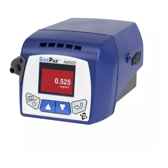
Chapter 1 Unpacking and Parts Identification Carefully unpack the AM520 SidePak™ Personal Aerosol Monitor from the shipping container. Use the table below to identify the components that are included with the unit. A photo and description of each item follows the table. If any parts are missing, contact TSI immediately. - Page 12 Item Description Part/Order Reference Picture Number AM520 Personal AM520 Aerosol Monitor (shown with battery pack) Battery Pack, 5400mAH 803300 Single Carry Case 1319289 11.25” x 9” x 4.25” (28.6 x 22.9 x 10.8 cm) AM520 Impactor Kit 803301 (impactor oil, impactor disc (3x), Blank inlet, inlet, PM inlet,...
- Page 13 Item Description Part/Order Reference Picture Number Calibration Jar, 1ltr 803310 (Accessory sold separately.) (photo courtesy of Zefon) TrakPro™ Data 7003173 Analysis Software CD (Accessory sold separately.) Zero Filter 800663 AM520 Power Supply 803302 with Universal Plug Set AM520 USB Cable 803305 Sample Tube, Tygon®...
- Page 14 Item Description Part/Order Reference Picture Number AM520 Calibration Certificate AM520 User Guide 6009829 Quick Start Guide and 6009830 Keypad Functions SidePak AM520 6009831 Personal Aerosol Monitor Li-Ion Battery Maintenance Card Chapter 1...
-
Page 15: Chapter 2 Setting-Up
Chapter 2 Setting-Up Supplying Power to the SidePak Aerosol Monitor Attach the rechargeable battery pack to the SidePak™ Personal Aerosol Monitor before use. This will “wake up” the battery from storage mode. The battery can power the AM520 by itself or in conjunction with the TSI AC adapter. -
Page 16: Installing The Lithium Ion Battery Pack
Installing the Lithium Ion Battery Pack 1. Place the battery pack under the AM520. 2. Push firmly to slide into place. 3. Fasten it in place using the two battery screws provided. Chapter 2... -
Page 17: Removing The Lithium Ion Battery Pack
Removing the Lithium Ion Battery Pack 1. To remove battery, remove battery screws. 2. Firmly grip sides of instrument and sides of battery. 3. Pull apart. AM520 Smart Battery Management System™ technology The rechargeable Lithium Ion battery pack is designed with Smart Battery Management System™... -
Page 18: Storing The Battery Pack Between Uses
The SBMS supervisor prevents the battery from overcharging when the AC adapter has been left plugged into the battery. At end of the charge cycle the SBMS supervisor disconnects (stops charging) the cells while continuing to pass power on to the instrument. The SBMS supervisor also prevents excessive discharge when the battery is depleted. -
Page 19: Using The Ac Adapter (Power Supply)
W A R N I N G / A V E R T I S S E M E N T Remove LiOn battery during storage and transportation of instrument. Using the AC Adapter (power supply) The AC adapter powers the AM520 from an AC wall outlet, and charges the rechargeable battery... -
Page 20: Battery Led
If the AC adapter is plugged in, "A/C Power" is displayed. Installing TrakPro™ Data Analysis Software TrakPro Data Analysis Software can preprogram the SidePak AM520 monitor, download data, view data, create graphs and statistical reports, and combine graphs with data from other TSI instruments that use TrakPro software. -
Page 21: Chapter 3 Operation
USB (Universal Serial Bus) communications cable. Identifying SidePak AM520 Features USB Port Use the Universal Serial Bus (USB) port and USB cable to connect the SidePak AM520 to an available USB port on your computer. The connector on the instrument is a USB Micro-B receptacle. -
Page 22: Power Port
Power Port Connect the power supply to this port to charge the TSI battery pack or to power the instrument at any time. Note Many power supplies look alike. Use the proper power supply to prevent damage. Note After charging the battery, close/seal the AC power port with the attached AC dust plug. -
Page 23: Battery Screws
Battery Screws Remove these two screws to remove the battery. W A R N I N G / A V E R T I S S E M E N T BATTERY TO BE CHARGED ONLY WITH POWER SUPPLY 6001583. BATTERIE A CHERGER UNIQUEMENT AVEC L’ALIMENTATION 6001583. -
Page 24: Keypad Functions
Keypad Functions To turn the instrument ON, press the ESC key. To turn the instrument OFF, press and hold the ESC key for three (3) seconds (release key when the countdown reaches "0 SECONDS." The model number, serial number, and firmware revision are displayed for a few seconds before entering Survey Mode. -
Page 25: Main Menu
Main Menu The menu structure of the SidePak monitor is very easy to use. The graphic below shows the menu structure from the Main Menu. After power up, the instrument will be in Survey Mode as indicated by the From the Main Menu, use the ▲ ▼ keys to select one of the following category menus and then press the Enter key: •... -
Page 26: Power Up
Power Up Turn the SidePak AM520 on by pressing the ESC key. The instrument displays the TSI logo followed by the model number, serial number, and firmware version. The instrument will begin Survey Mode. "Survey" will display briefly, then just the survey mass concentration reading. -
Page 27: Data Logging
In this mode, the pushbuttons can be locked by first pressing key, then simultaneously pressing ENTER key. A red lock icon briefly shown to indicate that the keys are locked. The keys can be unlocked in the same fashion: by first pressing the key, then simultaneously pressing ENTER key. - Page 28 The “PROG DELAY” screen will disappear after a few seconds and “PROG DELAY” will flash briefly once every two seconds to show that the AM520 is waiting to start. If a key is pressed while the AM520 is waiting, it will show the full “PROG DELAY”...
-
Page 29: Run Mode
To stop logging or cancel a logging program, press the ESC key. If logging is already in process, you will have to confirm by pressing ENTER. When data logging stops, the AM520 displays a message showing whether any data was saved. Run Mode The Run Mode menu contains the following options:... -
Page 30: Settings
During data logging, use the ESC key to view: • • Battery life remaining Current time and date displayed in minutes • Log interval • 8-hour TWA • Elapsed time If the user-selectable screen save delay elapses without a key being pressed, the display reverts back to the LOGGING DATA screen saver. -
Page 31: Setting The Log Interval
Intervals can be used to conserve memory for long duration tests. The SidePak AM520 always makes a measurement once every second regardless of the log interval selected. Using a log interval greater than one second results in stored data points that are averages of the 1-second readings. -
Page 32: Setting The Time Constant
Constant only affects the AM520 display. Log intervals only affect recorded readings. The SidePak AM520 always makes a measurement once every second and updates the display every second regardless of the Time Constant selected. Using a Time Constant greater than one second results in displayed readings that are averages of the 1-second readings. - Page 33 Log Interval vs. Time Constant • The Log Interval is the time interval used between recorded data points. It can be set using the SETTINGS menu and in Program logging mode using TrakPro software. • The AM520 always takes a measurement once every second regardless of the Log Interval.
-
Page 34: Setting The Time And Date And Date Format
Setting the Time and Date and Date Format Set the Date Format The date format is user-selectable. The formats available are: • yyyy/mm/dd (default) • mm/dd/yyyy • dd/mm/yyyy where yyyy is the 4-digit year, mm is the 2-digit month, and dd is the 2-digit day of month. -
Page 35: Battery Units
Set the Current Date 1. Select SETTINGS from the MAIN MENU with the ▲ ▼ keys and press ↵. 2. Under SETTINGS menu, select TIME/DATE with the ▲ ▼ keys and press ↵. 3. Under TIME/DATE menu, select the date and press RETURN. 4. -
Page 36: Language
Language The display language can be changed to English (default) or Chinese. To set the language: 1. Select SETTINGS from the MAIN MENU with the ▲ ▼ keys and press ↵. 2. Under SETTINGS menu, select Language with the ▲ ▼ keys and press ↵. - Page 37 Effect of Calibration Factors on Full Scale and Alarms • Note that the AM520 maximum full scale reading is not fixed at 100 mg/m³; it changes when the Calibration Factor is changed. • For instance, if a Calibration factor of 2.00 is chosen, all readings are multiplied by 2.00, and the effective maximum full scale reading of the AM520 is then 200 mg/m³.
-
Page 38: Zero Cal
Zero Cal For best results, it is important to zero the AM520 before each test. This ensures accurate data, especially for low aerosol concentrations. The process only takes a few minutes. 1. Locate the zero filter provided with the AM520 kit and attach it to the inlet of the SidePak monitor. -
Page 39: Flow Cal
Flow Cal Aerosol concentration measurements with the SidePak AM520 are accurate regardless of the flow rate through the instrument. However, size-selective aerosol sampling inlets such as impactors and cyclones require specific flow rates to function within their design specifications. If using a size-selective inlet, adjust the flow rate precisely. -
Page 40: User Cal
User Cal Selecting a Photometric Calibration Factor will cause the SidePak monitor's response for all subsequent measurements to be multiplied by the new calibration factor. User cal 1 to 7 can be selected through the user interface or TrakPro software. To select the calibration factor through the user interface: 1. -
Page 41: Data
4. The Statistics menu displays computed statistics for each test (up to 100 tests) that have been made using Run Manual, and Prog 1 through Prog 7 data logging methods. The statistics computed by the SidePak AM520 include: • Max: Maximum concentration value recorded (mg/m •... -
Page 42: Alarms
To Clear Memory 1. Select Data from the MAIN MENU with the ▲ ▼ keys and press ↵. 2. Under DATA menu, select Clear Memory with the ▲ ▼ keys and press ↵. 3. You will be prompted to confirm your intention. 4. - Page 43 STEL Record length is selectable from 5 to 30 minutes through TrakPro™ software. Since the start of a STEL Record is not usually aligned with the Log Interval, the values of averages saved in the STEL Record will generally not match the values saved each Log Interval.
-
Page 44: Post-Sampling Data Reporting And Graphing
See the product information of the TSI TrakPro v5 software for all the features and capabilities that enhance the use of your SidePak AM520 Personal Aerosol Monitor. TrakPro v5 software is available for download from the TSI website at: http://www.tsi.com/Software-Firmware/. -
Page 45: Chapter 4 Maintenance
• Zeroing In addition to the procedures in this chapter, TSI recommends that you return your SidePak AM520 Personal Aerosol Monitor to the factory for annual calibration. Regular factory-authorized cleaning and recalibration helps ensure that your instrument is working properly, has the latest updates, and will provide accurate and reliable measurements. -
Page 46: General Cleaning
General Cleaning General cleaning of the SidePak AM520 case should be done with soap and water applied with a damp cloth. Do not use chemical cleaners, alcohol or petroleum derived cleaners on the case or front panel of the instrument. - Page 47 SidePak size-selective inlets use an internal impactor disk. The impactor disk functions as a collection plate where particles larger than the cut-size are trapped. The same impactor disk is used for all impactors, but it is not used for the standard inlet. To make sure unwanted (large) particles remain trapped on the impactor disk, it is necessary to apply 1 to 4 drops of impactor oil on the impactor disk...
- Page 48 Clean the impactor inlet and impactor disk with a clean lint-free swab or microfiber cloth and light solvent. Gently blow impactor body dry with canned/pressurized clean air or allow to air dry. Use a lint-free swab or microfiber cloth to clean impactor well inside the instrument case to remove accumulated particles.
-
Page 49: Using And Maintaining The Respirable Cyclone
Particles larger than 4 µm impact onto the surfaces of the upper respiratory tract and cannot reach the lungs. The cyclone accessory provided with SidePak AM520 is designed to provide a cut- off at 4 µm. This is specified as a 50% cut-off at 4 µm. -
Page 50: Cleaning The Cyclone
AM520 monitor be set at 1.7 liters per minute (L/min). If some other flow rate is set, the cut-off size will be unknown. 1. Install the standard inlet (unmarked) on the SidePak AM520 body without an impactor disk inside. 2. Attach the cyclone and sample tube onto the AM520 inlet. -
Page 51: Using And Maintaining The Diesel Particulate Matter Dpm Cyclone
3. Re-assemble the cyclone. Note that the stainless steel cyclone clip that holds the cap onto the body will only fit one way. The cyclone cleaning procedure is now completed. Exploded View of 10 mm Nylon Dorr-Oliver Cyclone Using and Maintaining the Diesel Particulate Matter DPM Cyclone The DPM Cyclone included with the AM520 can be used to differentiate between the diesel particulate matter and other portions... - Page 52 1.7 liters per minute (L/min). If some other flow rate is set, the cut-off size will be unknown. 1. Be sure to have the standard inlet (unmarked) installed on the SidePak AM520 body and that there is no impactor disk inside. 2. Attach the Dorr-Oliver cyclone to the DPM cyclone to create the DPM assembly.
-
Page 53: Cleaning The Diesel Particulate Matter Dpm Cyclone
4. Adjust the flow rate of the AM520 to 1.7 L/min. See Chapter 3, “Operation” for instructions on how to set the flow rate. TSI 4146 flow meter (sold separately) being used to calibrate flow setting for AM520 The SidePak monitor and DPM cyclone assembly are now ready to use. - Page 54 3. Re-assemble the cyclone. Note that the stainless steel cyclone clip that holds the cap onto the body will only fit one way. The cyclone cleaning procedure is now completed. Exploded View of 0.8 µm DPM Cyclone Note When re-assembling the cyclone, fully seat the cap to maintain the proper flow rate.
-
Page 55: Calibrating Of Measuring Dpm
(as shown) Example Calibration Setup AM520 Field Service Kit – sold separately The SidePak AM520 Field Service Kit (P/N 803306) includes the following to replace damaged or lost items: Description USB Dust Plugs Impactor Plates... - Page 56 (This page intentionally left blank) Chapter 4...
-
Page 57: Chapter 5 Troubleshooting
If you are having a problem with your SidePak AM520, use the information below to try and resolve it in the field. If necessary, contact TSI Incorporated or a local TSI distributor to arrange for service. -
Page 58: Troubleshooting Table
Troubleshooting Table Symptom Possible Cause Corrective Action Erratic zero reading. Leak. Check all connections for leaks. Carefully tighten sample inlet screws (do not over- tighten!). If using an impactor, remove, clean and re-oil the impactor disc. Make sure the O-ring is in place and not damaged. - Page 59 Symptom Possible Cause Corrective Action No keypad response. Keypad is locked To unlock the keypad, press and hold the ▲ key Display shows a red out. When the and press ↵. lock icon. keypad is locked, the display shows a Data Logging red lock icon.
- Page 60 Symptom Possible Cause Corrective Action LOG PROGRAM There is a problem Use TrakPro software to READ with an entered read and set the logging logging program. programs. If error recurs, return to factory for LOG PROGRAM servicing. WRITE error message is displayed.
- Page 61 Symptom Possible Cause Corrective Action COIN CELL VOLTAGE The coin cell used to Download logged data to power the clock and TrakPro software (if desired error message is store logged data is to save). Return to factory displayed. depleted. for servicing. METER ID READ There is a problem Return to factory for...
-
Page 62: Technical Contacts
TSI Customer Service at 1-800-874- 2811 (USA) or (651) 490-2811. International Contacts Service TSI Instruments Singapore Pte Ltd 150 Kampong Ampat #05-05 KA Centre Singapore 368324 Telephone:... -
Page 63: Technical Support
HP12 3ST UNITED KINGDOM Telephone: +44 (0) 149 4 459200 Fax: +44 (0) 149 4 459700 E-mail: tsiuk@tsi.com Technical Support TSI Instruments Singapore Pte Ltd 150 Kampong Ampat #05-05 KA Centre Singapore 368324 Telephone: +65 6595-6388 Fax: +65 6595-6399 E-mail: tsi-singapore@tsi.com... - Page 64 Neuköllner Strasse 4 52068 Aachen GERMANY Telephone: +49 241-52303-0 Fax: +49 241-52303-49 E-mail: tsigmbh@tsi.com TSI Instruments Ltd. Stirling Road Cressex Business Park High Wycombe, Bucks HP12 3ST UNITED KINGDOM Telephone: +44 (0) 149 4 459200 Fax: +44 (0) 149 4 459700 E-mail: tsiuk@tsi.com...
-
Page 65: Returning For Service
Returning for Service Visit our website at http://rma.tsi.com and complete the on-line “Return Merchandise Authorization” form or call TSI at 1-800-874- 2811 (USA), (651) 490-2811, or 001 651 490-2811 (International) for specific return instructions. Customer Service will need the following information: •... - Page 66 (This page intentionally left blank) Chapter 5...
-
Page 67: Appendix A Specifications
Appendix A Specifications Specifications are subject to change without notice. Sensitivity Sensor type 90° light scattering, 650 nm laser diode Aerosol concentration 0.001 to 100 mg/m (calibrated to range respirable fraction of ISO 12103-1, A1 Test Dust) Particle size range 0.1 to 10 µm Minimum resolution 0.001 mg/m... - Page 68 Built-in Inlets Standard inlet Not size-specific impactor 50% cut-off at 1.0 µm impactor 50% cut-off at 2.5 µm impactor 50% cut-off at 5.0 µm impactor 50% cut-off at 10.0 µm Attachable Cyclones 4 µm Dorr-Oliver 50% cutoff at 4.0 µm 0.8 µm DPM 50% cut-off at 0.8 µm Alarms...
- Page 69 Physical External dimensions 5.1 x 3.7 x 3.1 inch (129.5 x 94 x 78.4 mm) with 803300 battery Weight 22 oz (0.62 kg) with 803300 battery Display 160 x 128 resolution color OLED display Tripod socket ¼-20 female thread Battery Rating 5400 mAH Li-Ion Pack Run Time...
- Page 70 Approvals AM520 with TSI Battery Pack P/N 803300 0344 Immunity EN61326-1:2013 Emissions EN61326-1:2013 Class B IEC 61010-1:2010 Safety IEC 60825-1:2014 Appendix A...
-
Page 71: Appendix B Custom Calibrations
Appendix B Custom Calibrations In most situations, the Model AM520 provides very good information on how the concentration of an aerosol changes for over time. Factory calibration to the respirable fraction of standard ISO 12103-1, A1 Test Dust (aka, Arizona Test Dust) allows comparisons between measurements where the source or type of dust is predominately the same. -
Page 72: Developing A Photometric Calibration Factor For A Specific Aerosol
Developing a Photometric Calibration Factor for a Specific Aerosol The SidePak AM520 Personal Aerosol Monitor is factory calibrated to the respirable fraction of standard ISO 12103-1, A1 Test Dust. The SidePak AM520 monitor can be easily calibrated to any arbitrary aerosol by adjusting the photometric calibration factor. - Page 73 5. Start photometer and sampling pump at same time, sample for same duration. • Data log aerosol measurements with photometer. • Collect gravimetric sample with sample pump. • Sample time does not need to be full shift like compliance monitoring. The key is to collect at least the minimum volume necessary for valid analysis with the analytical method.
- Page 74 12. Compare gravimetric and PCF photometric sample data. • Results should be closer, “more accurate,” using the new PCF. Note Greater accuracy will be obtained with longer samples. The time you permit for sampling often depends on the reference instrument and characteristics of the measured aerosol.
-
Page 75: Appendix C Converting Stored Data To Calibrated Data
Appendix C Converting Stored Data to Calibrated Data A single set of logged data can be converted to data calibrated to a specific aerosol with the use of the TrakPro™ Data Analysis Software. This conversion can be done by knowing either the true mass concentration for the logged data or the calibration factor for the aerosol. - Page 76 (This page intentionally left blank) Appendix C...
- Page 77 TSI Incorporated – Visit our website www.tsi.com for more information. Tel: +1 800 874 2811 India Tel: +91 80 67877200 Tel: +44 149 4 459200 China Tel: +86 10 8219 7688 France Tel: +33 1 41 19 21 99 Singapore Tel: +65 6595 6388 Germany Tel: +49 241 523030 P/N 6009829 Rev A ©2016 TSI Incorporated...
Need help?
Do you have a question about the SidePak AM520 and is the answer not in the manual?
Questions and answers