
Related Manuals for Federal Signal Corporation Rumbler 2


Summary of Contents for Federal Signal Corporation Rumbler 2
-
Page 1: Operation Instructions
Model Rumbler ® Low Frequency Siren Amplifier Installation and Operation Instructions 2562420B REV. B2 0714 Printed in U.S.A. - Page 2 blank page...
-
Page 3: Table Of Contents
Contents Introduction ............................1 Features ..............................1 Applications ..............................1 Safety Message to Installers of Federal Signal Light and Sound Systems ........2 Unpacking and Inspecting the R 2 ..................3 umbleR Mounting the R 2 in the Vehicle ....................3 umbleR Wiring the R 2 in the Vehicle ....................5 umbleR Connecting a Speaker ..........................5 Connecting the Input Leads ........................5... - Page 4 Contents...
-
Page 5: Introduction
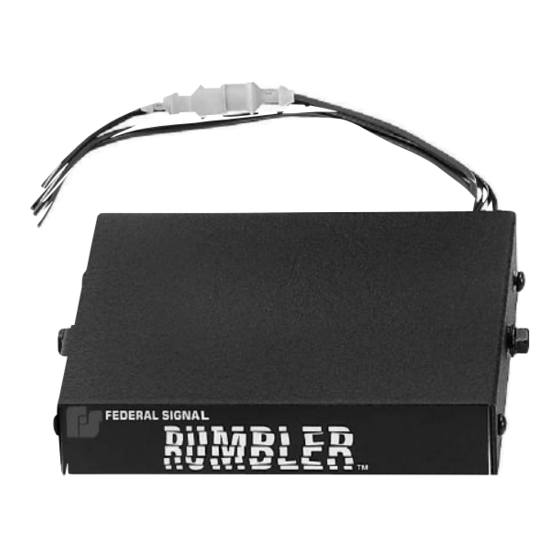
Introduction The Federal Signal R 2 Low Frequency Siren Amplifier incorporates the latest solid-state designs ® umbleR for superior reliability and sound quality. The R 2 uses the output of a standard emergency vehicle umbleR siren and synthesizes a low frequency signal. It then amplifies that signal to drive a Federal Signal Low Frequency Siren Speaker. -
Page 6: Safety Message To Installers Of Federal Signal Light And Sound Systems
Safety Message to Installers of Federal Signal Light and Sound Systems Safety Message to Installers of Federal Signal Light and Sound Systems The lives of people depend on your safe installation of Federal Signal products. It is important to read and follow all instructions shipped with the products. In addition, listed below are some other important safety instructions and precautions you should follow. -
Page 7: Unpacking And Inspecting The R Umbler 2
10-32 hex nuts. An additional installer-supplied 15 A fuse and in-line fuse holder are also required for fusing the Rumbler 2 at the power source. The amplifier is activated through the horn ring circuit or an installer-supplied momentary switch. -
Page 8: Mounting The Rumbler 2 In The Vehicle
Mounting the Rumbler 2 in the Vehicle UNIT REQUIRES VENTILATION The R 2 needs to radiate heat. Do not install it in an area where it cannot dissipate heat into umbleR the air. Do not mount it near a heater duct or under the vehicle’s hood. -
Page 9: Wiring The Rumbler 2 In The Vehicle
Wiring the Rumbler 2 in the Vehicle Wiring the R 2 in the Vehicle umbleR FIRE HAZARD If shorted to the vehicle frame, high current conductors can cause hazardous sparks resulting in electrical fires or molten metal. DO NOT connect this system to vehicle battery until ALL other electrical connections are made and mounting of all components is complete. -
Page 10: Connecting The Activation Input
BATTERY DRAIN The Rumbler 2 system does not have an on-off switch. If power for the Rumbler 2 is obtained directly from the vehicle battery, it draws approximately 0.20 Ah per day in standby mode. If you are connecting the Rumbler 2 to the switched side of the ignition circuit, make sure the circuit has enough current capacity to handle the additional 10 A (approx.) load. -
Page 11: Setting The 8-60 Second Timer
For more information on sound exposure, refer to the warnings in “Safety Messages to Operators of Federal Signal Light and Sound Systems” on page 9 and in “Operating the Rumbler 2” on page 10. -
Page 12: Testing The Rumbler 2 After Installation
Testing the Rumbler 2 After Installation Failure to follow this warning may result in hearing damage to operators and passengers. To set the timer: Remove the R 2 from the mounting brackets. umbleR Locate the slot on the left side of the top cover. -
Page 13: Safety Message To Operators Of Federal Signal Light And Sound Systems
Safety Message to Operators of Federal Signal Light and Sound Systems After testing is complete, provide a copy of this manual to all operating personnel. Safety Message to Operators of Federal Signal Light and Sound Systems The lives of people depend on your safe operation of Federal Signal products. It is important to read and follow all instructions shipped with the products. -
Page 14: Operating The R Umbler 2
10 Operating the Rumbler 2 Failure to follow these safety precautions may result in property damage, serious injury, or death. Operating the R umbleR The R 2 has no user switches on the amplifier unit. Refer to your standard siren system manual for umbleR instructions on using your system. -
Page 15: Getting Parts And Service For The R Umbler 2
Getting Parts and Service for the Rumbler 2 jury, or death. Getting Parts and Service for the R umbleR The factory can and will service your equipment or assist you with technical problems that cannot be handled satisfactorily and promptly locally. - Page 16 2645 Federal Signal Drive, University Park, IL 60484-3167 Tel.: (800) 264-3578 • Fax: (800) 682-8022 www.fedsig.com © 2012 Federal Signal Corporation...
Need help?
Do you have a question about the Rumbler 2 and is the answer not in the manual?
Questions and answers